TIS MS-PIR-M User manual

The Tis Bus PIR is a sensor with functional usage
in areas where motion detection is a priority. It
can also be programmed to use the least amount
of energy possible. It has a lux meter, which
determines the lux amount and helps customize
lights.
PRODUCT INFORMATION
6 58921 79722 8
BARCODE (UPC-A)
PRODUCT SPECIFICATIONS
PIR, Lux and Dry inputs
PIR motion sensor Dual element pyro-electric ceramic
Digital input. Open / Close 2 Channels
Length of connected wire to DI < 350 meter
Light intensity sensor 0 – 8000 Lux meter
Temperature sensor
accuracy +/- 0.3 C
Operating Range -40°C – 85°C
Respond Time 5-30 Seconds
TIS Bus
Number of devices on 1 line Max. 64
Bus voltage 12-32 V DC
Current consumption <15 mA / 24 V DC
PIR Detection PIR range 4-6 meters (installation height 2.6 - 3 meters)
PIR detection angle 110° from the celling down
Operating and display elements
Programming button For assignment of the physical address
Indicator LED Blue or Red LED (optional)
TIS bus TIS Protocol maessages and commands
Functions
Logic/ Timers 32 Timers and Logic conditions
IR Code memory / Flags 250 IR code memory & flags
Security Function Away, Night, Day, fire alarm setting
IR receiver 8 buttons function
Weight Without packaging 0.06 KG
Dimensions Width ×length × height 92mm ×39 mm ×92mm
Housing
Materials ABS anti fire / PC anti fire
Casing color Gray White
Base color Black
IR window cover Transparent White
IP rating IP 20
Temperature range
Operation -10…60°C
Storage -20…50°C
Transport -25…75°C
Air humidity <85% non-condensing
TIS CELLING MOUNT MOTION SENSOR
INSTALLATION MANUAL
Model: MS-PIR-CM

2
INSTALLATION MANUAL
Model: MS-PIR-CM
TIS CONTROL LIMITED
RM 1502-p9 Easey CommBldg
253-261 Hennessy Rd Wanchai
Hong Kong
TEXAS INTELLIGENT SYSTEM LLC
SUITE# 610. 860 NORTH DOROTHY DR
RICHARDSON
TX 75081.USA
Copyright © 2020 TIS, All Rights Reserved
TIS Logo is a Registered Trademark of Texas Intelligent System LLC in the
United States of America. This company takes TIS Control Ltd. in other
countries. All of the Specifications are subject to change without notice.
www.tiscontrol.com
TIS CELLING MOUNT MOTION SENSOR
Mounting Location
Install in a dry, indoor area with a suitable
temperature and humidity range.
Data Cable
Use screened stranded RS485 data cable
with four twisted pairs. Congure devices in
a “Daisy Chain.”
Do not cut or terminate live data cables.
Warranty
There is a two-year warranty provided
by law. The hologram warranty seal and
product serial number are available on
each device.
Read Instructions
We recommend that you read this
Instruction Manual before installation.
Safety instructions
Electrical equipment should only be
installed and tted by electrically skilled
persons.
Failure to follow the instructions may cause
damage to the device and other hazards.
These instructions are an integral part of
the product and must remain with the end
customer.
Programming
Advanced programming requires
knowledge of the TIS Device Search
software and instruction in the TIS
advanced training courses.
Simple Installation
You can use 2 screws to install this sensor
on the celling.
3
INSTALLATION MANUAL
Model: MS-PIR-CM
TIS CONTROL LIMITED
RM 1502-p9 Easey CommBldg
253-261 Hennessy Rd Wanchai
Hong Kong
TEXAS INTELLIGENT SYSTEM LLC
SUITE# 610. 860 NORTH DOROTHY DR
RICHARDSON
TX 75081.USA
Copyright © 2020 TIS, All Rights Reserved
TIS Logo is a Registered Trademark of Texas Intelligent System LLC in the
United States of America. This company takes TIS Control Ltd. in other
countries. All of the Specifications are subject to change without notice.
www.tiscontrol.com
TIS CELLING MOUNT MOTION SENSOR
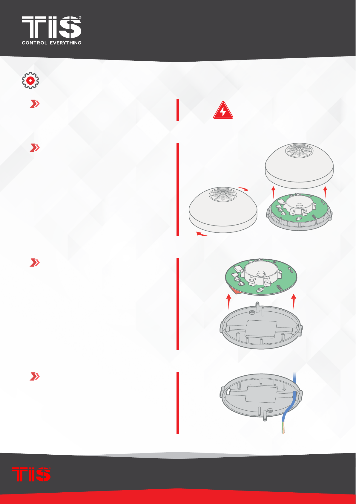
INSTALLATION STEPS
2Rotate the sensor cover to open it
3remove the PCB from the holding pins
4open the wire hples and insert the TIS-
bus cable and other dry inputs cable to
the sensor base.
1Turn off TIS power supply.
WARNING! HIGH VOLTAGE
4
INSTALLATION MANUAL
Model: MS-PIR-CM
TIS CONTROL LIMITED
RM 1502-p9 Easey CommBldg
253-261 Hennessy Rd Wanchai
Hong Kong
TEXAS INTELLIGENT SYSTEM LLC
SUITE# 610. 860 NORTH DOROTHY DR
RICHARDSON
TX 75081.USA
Copyright © 2020 TIS, All Rights Reserved
TIS Logo is a Registered Trademark of Texas Intelligent System LLC in the
United States of America. This company takes TIS Control Ltd. in other
countries. All of the Specifications are subject to change without notice.
www.tiscontrol.com
TIS CELLING MOUNT MOTION SENSOR
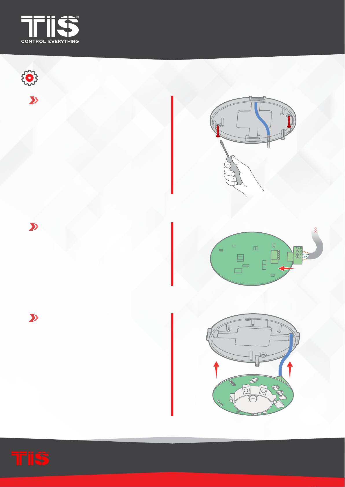
INSTALLATION STEPS
5Mount the sensor base on the celling by
2 screws.
6connect the cables to the the 4 pins
terminals
To the TIS BUS Network
Cat5e
7insert the terminal to the pcb and nstall
the PCB to the sensor base pins

5
INSTALLATION MANUAL
Model: MS-PIR-CM
TIS CONTROL LIMITED
RM 1502-p9 Easey CommBldg
253-261 Hennessy Rd Wanchai
Hong Kong
TEXAS INTELLIGENT SYSTEM LLC
SUITE# 610. 860 NORTH DOROTHY DR
RICHARDSON
TX 75081.USA
Copyright © 2020 TIS, All Rights Reserved
TIS Logo is a Registered Trademark of Texas Intelligent System LLC in the
United States of America. This company takes TIS Control Ltd. in other
countries. All of the Specifications are subject to change without notice.
www.tiscontrol.com
TIS CELLING MOUNT MOTION SENSOR
INSTALLATION STEPS
8
9
10
install the extra 3 screws (optional)
close the cover of the sensor.
Turn the power supply ON. The sensor
LED should turn on.
6
INSTALLATION MANUAL
Model: MS-PIR-CM
TIS CONTROL LIMITED
RM 1502-p9 Easey CommBldg
253-261 Hennessy Rd Wanchai
Hong Kong
TEXAS INTELLIGENT SYSTEM LLC
SUITE# 610. 860 NORTH DOROTHY DR
RICHARDSON
TX 75081.USA
Copyright © 2020 TIS, All Rights Reserved
TIS Logo is a Registered Trademark of Texas Intelligent System LLC in the
United States of America. This company takes TIS Control Ltd. in other
countries. All of the Specifications are subject to change without notice.
www.tiscontrol.com
TIS CELLING MOUNT MOTION SENSOR
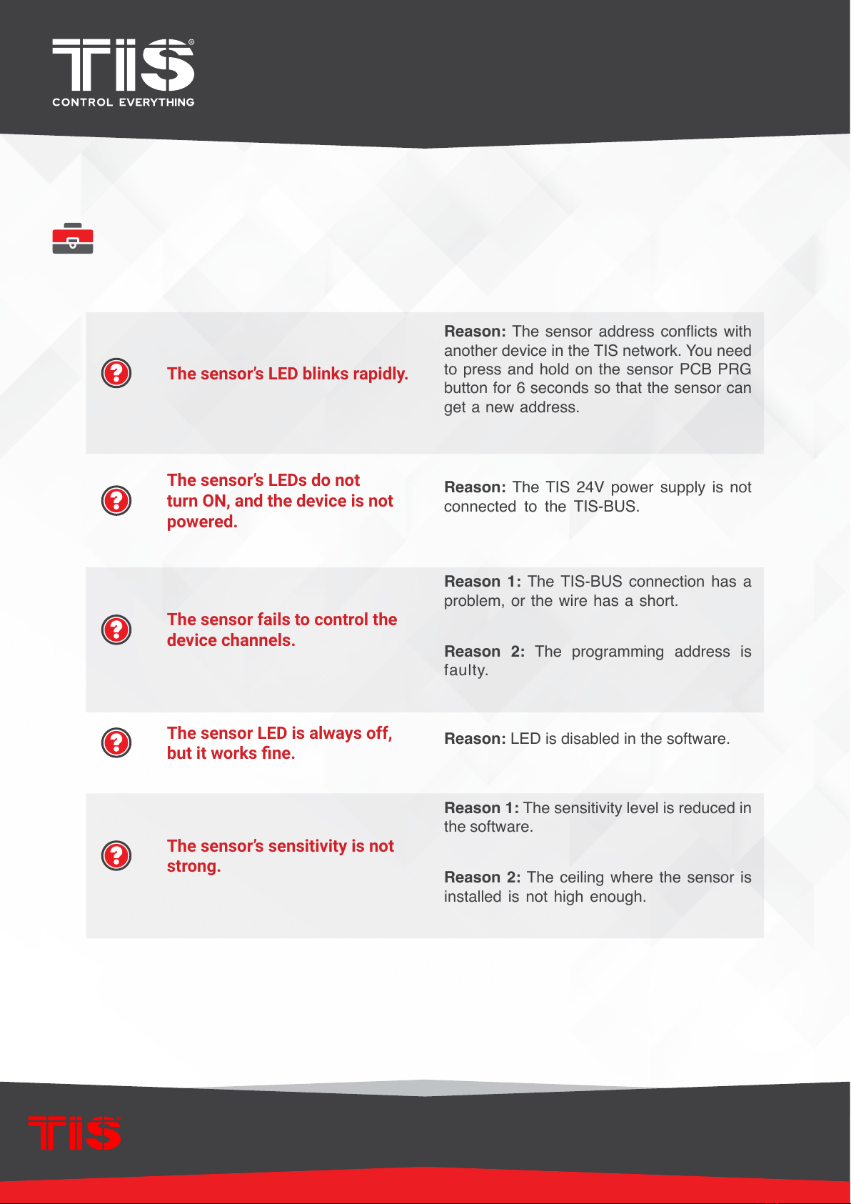
TROUBLESHOOTING
The sensor’s LED blinks rapidly.
Reason: The sensor address conicts with
another device in the TIS network. You need
to press and hold on the sensor PCB PRG
button for 6 seconds so that the sensor can
get a new address.
The sensor’s LEDs do not
turn ON, and the device is not
powered.
Reason: The TIS 24V power supply is not
connected to the TIS-BUS.
The sensor fails to control the
device channels.
Reason 1: The TIS-BUS connection has a
problem, or the wire has a short.
Reason 2: The programming address is
faulty.
The sensor LED is always off,
but it works ne. Reason: LED is disabled in the software.
The sensor’s sensitivity is not
strong.
Reason 1: The sensitivity level is reduced in
the software.
Reason 2: The ceiling where the sensor is
installed is not high enough.
Table of contents
Other TIS Accessories manuals


Popular Accessories manuals by other brands


Redline Communications
Redline Communications RedMAX AN100U Administration and maintenance guide

Siemens
Siemens IR270CT user manual

Bang & Olufsen
Bang & Olufsen BEOLINE Guides & online training

PCB Piezotronics
PCB Piezotronics Y482B06 Installation and operating manual

Spice
Spice SPP030 user manual

Amphenol
Amphenol Temposonics E-Series Operation manual