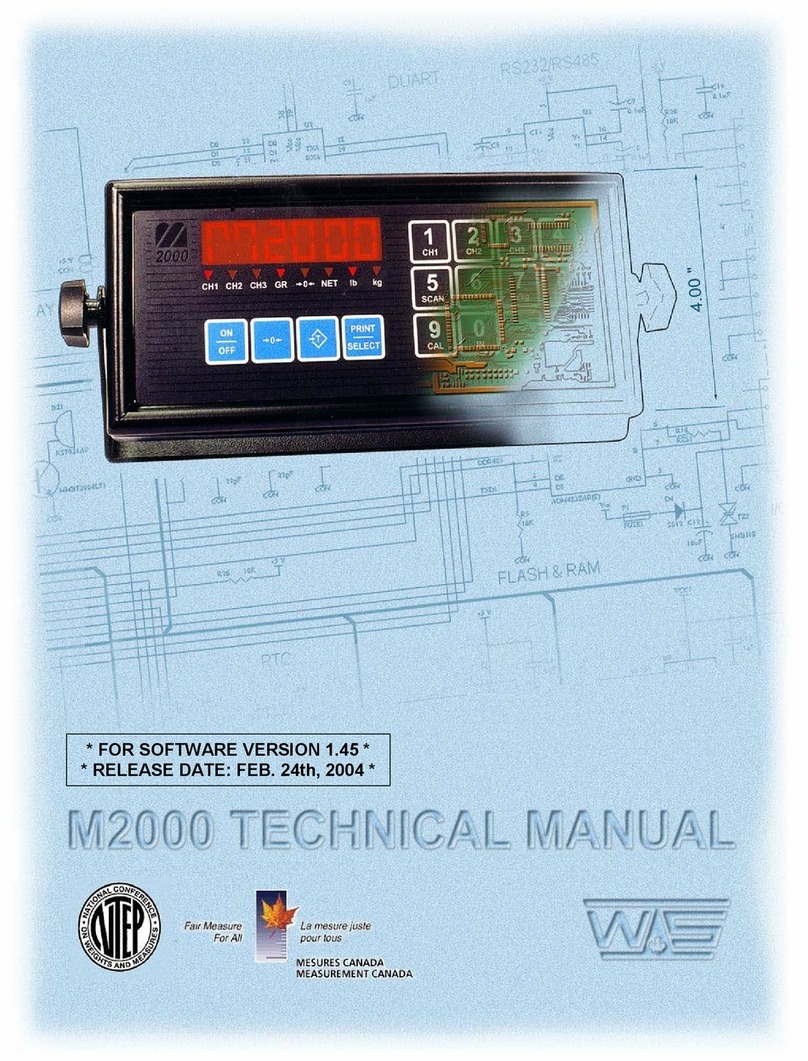
Emery Winslow 7600E Quick guide

1
Configuration and Setup
V4.31
Model 7600E
Digital Weight Display

2
TABLE OF CONTENTS
SPECIFICATIONS....................................................4
DIMENSIONS……………………………………………5
INSTALLATION.........................................................6
SETUP ACCESS ......................................................7
MENU LAYOUT........................................................8
CONFIGURATION....................................................9
CALIBRATION........................................................11
REMOTE SERIAL DISPLAY...................................12
SERIAL PORTS ....................................................14
SERIAL COMMANDS.............................................15
ANALOG OUTPUT .................................................17
DIGITAL INPUT/OUTPUT.......................................18
SETPOINTS, BATCHING .......................................19
SERIAL COMMUNICATION (Setpoint/Accumulator).38
TIME & DATE..........................................................39
WEIGH IN/OUT.......................................................40
TEN POINT LINEARIZATION ……………………..43
TOTALIZER (Accumulator) ……………………….…43
SMART SERIAL......................................................44
DISPLAY MESSAGES............................................52
115/220 VAC...........................................................53
SPARE PARTS.......................................................54
DIGITAL CONFIGURATION RECORD...................55

3
Alternate Packaging for
extreme wash-down and with
Totalizer in common enclosure
Emery Winslow Scale Company
73 Cogwheel Lane 4530 North 25th Street
Seymour, CT 06483 Terre Haute, IN 47805
(203) 881-9333 (812) 466-5265
(203) 881-9477 FAX (812) 466-1046 FAX

4
SPECIFICATIONS
LOAD CELL A/D CONVERTER
TYPE: 24 bit delta sigma (1:16,777,216)
EXCITATION: 5 VDC, 120 mA max.
SIGNAL INPUT: 16 mv
SENSITIVITY: 0.1 uV/grad
UPDATE RATE: 30 update/second
DISPLAY: Six (6) Decades, 0.6 inch LED
KEYPAD: Full numeric plus controls
POWER INPUT: 117/217 VAC, 50‑60 HZ, 20 watts, fuse 0.50 A Slo-Blow.
SERIAL PORTS:
Port 1: RS232C or 20ma
Port 2: RS485, RS232C or 20mA.
Smart Serial Setup: 8 custom print files plus 8 macro files, 30 characters each.
Batch Start/Stop: Control from front panel or remote input.
Setpoint Operation: 4 output relays configurable for normal setpoints,
over/under or manual/auto batch modes.
TIME & DATE: 12/24 hr, battery backed.
ENCLOSURE: Stainless Steel, NEMA 4X, Tilt-Stand Base, 7lbs.
CASE: 8.82” (w) x 6.31” (h) x 4” (d) Tilt or panel mount.
NRTL: Met Labs file E112367 certified to UL60950-1, CAN/CSA-C22.2 60950-1-03
NTEP: Class III/IIIL, 10,000 divisions CoC 97-009A4
OPTIONS:
ANALOG OUTPUT: 0-10v, 4-20ma (16 bit D/A).
DIO: 4 AC/DC –inputs, 4 AC/DC outputs (SS Relays, 0.5 amp)
ETHERNET TCP/IP
DUAL CHANNEL

5
DIMENSIONS

6
CalSwitch SW-4
TB-1
———-1——–Signal +
———-2——–Signal -
———-3-——Sense -
———-4—— Excitation -
———-5——-Sense +
——-—6——-Excitation +
SenseJumpers
Option Header
Analog Output
A/DRFIShield
Software Version#
VX.XX
INSTALLATION
POWER WIRING: The indicator is designed to be operated from 117/217 VAC,
50‑60 Hz. The unit power cord must be plugged into a grounded 3 ‑wire polarized
AC wall socket. All normal wiring and grounding precautions should be observed,
including use of a "clean" AC power line.
SCALE WIRING: The unit is equipped with cable gland entry for load cell cable
insertion and internal (pluggable) terminal strip for 4 / 6 wire connection.
Remove sense jumpers P11-8/7, P11-6/5 for six wire.

7
SETUP ACCESS: To access instrument configuration, calibration or to enable op-
tions, depress the “ZERO” key for five seconds.
The Audit Trail counters (“Pxxxx” and “Cxxxx”) are displayed first followed by access
code request (“AC?”). The initial factory setting is “0000” which is entered with four
numeric “0”’s and enter (“ENT”). If no entry is made, instrument returns to operate
mode. The “Master” access code is “1042”.
The access code can be changed to any four digit combination during setup exit
when display again shows “AC?” or skip with ENT to continue with no change,
The “CHECK” key provides the software version “V X.XX” followed by the display
test routine. Use the “ENT” key to advance to the keyboard test and to exit tests.
After entry, use the “TARE RECALL” key to select a main menu; Configuration
(“SEL.CFG”), Calibration (“SEL.CAL” or “SEL.CL1”), or Options (“SEL.OPX”)
and “START/STOP” to back step.
The “GROSS/NET” key enters selected menu and is used to step through sub
categories. Individual parameter selection is made with the “TARE RECALL” key,
which then steps through the parameter choices (“ZERO” key back steps within the
menu).
The “ENT” key is used at any point to “back” up from categories to menus and to
“save?” and “AC?” and exit.
During the exit steps, if changes were made, the display is “save?” with alternate
“no”. To save changes, use the “UNITS” key to select “yes” and “ENT” to exit.
Calibration numeric entries are entered directly followed with the “ENT” key.
Front panel access is inhibited if conventional “sealing” is applied by setting jumper
J1-1 in the B position. The board mounted “CAL” button is then used for access.

8
MENU LAYOUT (SEL.XXX)
CFG
Configuration: Divisions, count by, decimal, over range, filter, AZM,
zero range, motion, lb/kg, tare select, serial port selection, digital
input enable, remote display, test mode, dual channel sum.
CL1
Calibration: Zero, Span (Earlier units have ‘CAL’ prompt)
OP1
Analog Output
OP2
Setpoint - Digital I/O
OP3
Time and date
OP4
Weigh-IN / Weigh-OUT Truck mode
OP5
10 point linearity, Filter select, Range select
OP6
Accumulator
OP7
Smart Serial
OP8
AC/DC Battery
OP9
Consult Factory

9
CONFIGURATION: “SEL.CFG”
1. Press and hold the ‘ZERO’ button for 10 seconds until a ‘P XX’ is displayed,
then release. [Note: Limited configuration parameters (non-metrological) can
be accessed by pressing and holding ‘PRINT/7’ key for 4 seconds.]
2. Wait for ‘C XX’ prompt, then the Access Code ‘AC ?’ prompt. Enter four (4)
zeros ‘0000’ using the numeric keypad, press ‘ENTER’.
3. Press the ‘TARE RECALL’ button repeatedly until ‘SEL.CFG’ is displayed.
4. Press the ‘GROSS/NET’ button to enter into the Configuration mode. (1_
XXXX will be displayed indicating you are viewing Parameter 1.)
5. Use the ‘GROSS/NET’ button to scroll through Parameters 1 through 50. (All
parameters may not be displayed, depending on setup.)
6. Change any given Parameter with the ‘TARE RECALL’ button. (Scrolling
function, selections wrap around if you have gone past the intended value.)
7. Once all Parameter values have been set, press the ‘ENT’ button to exit Edit
mode. (SEL.CFG’ will be displayed.)
•To exit and save: Press the ‘ENT’ button. ‘Save Y/N’ is displayed – press the
‘UNITS/4’ button to change the selection to ‘Y’, press ‘ENT’ to save, then ‘ENT’
again at the ‘AC ?’ prompt to exit, keeping the Access Code the same. (‘AC’
prompt is not displayed if no changes were made.)
Note: for firmware versions 4.29.0 and earlier, Capacity is the combination of “1”, “2”
and “3”. (Press the CHECK key to view version, ENTER 3 times to escape)
Parameter
Settings
Definition
1
5, 10, 15, 20...100, 120...1000
Number of divisions x100 ,100 =
10,000 divisions
2
1, 2, 5, 10, 20, 50, and 100.
Count by selection10,000 divisions,
count by 2 = 20,000
3
0, 0.0, 0.00, 0.000, and 0.0000
Decimal point selection
Firmware versions 4.30 and later:
Parameter
Settings
Definition
1
1000, 2000, 5000, 10000, etc
Scale Capacity
2
0.001, 0.002, 0.005 …100, 200, 500
Scale Resolution
3
N/A
N/A
4
105P, 9 d (105% or 9 divisions)
Overrange selection

10
5
1, 2, 3, 4, 5, 6, 8, 10, 12, 15...90
Digital filter selection
(averaging)
6
off, 0.5, 1, 3, 5, 10 (divisions)
Auto Zero Maintenance (AZM)
7
1.9, 5, 10, 20, FS (% of capacity)
Zero range selection:1.9% of 2,000 x
0.2 = 38.0 lb
7.1
off, on (ISM)
Zero’s scale on power-up
8
off, 1, 3, 5,10 (divisions)
Motion Band selection
9
lb, kg, con
Units selection and convert
9.1
Of, At, Tr, On
Off, Auto Tare (At), Key Tare (Tr), Both
10
nt, Gtn, n.nt, n.Gtn.
Port 1 serial output selection: nt display
only, Gtn is Gross Tare Net and
n.nt/n.Gtn inhibit negative gross printing
11
off, co, de
Off, Continuous, or Demand
12
7o, 7E, 8n
7- odd, 7- even or 8- none
13
12, 24, 48, 96, 19, 38
Baud rate selection
14
off, 1, 2, 3, 5, 10, 15 (seconds)
Delay between lines or continuous output.
19
A, b
A : adds “STX” in continuous, b : No
“STX” in continuous
20
nt, Gtn, n.nt, n.Gtn
Port 2 serial output selection
21
off, co, de, Ln, IP
Off, Continuous, Demand, Network
22
7o, 7E, 8n
7- odd, 7- even or 8- none
23
12, 24, 48, 96, 19, 38
Baud rate selection
24
off, 1, 2, 3, 5, 10, 15 (seconds)
Delay between lines or continuous output.
25
1 –32 (RS485/RS422)
Network address selection
30
off, on
DIO Inputs
40-46
See page 12
RSD functions
50
nor
Expanded Test resolution (X10)
51
no
Sum, dual channel

11
CALIBRATION
“SEL.CL1 (or SEL.CAL): (CL1/CL2 if dual channels are used):
Note: Scale zero (dead load) and span adjust (single or multi-point) are
independent. Therefore either can be done and repeated as necessary before
exciting calibration. If an error has been made, exiting without “storing” will return
to prior setup.
To ZERO the weight display:
1. Press and hold the ‘ZERO’ button for 10 seconds until a ‘P XX’ is displayed,
then release.
2. Wait for the access code prompt ‘AC ?’, then enter four (4) zeros ‘0000’ and
‘ENTER’.
3. Using the ‘TARE RECALL’ button, press repeatedly until ‘SEL.CL1’is
displayed. (SEL.CAL on older indicators)
4. Press ‘GROSS/NET’ button to enter into the cal mode. (‘C’ will flash indicating
you are in the cal mode).
5. With the scale empty, press the ‘ZERO’ button to set the display to zero. (Or
skip ZERO Cal and procede to SPAN Cal below.)
6. Exit and save (see below) or continue on to SPAN calibration.
To SPAN the weight display:
1. With the scaled loaded with a known weight, enter the weight value using the 0-
9 keypad, press ‘ENTER’.
2. To exit and save: press the ‘ENTER’ button, ‘Save Y/N’ is displayed – press
the ‘UNITS/4’ key to change the selection to ‘Y’, press ‘ENTER’ to save, then
press ‘ENTER’ again at the ‘AC ?’ prompt to exit, keeping the access code the
same.
Note: See OPT 5 for 10 Point Linearity settings.

12
REMOTE SERIAL DISPLAY OPTION
In RSD mode the indicator can be set to work as a master or slave. Communica-
tion is pre-set for Channel 2 only on both units. (RS232, 9600, 8, none)
In RSD, re-access requires using the internal “cal” switch.
Remote unit can have full or partial control of the main unit. RF devices are
available for wireless communication.
RSD “GP” allows Slave unit to use a “Condec” serial input command set.
40
rd.OF, rd.En, rd.re rd.GP
rd.En :Slave,
rd.re
:Master.
rd,GP:Slave for “condec” input.
41
En.On
Allow remote keypad operation (Slave)
42
Zr.On
Enable/Disable zero key (Slave)
43
OF,At, Tr, On
Off, Auto Tare (At), Keyboard Tare (Tr), Both (On)
(Slave).
44
Un.On
Enable/Disable unit key (Slave)
45
Pr.On
Print function with MASTER parameter “11” see below
46
Fn.On
Enable/Disable all other functions
11.P1.xx
45.Pr.xx
RSD Serial Port 1
RSD Print Key
off
off
Disabled
Disabled
off
on
Disabled
Sends print cmd to weigh meter
co
off
Sends co serial
Disabled
co
on
Sends co serial
Sends print cmd to weigh meter
dE
off
Disabled
Disabled
dE
on
See right .......
Outputs demand format from RSD serial
port 1 (No T&D)

13
Master/Slave sample configuration:
(Master) Parameters
(Slave) Parameters
CONFIGURATION
PARAMETER
DEFAULT
CUSTOM
DEFINITION
40
Rd.re
REMOTE SERIAL DISPLAY
rd.of, rd.re, rd.En
11
OFF
PRINT SELECTION
SEE BELOW
CONFIGURATION
PARAMETER
DEFAULT
CUSTOM
DEFINITION
40
Rd.En
REMOTE SERIAL DISPLAY
rd.of, rd.re, rd.En
41
En.On
Allow remote keypad operation
42
Zr.On
Enable/Disable zero key
43
tr.On
Enable/Disable tare key
44
Un.On
Enable/Disable unit key
45
Pr.On
Enable/Disable print key
46
Fn.On
Enable/Disable all other functions

14
1
2
3
4
5
6
7
8
9
10
11
12
13
14
15
GND
Tx1, RS232
Rx1, RS232
Tx2, RS232
Rx2, RS232
Tx1, -20mA
Tx1, Tx2, +20mA
Tx2, -20mA
Rx2, +20mA
Rx2, -20mA
B, RS485, RS422-Tx
A, RS485, RS422-Tx
B, RS422-Rx
A, RS422-Rx
GND
SERIAL PORTS
Port 1: RS232 duplex (Rx, Tx), 20ma (Tx). See OPT 2 for additional commands
Port 2: RS232 duplex (Rx, Tx), 20ma (Rx,Tx), RS485, or RS422. Basic functions only
(Z, N, T, etc.)
Note: Position jumper on J2 for Port 2 receive mode.
J2
A-RS232
B-20ma
C-RS485
D-RS422
(Under DIO card if installed)
Header for DIO Option
TB-2

15
SERIAL COMMANDS
<Z><cr> Zero Scale “Gross” mode, no motion, inside zero range.
<N><cr>Switch to Net From “Gross” mode with Tare stored.
<G><cr>Switch to Gross From “Net” mode.
<T><cr> Auto Tare Switch to Net, no motion, not at “Gross” zero.
<P><cr>Print Valid display, No motion
<U><cr>Units Selects alternate units
Data Formats
Demand Mode: <stx><pol><DATA><sp><lb/kg><sp><GR/NT><cr/lf>
Continuous Mode: <stx><pol><DATA><L/K><G/N><status><cr/lf>
(Brackets “<>” are not sent)
stx:“Start of Text” character (ASCII 002) (can be removed in continuous: cfg 19)
pol: Polarity sign, “SPACE” (ASCII 032) for positive or (-) sign (ASCII 045)
for negative
sp: Space character (ASCII 032)
DATA: Seven (7) digit data field including decimal point or fixed (dummy) zero if
selected. “Leading Zero Suppression” with leading zeros transmitted as
“space” characters.
lb/kg: Two (2) character field data identification for weight units, in demand
(printer) mode.
Weight in lb = “lb” (ASCII 108,098), weight in kg = “kg” (ASCII 107,103)
L/K: One (1) character field data identification for weight units in continuous
(computer) mode.
Weight in lb = “L” (ASCII 076), weight in kg = “K” (ASCII 075)
GR/NT: Two (2) character field data identification for weighing mode in demand
(printer) mode.
Gross Mode = “GR” (ASCII 071,082), Net Mode = “NT” (ASCII 078,084)

16
G/N: One (1) character field data identification for weighing mode in continuous
(computer) mode.
Gross Mode = “G” (ASCII 071), Net Mode = “N” (ASCII 078)
status: One (1) character data identification used in the continuous (computer) out-
put mode to identify the status of the indicator. Characters are listed below in order
of priority.
Calibration/configuration <D> (ASCII 068)
Over/Under Range <O> (ASCII 079)
Motion <M> (ASCII 077)
Center of Zero <C> (ASCII 067)
None of the above <sp>(ASCII 032)
cr/lf: Two (2) character field, “Carriage Return” (ASCII 013), “Line Feed” (ASCII
010)
Guidelines for Serial Output:
Demand format will inhibit “print” when scale is in “motion” or with negative “Gross”
weight, even in “Net” mode (based on setting “CFG 10”).
Local Network Protocol (RS485)
Command to the indicator:
<*><DD><00><cmd><data entry><CR>
Response from indicator:
<:><00><DD><cmd echoed><data resp><CR>
Where: (<,> brackets not sent)
* = Message from master (2AH)
DD = Indicators address
00 = Master address (fixed at 00)
CR = Message terminator (ODH)
: = Response from indicator (3AH)
Cmd = Command to indicator
cmd echoed = Command echoed from indicator
data entered = Data entered into indicator
data resp = Data response from indicator

17
J1,2: set jumper position 1-2 for 0-10 vdc
set jumper position 2-3 for 4-20 ma
-
+
Output
OPTION 1: Analog Output
Option 1 Analog Output: “SEL.OP1”
Use Gross/Net to enter the menu and step to each category, Tare Recall to select
parameters. ENT to return to menu selection.
1.1__Gr
Gr, Net, DSP
Analog tracks Gross, Net, Display.
1.5__Zr
Ex. 000
Flashes current analog starting point. Adjust value and
ENT to adjust starting point. (Normally set to zero)
1.6_FS
Ex. 5000
Flashes current analog span point. Adjust value and
ENT to adjust full scale weight value. (Normally set to
scale capacity.)
1.7_ZRa
Analog Zero
output adjust
While monitoring the output, use Start/Stop to decrease
or Tare Recall to increase the analog output value.
1.8_FSA
Analog Full
Scale output
adjust
While monitoring the output, use Start/Stop to decrease
or Tare Recall to increase the analog output value.
ENT to exit OP1. (Digital) Analog Output is updated with the display filter setting P5.

18
OPTIONS 2: Digital IN/OUT (DIO)
AC Inputs: D1, D2 are not installed, J1 = short (underside), J2 = open,
R1 –R4 = 18k (3w, 5%, flame proof). (STANDARD)
DC Inputs: D1, D2 are installed, J1 = open (cut trace), J2 = short,
R1 –R4 = 1.5k (1/2w, 5%, carbon film). (OPTIONAL)
AC Outputs: Solid State Relays, 120VAC, 0.5A. (Relays PS646,PS1201, PS2401, CPC1945Y)
DC Outputs: (Optional) Solid State Relays, 12~24VDC, 0.5A. (Relays PS540, PS541, CPC1726Y)
TB 30
TB 31
K1
K2
K3
K4
COM
COM
IN1
IN2
IN3
IN4

19
(SEL.OP2) SETPOINT CONFIGURATION
__________________________________________________________________________
The 7600E Digital Weight Indicator is available with four (4) control inputs and four (4) control outputs
when equipped with the optional Digital Input/Output (DIO) module. Setpoint outputs can be configured in
the following modes:
•Four independent setpoints with pre-act. (V3.98.0 and later)
•Two Setpoints and zero band.
•Two Setpoints, with pre-act, and zero band.
•Two Setpoints, with dribble control.
•Two Setpoints, with pre-act and dribble control.
•One setpoint with pre-act, dribble control, tolerance and Zero Band output.
•"HI - LO" Alarm Control.
•"OVER/UNDER" Check Weigh Control.
Setpoints can be used in a straight setpoint system or as part of either a "Manual Batching" or
"Automatic Batching" system. When configured for batching, the setpoints are de-energized except
when the batch is in process. When setpoint cutoff is reached, the setpoints are latched OFF and will
not reactivate until the next batching sequence.
A "Zero Band" (ZBD), around GROSS ZERO is available for monitoring an "empty scale" - in certain
setpoint configurations.

20
DEFINING SETPOINT PARAMETERS
PARAMETER
DESCRIPTION
ID
OUTPUT CHANGE
Setpoint
(Target)
Weight value desired
at end of weighing
operation.
SP
WT > or = SP
Pre-act
Weight value which is set to
allow for material in suspen-
sion
Pr
WT > or = SP - Pr
Dribble
Weight value at which
material flow changes,
usually from "fast" to "slow"
feed.
dr
WT > or = SP-(dr)-Pr
Tolerance
Band
Weight band around
setpoint
HI,Lo
trG -LO > WT > trG +HI
Zero
Band
Weight band (±) around
GROSS ZERO used to
define "empty scale".
ZBD
0 - x > WT > 0 + x
NOTES:
1. Front panel LED's for setpoints 1 and 2 are ON when respective outputs are ON.
2. In Batching modes (BAT1 & BAT2) the setpoint outputs are latched while running.
Other manuals for 7600E
1
Table of contents
Popular Accessories manuals by other brands
Balluff
Balluff BVS ID-M1280-F1 Series user guide
DigiDesign
DigiDesign 96 I/O Guide
Larson Electronics
Larson Electronics IND-HL-HDB-FUVC-EX-1L-120V-15C instruction manual
Lightolier
Lightolier Lytecaster 1095 specification

Clas Ohlson
Clas Ohlson 36-7285 quick start guide

Makita
Makita DFJ206 instruction manual
