Elcometer PG70ABDL User manual

0
en
Model PG70ABDL
Precision Gauge
Operating Instructions

1
en
This product meets the Electromagnetic Compatibility Directive.
These operating instructions are available for download on our website www.elcometerndt.com.
These operating instructions are available in a number of languages. For the avoidance of doubt,
please refer to the English language version.
The following trademark is a registered trademark of Elcometer Limited, Edge Lane, Manchester,
M43 6BU. United Kingdom:
Material Safety Data Sheets for the ultrasonic couplant supplied with the PG70ABDL and available
as an accessory, are available to download via our website:
Elcometer NDT Ultrasonic Couplant Material Safety Data Sheet :
www.elcometerndt.com/images/MSDS/elcometer_ultrasonic_couplant.pdf
Elcometer NDT Ultrasonic Couplant (High Temperature) Material Safety Data Sheet :
www.elcometerndt.com/images/MSDS/elcometer_ultrasonic_couplant_hi_temp.pdf
All other trademarks acknowledged. © Elcometer Limited 2011-2012. All rights reserved. No part of
this document may be reproduced, transmitted, transcribed, stored (in a retrieval system or
otherwise) or translated into any language, in any form or by any means (electronic, mechanical,
magnetic, optical, manual or otherwise) without the prior written permission of Elcometer Limited.
TMA-0516 Issue 02
Text with cover: 23215

2
en
Contents
1 About your Gauge . . . . . . . . . . . . . . . . . . . . . . . . . . . . . . . . . . . . . . . . . . . . . . . . . . . . . . . . . 3
2 The Keypad . . . . . . . . . . . . . . . . . . . . . . . . . . . . . . . . . . . . . . . . . . . . . . . . . . . . . . . . . . . . . . 4
3 Getting Started. . . . . . . . . . . . . . . . . . . . . . . . . . . . . . . . . . . . . . . . . . . . . . . . . . . . . . . . . . . . 5
4 The Menus . . . . . . . . . . . . . . . . . . . . . . . . . . . . . . . . . . . . . . . . . . . . . . . . . . . . . . . . . . . . . . . 5
5 The Measurement Screen. . . . . . . . . . . . . . . . . . . . . . . . . . . . . . . . . . . . . . . . . . . . . . . . . . . 7
6 Measurement - Modes. . . . . . . . . . . . . . . . . . . . . . . . . . . . . . . . . . . . . . . . . . . . . . . . . . . . . 10
7 Setting Up the Gauge . . . . . . . . . . . . . . . . . . . . . . . . . . . . . . . . . . . . . . . . . . . . . . . . . . . . . 12
8 Measurement - Taking Readings . . . . . . . . . . . . . . . . . . . . . . . . . . . . . . . . . . . . . . . . . . . . 14
9 Gates. . . . . . . . . . . . . . . . . . . . . . . . . . . . . . . . . . . . . . . . . . . . . . . . . . . . . . . . . . . . . . . . . . . 15
10 Thru-Paint™ Measurement Technique . . . . . . . . . . . . . . . . . . . . . . . . . . . . . . . . . . . . . . . 16
11 Measurement - Options. . . . . . . . . . . . . . . . . . . . . . . . . . . . . . . . . . . . . . . . . . . . . . . . . . . . 16
12 Gauge Setups . . . . . . . . . . . . . . . . . . . . . . . . . . . . . . . . . . . . . . . . . . . . . . . . . . . . . . . . . . . 20
13 Data Transfer Software. . . . . . . . . . . . . . . . . . . . . . . . . . . . . . . . . . . . . . . . . . . . . . . . . . . . 22
14 Storage. . . . . . . . . . . . . . . . . . . . . . . . . . . . . . . . . . . . . . . . . . . . . . . . . . . . . . . . . . . . . . . . . 22
15 Maintenance. . . . . . . . . . . . . . . . . . . . . . . . . . . . . . . . . . . . . . . . . . . . . . . . . . . . . . . . . . . . . 23
16 Technical Specification. . . . . . . . . . . . . . . . . . . . . . . . . . . . . . . . . . . . . . . . . . . . . . . . . . . . 24
17 Warranty. . . . . . . . . . . . . . . . . . . . . . . . . . . . . . . . . . . . . . . . . . . . . . . . . . . . . . . . . . . . . . . . 25
18 Spares & Accessories. . . . . . . . . . . . . . . . . . . . . . . . . . . . . . . . . . . . . . . . . . . . . . . . . . . . . 25
19 Condition and preparation of surfaces . . . . . . . . . . . . . . . . . . . . . . . . . . . . . . . . . . . . . . . 26
20 Application notes . . . . . . . . . . . . . . . . . . . . . . . . . . . . . . . . . . . . . . . . . . . . . . . . . . . . . . . . 26
21 Sound Velocities of Common Materials . . . . . . . . . . . . . . . . . . . . . . . . . . . . . . . . . . . . . . 27
22 The Menu Commands . . . . . . . . . . . . . . . . . . . . . . . . . . . . . . . . . . . . . . . . . . . . . . . . . . . . . 28

3
en
Thank you for purchasing this Elcometer NDT product. Welcome to Elcometer NDT.
The Elcometer PG70ABDL Precision Gauge is a world beating product. With the purchase of this
gauge you now have access to the worldwide service and support network of Elcometer NDT. For
more information visit our website at www.elcometerndt.com.
1 ABOUT YOUR GAUGE
The Elcometer PG70ABDL is a precision gauge that measures with extreme versatility. It has the
ability to measure coatings and material thickness simultaneously while maintaining the ability to
locate pits, flaws and defects in the material. Based on the same operating principles as SONAR,
the Elcometer PG70ABDL is capable of measuring the thickness of various materials with accuracy
as high as 0.001 millimetres (0.0001 inches). The principal advantage of ultrasonic measurement
over traditional methods is that ultrasonic measurements can be performed with access to only one
side of the material being measured.
The Elcometer PG70ABDL includes a data-logging (memory) facility which allows readings to be
stored in batches before being downloaded to a computer.
1.1 STANDARDS
Your gauge can be used in accordance with the following Standards and test methods;
ASTM E 797, EN 14127 and EN 15317.
1.2 WHAT THIS BOX CONTAINS
Elcometer PG70ABDL, Bottle of couplant, Battery (3 x), Carrying case, Test Certificate, Operating
instructions, CD with software to enable you to transfer your readings and settings to and from a
PC, RS232 cable and USB to serial converter.
Note: The box does not include a transducer; these must be ordered separately. To order a
transducer, contact Elcometer NDT or your local Elcometer NDT supplier.
1.3 PACKAGING
The gauge is packed inside its carry case within a cardboard box. Please ensure that the packaging
is disposed of in an environmentally sensitive manner. Consult your Local Environmental Authority
for further guidance.
To maximise the benefits of your new Elcometer NDT gauge, please take some time to read
these Operating Instructions. Do not hesitate to contact Elcometer NDT or your
Elcometer NDT supplier if you have any questions.

4
en
2 THE KEYPAD
Activates the primary menu structure containing 9 menu tab groups. These tab
groups then contain sub menu items, or functions. The sub menu items are
organised in tab groups according to how closely they are related to the indi-
vidual tab group names.
Clears a measurement from a grid log files cell location or set obstruct, and
backspace in an Alpha Edit Box. If you have already saved a measurement
and B-Scan to a cell location, use this key to clear the measurement at any
time.
Press to start taking measurements. The readings are displayed in the upper
half of the screen and the measurement hot menu items are displayed in the
lower half of the screen. Scrolls forward through hot menu items.
Press to confirm a change or selection. If your gauge is displaying a grid log,
this key toggles an advance to row number option.
In the MENU, MEAS and EDIT functions this key acts as a back or escape
function. If your gauge is displaying a grid log, the key toggles the display
options; RF, RECT, B-SCAN or DIGITS. Scrolls back through hot menu items.
In the menus, scrolls through the menus, increases/decreases values, and
toggles functions.
In menus this key activates list and edit boxes, displays and saves measure-
ments to grid files locations.
While making measurements, when COL or ROW is highlighted, opens a log
file.
Press to select a predefined setup (to select a factory or previously saved user
setup for a variety of different transducer types and gauge settings).
Press to switch the gauge on or off.
When switching off, the gauge retains all of its settings.
If the gauge is idle for 5 minutes, it will switch itself off.
0(18
&/5
0($6
2.
(6&
(6&
(17(5
08/7,
02'(

5
en
3 GETTING STARTED
3.1 FITTING BATTERIES
Your gauge may be used with dry cell batteries or rechargeable
batteries. 3 x LR6 (AA) alkaline batteries are supplied in the kit.
When the battery voltage is low the entire display will start to
flash. When this occurs the batteries should be replaced.
To fit or replace batteries:
1. Unscrew battery compartment cover.
2. Referring to battery polarity instructions on rear of gauge,
insert batteries into gauge ensuring correct polarity.
3. Replace battery compartment cover.
Remove the batteries from the gauge if it is to remain unused for
a long period of time. This will prevent damage to the gauge in
the event of malfunction of the batteries.
Note: Alkaline batteries must be disposed of carefully to avoid
environmental contamination. Please consult your local
environmental authority for information on disposal in your
region.
Do not dispose of any batteries in fire.
3.2 FITTING THE TRANSDUCER
To change the delay line, unscrew the end of the transducer and apply couplant to the connecting
end of the delay line before screwing together.
The transducer transmits and receives ultrasonic sound waves that the
gauge uses to calculate the thickness of the material being measured.
The transducer connects to the gauge via the attached cable, and single
coaxial connectors.
Transducers are supplied with two replaceable delay lines, 6.35 mm (1/4")
and 12.7 mm (1/2"). The 12.7 mm (1/2") is suitable for most applications
and measures steel up to 25 mm. Generally, it should be used to measure
thicker materials. It will also dampen the signal of noisymaterials, providing
better accuracy.
The 6.35 mm (1/4") delay line provides more signal strength and may allow
you to measure tough-to-penetrate materials.
Information can be found on the Elcometer NDT Knowledge Centre on www.elcometerndt.com.
3.3 SWITCHING ON/OFF
To switch on or off, press the on/off key .
The gauge will switch off automatically after 5 minutes of inactivity.
4 THE MENUS
Your gauge has two menu systems:
• Full menu - displays all the functions and settings of the gauge (see also page 28).
• Hot menu - displays a sub-set of functions and settings related to taking measurements.
Battery
compartment
cover
5
0(18 &/5 0($6
2. (6&

6
en
4.1 FULL MENU
4.2 HOT KEY MENU
4.3 OVERVIEW
Throughout these instructions menu locations will be described using a simple system to guide the
user. Locations or menu items will be described in the order that they must be navigated to
separated by a "/"
For example, to reach the option “Zero Transducer” MENU/PROBE/ZERO TRANSDUCER would
be written. After adjusting the desired function press MEAS to return to the measurement screen
4.4 SELECTING MENU LANGUAGE
The menus can be displayed in English, Spanish, and German.
1.Select MENU/SETUP/LANGUAGE and adjust with LEFT and RIGHT arrows
Press once to
access the menus... then press to
scroll to the right along
the sub menu bar and
to scroll left to
the sub menu you
want.
and scroll
to the desired function and right
adjust the selected
function
Press once to
access the
measurement screen.
The hot menu
functions are
displayed at the
bottom of the reading
screen.
Press to scroll
right along the hot
menu functions and
to scroll left
Use , ,
and to adjust the
value of the function.
Alternatively, adjust
values by pressing
then use ,
, and
to scroll and adjust
values. Press
when finished.
0(18 0(18
(6&
0($6 0($6
(6&
(17(5
2.

7
en
5 THE MEASUREMENT SCREEN
Your gauge has four types of measurement screen:
• A-Scan Waveform, RF
• A-Scan Waveform, RECT
•B-Scan
•Digits
To see the measurement screen, press MEAS.
To select which measurement screen to use, press MENU, select DISP, select VIEW and then
select RF, RECT, B-SCAN or DIGITS.
5.1 ITEMS COMMON TO ALL MEASUREMENT SCREENS
A number of items are common to all the measurement screens:
A Battery Icon Remaining battery life.
B Repeatability/Stability
Indicator This indicator is used in conjunction with the digital thickness
values displayed. When all the vertical bars are fully illuminated
and the last digit on the digital thickness value is stable, your
gauge is reliably measuring the value.
C Material Thickness
Value/
Material Velocity Value
The thickness or sound velocity of the material under the
transducer (type depends upon measurement view)
D Units The current measurement units (Metric/English).
A-SCAN B-SCAN DIGITS
RF RECT
A
B
C
D
E
F
G

8
en
5.2 RF A-SCAN MEASUREMENT SCREEN
The RF view shows the full sound wave as received by the gauge. The
vertical axis indicates the amplitude of the received wave and the
horizontal position indicates the time it is received, which is converted
into thickness units using the material velocity.
The point on the scan that is being used to calculate the digital
thickness reading is displayed as the vertical dashed line (see section
9 on gates). The RF screen is used for gauge setup prior to inspection.
5.3 RECT A-SCAN MEASUREMENT SCREEN
The rectified view shows only half of the waveform, either the positive
or negative half depending on the POLARITY selected.
The RECT display is the preferred view for flaw and pit inspections.
.
5.4 B-SCAN MEASUREMENT SCREEN
The time-based B-Scan display provides a cross sectional view of the
material being tested. In this example, the top, or accessible side of the
material is represented as 0.00”, and the bottom, or blind surface at
.500”.
This mode is used when you need to inspect the profile of the blind
surface. It can also be a useful view when scanning for pits and flaws.
The B-Scan display is equipped with a scan bar representing the
overall thickness. The scan bar gives the user a visual indication when
a flaw or defect passed over during the scan process.
If you are scanning a pipe, for instance, and pass over a pit during the
process, the scan bar will quickly deflect and alarm you to go back and
search for the defect.
5.5 DIGITS DISPLAY
The digits display shows the thickness as a value using a large font
size. This view is used typically when the gauge is being used as a
basic thickness gauge. The digits display includes the same scan bar
as the B-Scan display.
5.6 CHANGING THE VIEWABLE RANGE
In RF view, RECT view and B-SCAN view, if the waveform around the
detection point is not visible on the display, use one of the following
methods to adjust the viewable range off the display:
E Measurement View Area RF, RECT, B-SCAN or DIGITS view area.
F Measurement Labels Bar Displays the viewable range and are based on the values of
DELAY/B-START and WIDTH/B-DEPTH
G Hot Menu The hot menu contains a selection of the most commonly used
options, allowing you to conveniently adjust these to your needs
while the graphical display is active

9
en
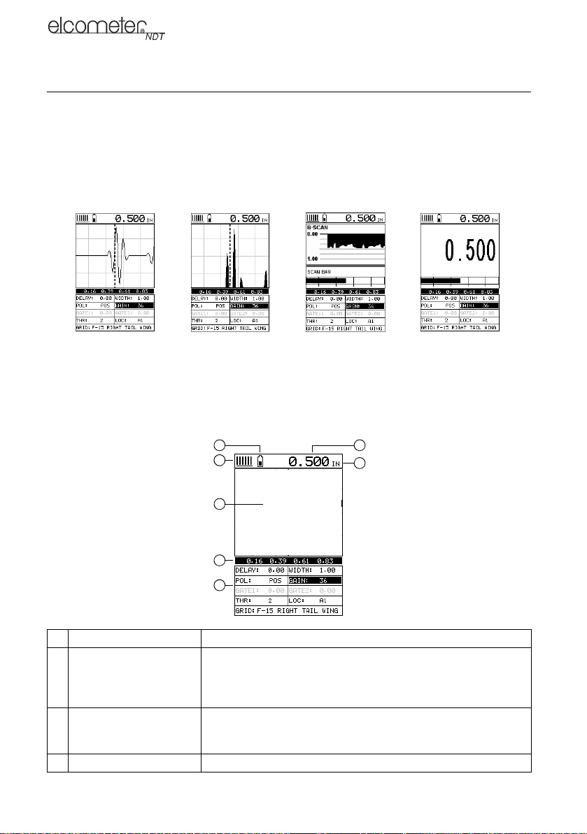
• Change the values of the DELAY and WIDTH functions until the measurement falls inside the
viewable range of the display - see instructions below.
• Use the Auto Find function - see “Auto Find” on page 16.
Note: Even if the waveform is outside of the viewable range of the display, a measurement can be
taken and viewed using the DIGITS view.
5.6.1 DELAY AND WIDTH
The DELAY is the thickness value from which the A-Scan display starts on the left of the screen.
The WIDTH is used to adjust the value at the right side of the screen. Using these two parameters
allows the user to zoom in to a specific measurement range and increase the level of detail on the
display. For example, if a wall thickness was nominally 25mm and an operator was assessing for
corrosion on this wall they might set the DELAY to 10mm and the WIDTH to 20mm to fit as much
relevant information on the display as possible.
B-START and B-DEPTH are analogous to DELAY and WIDTH or a B-SCAN display respectively.
DELAY and WIDTH or B-START and B-DEPTH may be adjusted in the hot menu or in the DISP
section of the main menu.
5.6.2 Adjusting DELAY and WIDTH (or B-START and B-DEPTH)
The quickest way to adjust DELAY and WIDTH is directly from the hot menu. Alternatively, adjust
the values using the menus:
1. Select MENU/DISP/DELAY or WIDTH and adjust using LEFT and RIGHT or press ENTER to
use the DIGITS EDIT BOX
2. Press OK to set the value
3. Press MEAS to return to the measurement.
5.7 GAIN
The gain (the amplitude of the transmitted pulse) can be adjusted to suit a variety of applications.
To obtain valid readings the gain must be set to the correct level to give reliable return echoes:
• Too much gain may result in erroneous measurements by detecting noise rather than the
material back wall itself.
• Not enough gain may result in intermittent detection. It may also result in lack of detection on
internal flaws, pits, or porosity.
The gain setting on your gauge can be compared to the volume control of a home stereo system.
Ifyouturn it up too much you cannot hear the music clearly. If it is turned downtoomuch,youcannot
hear it at all.
Note: When the echo-echo Thru-Paint™ measurement mode is selected, the manual gain feature
is disabled and greyed out in the menu items. In this mode, your gauge switches to an automatic
gain mode (AGC) that optimises the gain setting automatically.
Your gauge has been optimised for a medium gain setting and for the majority of applications it can
be used at this setting. Some applications however may require lower or higher gain settings:
•Lower values might be necessary for noisy or granular cast materials. If the reading becomes
sporadic and will not settle down or resolve on a thickness value.
•Higher values may be necessary when trying to measure a material that is hard to penetrate
(due to the material type, or the overall thickness of the material) and when locating fine pits or
flaws. In these instances, increase the gain until the stability indicator reports a good
measurement.

10
en
5.7.1 To Adjust the Gain Value
The quickest way to adjust GAIN is directly from the hot menu. Alternatively, adjust the value using
the menus:
1. Select MENU/TUNE/GAIN and adjust using LEFT and RIGHT or press ENTER to use the
DIGITS EDIT BOX
2. Press OK to set the value
3. Press MEAS to return to the measurement screen.
5.8 THRESHOLD
The threshold is the level of signal amplitude required to trigger a gate and activate the digital
thickness reading. Increasing the threshold value decreases the sensitivity of the gauge as a more
powerful signal is required to trigger the gate. For example on the A-scan display it may be clear
that there is a flaw in the material but the thickness reading is not taking this into account; lowering
the threshold has the effect of increasing the sensitivity of the gauge to a level that the flaw can be
detected. More information on thresholds can be found on the Elcometer NDT Knowledge Centre
on www.elcometerndt.com
5.8.1 To Adjust the Threshold Value
The threshold value may be adjusted from the hot menu when in the P-E GT or E-E measurement
mode.
5.9 GATES
Your gauge is equipped with gates which control the time measurement process. Further
information on gates can be found on the Elcometer NDT Knowledge Centre on
www.elcometerndt.com.
5.10 .FRONT PANEL LIGHTS
The green light illuminates when the alarm mode is active and the measured thickness is within
limits.
The red light illuminates when the alarm mode is active and the measured thickness is less than
the alarm low value, or the measured thickness is greater than the alarm high value.
6 MEASUREMENT - MODES
To select the measurement mode, press MULTI MODE and select the transducer type and
measurement mode from the list, see “Setting Up the Gauge” on page 12 for details.
The availability of the modes depends upon the type of transducer fitted to the gauge.
6.1 PULSE-ECHO MODE (P-E)
This mode measures from the initial pulse (sometimes referred to as an artificial zero) to the first
echo (reflection). This mode only requires one reflection and it is therefore the most sensitive mode
for measuring weak reflections (flaws) typically found when measuring heavily corroded metals. If
this mode is used to measure a coated sample, then the thickness of the substrate plus coating will
be measured.
6.2 PULSE-ECHO MODE (P-E GT)
This is the same as the standard Pulse-Echo mode described above, but Gate 1 is active.
6.3 ECHO-ECHO MODE (E-E)
This mode measures between two reflections. This technique is commonly used to eliminate errors
from surface coatings and also to make measurements in multiple layered materials. The
disadvantage is that two echoes are needed which requires a much stronger echo (reflection).

11
en
6.4 INTERFACE-ECHO MODE (I-E)
This mode is used with delay line transducers. It measures material thickness from the end of the
interface between probe delay line and material and the back wall of the material. This mode is
similar to the echo to echo mode as two echoes and two gates are required, however they have
different applications.
Interface to echo is mainly used when measuring
thicker materials in the medium to high region of
the measurement range, only the strong interface
echo and the first back wall echo are required.
The second back wall echo is much weaker than
the first due to attenuation, so in thicker materials
it can be lost.
Echo-echo mode is useful for measuring very thin
materials at the lower end of the measurement
range and the back wall echo is less likely to be
lost in the "ring down" or noise from the interface
echo.
The pictures show typical A-scans
when measuring in interface to
echo and echo to echo
respectively. Note how in echo
-echo mode, the first gate is moved
to ignore the first echo from the
end of the delay line. Selecting the
correct measurement mode and
transducer will automatically set
the gate positions and hold-off to
match.
I-E Image Key E-E Image key
A Delay line echo A Gate 1 detect mark
B Gate 1 B Interface echo
C Gate 1 detect mark C Gate 1
D Gate 1 D Gate 2 detect mark
E Gate 2 start E Gate 2 start
F Gate 2 detect mark
Note: The gauge measures the thickness between the
two detect marks
More information on the difference between the Interface to echo and the echo to echo
measurement modes can be found on the Elcometer NDT knowledge centre on
www.elcometerndt.com.
.
.
Transducer
Delay Line
Test Material
Piezoelectric crystal

12
en
7 SETTING UP THE GAUGE
7.1 TRANSDUCER - SETTING TYPE OF
The first step in using your gauge is to select the transducer type from the predefined list of setups
stored in the gauge.
Selecting a transducer type and measurement mode optimises all gauge parameters for that
particular probe.
Once the setup has been selected, your gauge will recall these settings every time it is switched on.
The setup will only change if you select a previously saved setup from the list.
Follow these steps to select your transducer type:
1. Press .
A list of setups of measurement modes and transducers is dis-
played.
2. Use UP and DOWN arrows to scroll through the list until the
appropriate type is highlighted and then press ENTER.
Note: Ensure the transducer type you select is the same as the
transducer plugged into your gauge; failure to do this will result
in erroneous measurements.
3. When the CONFIRM screen displays ‘OVERWRITE CURRENT
SETTINGS’, press OK to overwrite the existing transducer type
with the newly selected transducer type.
You now need to perform a probe zero before taking measurements.
7.2 TRANSDUCER - ZEROING
Note: This function is only used when using a contact style transducer with a pulse-echo contact
setup selected. All the other transducer types use multiple echo modes and the zero function is not
needed.
Setting the zero point for the transducer is important in the same way it is important for a mechanical
micrometer. Zeroing takes into account slight variations in the manufacturing process for maximum
accuracy. If zeroing is not carried out correctly, the measurements taken by the gauge will be in
error by some fixed value.
Note: If you intend to switch between measurement modes, setup up the gauge in pulse-echo
mode, perform the probe zero, and then save the setup to one of the empty setup locations. Once
this is completed, you can switch between modes toggling between two setups.
In order to perform the zero probe routine, your gauge must be in pulse-echo mode.
1. Press MEAS to display the measurement screen.
2. Remove all couplant from the face of the transducer and check that the wearface is clean and
free of any debris.
08/7,
02'(

13
en
3. Apply a drop of couplant on the transducer and place the
transducer as shown in diagram.
Note: Disregard the value displayed; it is not important. What is
important is accurately performing these steps to ensure reliability
of the zero calculation.
4. Select MENU/PROBE/ZERO TRANSDUCER and press ENTER.
The ZERO TRANSDUCER screen is displayed.
5. Press OK (or ESC to cancel).
When the manual probe zero is completed the measurement
screen is displayed.
6. Remove the transducer from the probe zero disk.
Your gauge should now be zeroed.
7.3 CALIBRATING - FOR A MATERIAL
Sound travels through different materials at different speeds, and in
order to measure these materials accurately the correct sound velocity must be programmed into
the gauge. There are three methods of calibrating the gauge.
Known Material Calibration - The material to be measured is selected from a list in the gauge.
Known Velocity Calibration - If the material sound velocity is known this may be entered manually
into the gauge.
Known Thickness Calibration - A sample of the material to be inspected is measured using
alternative means and then used to calibrate the gauge.
•One Point calibration is the simplest and most commonly used calibration procedure with best
performance over large measurement ranges
•Two Point calibration uses two samples of different thicknesses, with enhanced accuracy over
small ranges close to the sample thicknesses used
For the highest measurement accuracy use the known thickness calibration as this takes into
account variation in material composition, temperature and a variety of other factors.
Note: If you create a completely new setup for interface-echo (I-E) mode, a two point calibration
must be performed.
7.3.1 Known Material Calibration
If the material velocity is unknown, and a sample thickness cannot be taken from the material, you
can choose a material type from a list stored in the gauge. For each material stored in the list there
is a corresponding velocity value.
Note: These velocities will not always be an exact representation of the material being tested. Use
these values only if a close approximation is acceptable.
1. Select MENU/CAL/MATERIAL and press ENTER.
2. Scroll through the material list until the appropriate material is highlighted
3. Press ENTER to select the material type followed by OK.
Press MEAS to return to the measurement screen.
To achieve the most accurate measurements possible, it is generally advisable to calibrate the
gauge to a sample piece of known thickness. Material composition (and thus, its sound-velocity)
sometimes varies from lot to lot and from manufacturer to manufacturer. Calibration to a sample of
known thickness will ensure that the gauge is set as closely as possible to the sound-velocity of the
material to be measured.
5
0(18 &/5 0($6

14
en
7.3.2 Known Velocity Calibration
If the material velocity is known, you can enter the velocity value directly into the gauge. For a list
of the sound velocities of common materials see “Sound Velocities of Common Materials” on
page 27
1. Select MENU/CAL/VELOCITY and press ENTER to display the DIGITS EDIT BOX.
2. Adjust to match the material velocity using the LEFT, RIGHT, UP and DOWN arrows then
press OK.
3. Press MEAS to return to the measurement screen.
7.3.3 Known Thickness Calibration
If the sound velocity of a material is unknown, a sample with one or two known thicknesses can be
used to determine the sound velocity.
Note: Although the gauge has a Thru-Paint™/coating feature, known thickness calibration must be
performed on material with the paint or coating removed.
One-point Calibration: The one point calibration option is most suited for linearity over large
ranges. You should always calibrate on high side of the intended measurement range. For example,
if the measurement range is 2.54 mm to 25.4 mm (.100" to 1.0"), you should calibrate on a known
thickness sample close to 25.4 mm (1.0").
Note: Before you start this calibration procedure, perform a probe zero.
1. Apply a drop of couplant on the transducer and place the transducer in steady contact with the
sample or the material being tested. Be sure that the reading is stable and the repeatability
indicator, in the top left corner of the display, is fully lit and stable.
2. Select MENU/CAL/ONE POINT and press ENTER to display the DIGITS EDIT BOX.
3. Adjust to match the material thickness using the LEFT, RIGHT, UP and DOWN arrows.
4. Press OK to calculate the velocity and return to the measurement screen, or ESC to cancel.
Note: Place the transducer back on the calibration point. The thickness reading should now match
the known thickness but if outside tolerance, repeat the steps above.
Two-point Calibration: For improved accuracy over a smaller measurement range, conduct
one-point calibration followed by a two-point calibration. For example, if the measurement range is
2.03 mm to 6.35 mm (.080" to 0.250"), perform a one point calibration on a known thickness sample
close to 6.35 mm (.250"), followed by a two-point calibration close to 2.03 mm (.080").
1. Conduct a one point calibration routine as described previously in this section. You should
conduct this routine at the high end of the measurement range
2. Repeat the routine with another sample at the low end of the measurement range, except this
time enter the thickness into the TWO POINT area in the CAL menu.
Note: CHECK YOUR CALIBRATION. Place the transducer back on both calibration points. If the
thickness is out of tolerance repeat the steps above.
8 MEASUREMENT - TAKING READINGS
Disclaimer: Inherent in ultrasonic thickness measurement is the possibility that the instrument will
use the second rather than the first echo from the back surface of the material being measured. This
may result in a thickness reading that is TWICE what it should be.
Responsibility for proper use of the instrument and recognition of this phenomenon rests solely with
the user of the instrument.
Other errors may occur from measuring coated materials where the coating is insufficiently bonded
to the material surface. Irregular and inaccurate readings may result. Again, the user is responsible
for proper use and interpretation of the measurements acquired.

15
en
8.1 BEFORE YOU START
• Prepare the surface.
• Ensure the correct transducer is selected and set in the gauge.
• Select the correct measurement mode - see “Measurement - Modes” on page 10.
• Set the zero point of the transducer,if necesssary - see:
• “Transducer - Zeroing” on page 12 and
• Calibrate the gauge - see:
• “Calibrating - for a Material” on page 13 and
• Choose the measurement view (DIGITS, RF or RECT, or B-SCAN) - see “The Measurement
Screen” on page 7.
8.2 PROCEDURE
1. Apply couplant
For the gauge to work correctly there must be no air gap between the transducer and the
surface of the material to be measured. This is achieved using a couplant.
Before the transducer is placed on the surface, put a small amount of couplant supplied with
the gauge on the surface of the material. Typically a single drop is sufficient.
2. Place transducer onto the surface of the material to be measured
Press the transducer wearface into the couplant. Only moderate pressure is necessary to
keep the transducer stationary and the wearface seated flat against the surface of the
material.
3. Read display
If six or seven bars of the stability indicator are showing, the display will be reading the correct
thickness of the material directly beneath the transducer.
If the stability indicator has fewer than five bars showing, or the numbers on the display seem
erratic, check to make sure that there is an adequate film of couplant beneath the transducer,
and that the transducer is seated flat against the material. If the condition persists, it may be
necessary to:
• adjust the gain, or
• select a different transducer (size or frequency) for the material being measured.
The gauge will perform a number of measurements every second when the transducer is in
contact with the surface of the material. The display is updated as each reading is taken.
4. Remove transducer from surface
The display will show the last measurement made.
Note: Occasionally, a small film of couplant will be drawn out between the transducer and the
surface as the transducer is removed. When this happens, the gauge may perform a measurement
through this couplant film. This phenomenon can be seen when one thickness value is observed
while the transducer is in place, and another value is observed after the transducer is removed. If
this happens, take the reading again using less couplant.
9 GATES
9.1 INTRODUCTION
The Model PG70ABDL is equipped with gates which control the time measurement process
allowing you to measure a specific region on or between waveforms.
Further information on gates may be found on the Elcometer NDT Knowledge Centre on
www.elcometerndt.com.

16
en
9.2 ADJUSTING THE GATES
In P-E GT mode one gate is available and may be adjusted from the hot menu. In E-E mode both
gates may be adjusted from the hot menu or alternatively select MENU/GATE.
10 THRU-PAINT™ MEASUREMENT TECHNIQUE
10.1 INTRODUCTION
Your gauge is equipped with a Thru-Paint™measurement mode that uses a multiple echo
technique to allow measurement of the material thickness beneath a coating. This is useful for
checking the material thickness of painted object.
Thru-Paint™ capability is available in E-E mode, to activate Thru-Paint™ operation select this
measurement mode using the MULTI MODE key and a delay line transducer.
Further information may be found on the Elcometer NDT Knowledge Centre on
www.elcometerndt.com.
11 MEASUREMENT - OPTIONS
11.1 AUTO FIND
When using a scan type display, the DELAY and WIDTH (or B-START and B-DEPTH) must be set
correctly for the waveform to be shown on the display. If these parameters are set up incorrectly
nothing will be seen. The AUTO FIND function solves this problem by automatically adjusting these
parameters so that the relevant part of the waveform is shown on the screen.
To use the AUTO FIND function place the transducer on the material to obtain a reading, select
MENU/UTIL/AUTO FIND.
11.2 HIGH SPEED SCAN
Although your gauge excels at making single point measurements, it is sometimes desirable to
examine a larger region, searching for the thinnest point. The gauge includes a feature, called Scan
Mode, which allows it to do just that.
This mode increases the overall repetition rate to a maximum of 32 Hz with a high speed screen
refresh rate of 25 times a second.
This feature enables the user to make scanned passes over an arbitrary length of the test material
while still maintaining a reasonable representation of thickness over the scanned area or region.
This feature can be used in conjunction with High and Low alarm limits features to keep track of
both values dynamically.
To enable/disable the high speed Scan Mode:
1. Select MENU/UTIL/SCAN MODE.
2. Use the LEFT and RIGHT arrows to toggle the SCAN MODE on/off.
3. Press MEAS to return to the measurement screen, ready to begin taking readings.
11.3 ALARM MODE
Your gauge includes an Alarm Mode. Set the limits, and if a measurement falls outside of these
limits your gauge will signal an alarm (a red light on the front panel of the instrument and/or an
audible beep).
This feature may be used for a variety of applications to verify the material is within the manufacturer
specifications.
There are two limit values, ALARM LOW and ALARM HIGH. You can choose to activate both or
just one of these values depending on your requirements.

17
en
To enable/disable Alarm Mode:
1. Select MENU/UTIL/ALARM STATUS
2. Use the LEFT and RIGHT arrows to toggle the ALARM on/off/audible.
3. Press MEAS to return to the measurement screen, ready to begin taking readings.
To set the Alarm limits:
1. Select MENU/UTIL/ALARM LO LIMIT or ALARM HI LIMIT and press ENTER to display the
DIGITS EDIT BOX.
2. Adjust to suit the measurement application using the LEFT, RIGHT, UP and DOWN arrows.
3. Press OK to set the alarm value and return to the menu screen, or ESC to cancel.
4. Press MEAS to return to the measurement screen.
11.4 POLARITY
The polarity that your gauge detects on can be set to either positive or negative to obtain the best
detection results depending on the specific measurement conditions of your application. Polarity
affects both the gate (above or below the x axis in the RF A-Scan) and the Rectified A-Scan display
(whether the top or bottom half of the RF display is shown).
For further information refer to the Elcometer NDT Knowledge Centre on www.elcometerndt.com.
To adjust POLARITY:
1. Set the measurement screen view to RF, MENU/DISP/VIEW.
2. Select MENU/TUNE/POLARITY.
11.5 RECTIFIED WAVEFORM DISPLAY OPTIONS
When the measurement screen is set to RECT, you have the option of displaying the waveform
filled in black, or outlined (unfilled).
To set this option:
1. Press MENU, select DISP, select VIEW and then select RECT to set the RECT display view.
2. Press MENU, scroll to the TUNE menu and then highlight the RECT WAVEFORM function.
3. Use LEFT and RIGHT arrows to adjust the value of RECT WAVEFORM (FILLED, OUTLINE).
4. Press MEAS to return to the measurement screen.
Your gauge is equipped with a data logger. With a data file open, all your measurements are saved
into the file for later review and download to PC.
11.6 ABOUT THE DATA LOGGER
With a data file open, as you take measurements, the measurement data is stored in files in the
gauge memory in Grid format similar to a spreadsheet format in which each cell is used to store a
reading. Cells are referenced by the row number (1 to 999) and the column label (A to ZZ).
Data logger filename character sets
Any combination of the following characters can be used for file names:
• Numeric characters: 0 - 9
• Alpha Characters: A - Z
• Special Characters: ! ' _ # space / . - ( )
What measurement data is saved
When a measurement is taken (irrespective of log file format), the following information is saved:
• The reading value.
• A screenshot, the nature of which will depend on what view the gauge was in at the time the
reading was taken. For example, if the view was in B-SCAN, then a B-SCAN screenshot will
be saved with the reading. This 'Save Graphics' option can be toggled on/off.

18
en
Memory capacity
You can create and save as many data files as required up to the maximum capacity of the gauge
memory (32 Mbit). If you try to create a new file which exceeds the memory capacity, the gauge will
display an error message. Saved data must be deleted in order to make the space available.
11.7 CREATING A NEW DATA LOGGER FILE - GRID FORMAT
To create a GRID log data file:
1. Select MENU/DATA/NEW and press ENTER to continue
2. Fill in a name and a note (if desired) for your data logger file
3. Select the size of the grid. Grid positions are denoted by a number and a letter, where the
letter is the column and the number is the row.
Use TOP LEFT and LOWER RIGHT to define the size of the grid. For example, a with the TOP
LEFT set to A001 and LOWER RIGHT C003 would produce a 3x3 grid
The grid can have a maximum of 52 columns and 999 rows
4. Set the Auto Increment direction. This option allows you to select which direction the cursor
moves after a reading is stored in terms of compass points. For example NORTH would move
the cursor up a row, and WEST would move a column left.
5. Choose whether to activate SAVE GRAPHICS or not (snapshot of the A OR B scan on
screen).
6. Finally create the log by scrolling to CREATE LOG, pressing ENTER and then OK to confirm.
The measurement grid is now displayed along with the grid name on screen.
11.8 HANDLING LOGGER FILES
Once created, logger files may be opened or closed using the functions "OPEN" and "CLOSE"
Closing logger files places the gauge in immediate mode and will prevent accidental saving of data
into an inappropriate log.
11.9 STORING READINGS IN A DATA LOGGER FILE
1. Create a new data logger file or open an existing file.
The grid is displayed in the lower half of the measurement screen.
Note: Once the file is open, it will remain open until it is closed or another file is opened. If the
gauge is switched off, the file will be opened automatically when the gauge is switched on
again. Press the ENTER key to display the file from the measurement screen.
2. If you want to save the reading to a particular cell location, scroll to the desired cell.
Note: The cell location must be empty. If it already contains a reading and you want to save a
new reading to the same location, refer to the instructions given in “Viewing and Deleting
readings” on page 19.
3. Take a reading and then press ENTER.
The reading value is saved in the file at the location selected and the cursor advances to the
next cell according to the rules set for the data logger file:
• If INCR. DIR is set to NORTH, EAST, SOUTH or WEST, the cursor will advance one cell in
the chosen direction. When the cursor reaches the last cell in the row or column it will
return to the other end of the row or column.
Save Graphics Option Memory Capacity
(readings)
On 12 000 +
Off 210 000 +

19
en
Note: If you try to save a reading into a cell location which already contains a reading value, a
warning message is displayed (see Deleting a reading).
4. To advance to a specific row number, press OK enter the row number. Press OK to advance
directly to that row number in the grid log.
5. To toggle the display between DIGITS view and B-SCAN view, press ESC.
6. If you are unable to take a measurement due to the measurement location being physically
inaccessible, press CLR.
The cell location in the data file is marked OBST (Obstruct).
7. The display of the log data file on the measurement screen can be switched on and off:
• To switch off, press MEAS
• To switch on, press ENTER.
11.10 VIEWING AND DELETING READINGS
With a data file open:
1. Use the arrows to scroll through the cells in the data file.
As the cursor is moved to a different cell, the display is updated with the display view saved
with the reading (if SAVE GRAPHICS was set to YES). Readings stored in memory are
indicated by MEM in the top left corner of the measurement screen (in place of the bars of the
stability indicator).
2. To delete a reading, scroll to the cell location, press CLR and then OK (or ESC to cancel).
The reading is deleted and if you wish you can now take another measurement and save the
reading in this cell location.
11.11 EDITING A DATA LOGGER FILE
You can edit the following fields of data files:
• NAME, NOTE, and INCRement DIRection
To edit a file:
1. Open the data file. (Select MENU/DATA/OPEN)
2. Select MENU/DATA/EDIT and press ENTER
The EDIT GRID screen is displayed and lists all the fields which can be edited.
3. Scroll to the field you want to edit, press ENTER and then adjust the contents of the field using
the techniques previously described to create a data file - see page 18.
4. When finished, scroll to SAVE CHANGES, press ENTER and then OK (or ESC to cancel).
11.12 DELETING A DATA LOGGER FILE
1. Select MENU/DATA/DELETE ONE GRID and press ENTER.
The DELETE GRID screen is displayed and lists all the data files stored in your gauge
memory.
2. Scroll through the list until the data file you want to delete is highlighted.
3. Press OK (or ESC to cancel).
The file is deleted.
11.13 DELETING ALL DATA LOGGER FILES
Note: This will delete all the data logger files in gauge memory - use with caution.
1. Select MENU/DATA/DELETE ALL GRIDS
2. Press ENTER and then OK to confirm (or ESC to cancel).
The data logger memory is erased - all files are deleted.
Table of contents