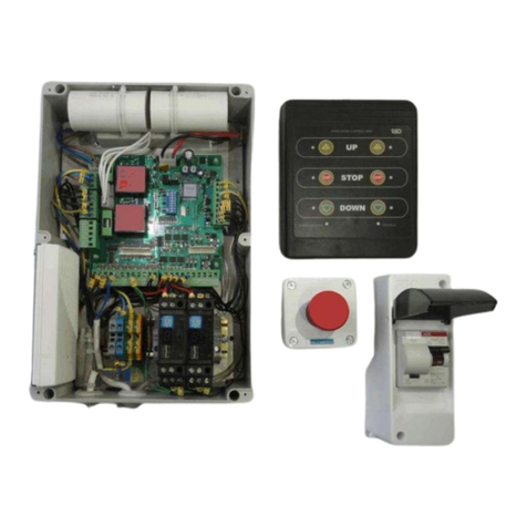
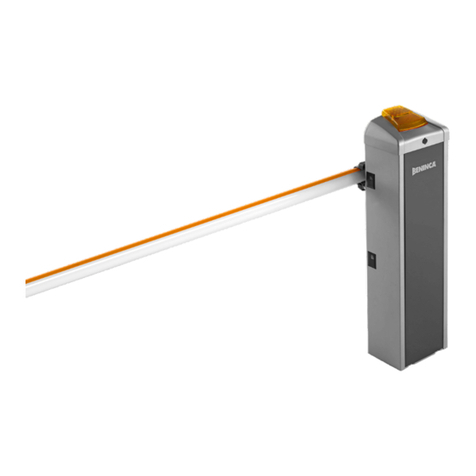
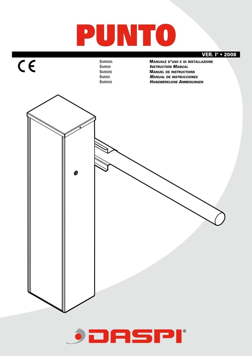
Tiso Optimus 40 User manual

series of RB396-03, RB396-04, RB396-05, RB396-06
AUTOMATIC BOOM BARRIER OPTIMUS
OPERATION MANUAL. PART І
Original guide
Page
-1-
Size А4
Installation and Operation Manual
Revision 1.0 2021
ROAD BLOCKING SYSTEMS
Office and Production site: Tel.: +380 (44) 291-21-11
14 Promyslova str., 02088, Kyiv, Ukraine, Fax: +380 (44) 291-21-02
E-mail: [email protected] www.tiso.global
BOOM BARRIER OPTIMUS

џR.s.l - Road surface level (reference point + 0.000).;
џM - Maintenance
џIR - infrared safety sensors;
џThis Manual is an integral part of the product and shall be handed over to the customer. The Manual
shall be kept for future use and to be consulted, if appropriate.
џIf the Boom barrier is resold, handed over to another owner or transported to another place, make
sure that this manual is enclosed to the product to be used by new owner and/or maintenance staff
during installation and/or operation.
џOM-Operation Manual;
џACS - access control system;
The following abbreviations are used in this Manual:
7.1 Main connection of boom barrier.......................................................................................................
8. Precommissioning...................................................................................................................................
7.2 Connection of barrier arm lighting......................................................................................................
7.3 Installation and connection of IR barriers (safety sensors)...............................................................
3. Product Purpose ......................................................................................................................................
1.1 Instruction for installers.....................................................................................................................
4.2 Overall dimensions...........................................................................................................................
6. Installation of boom barrier.......................................................................................................................
8.1 Preparation for precommissioning.....................................................................................................
7. Connection of boom barrier utilities..........................................................................................................
5.2 Key elements of boom barrier............................................................................................................
5.1 Recommended Scope of Delivery.....................................................................................................
5.3 Boom Barrier mechanism design......................................................................................................
5. Product specification ................................................................................................................................
Contents:
4.1 Technical features of boom barrier “Optimus”...................................................................................
4. Technical Specifications............................................................................................................................
2. Description ................................................................................................................................................
1. General Guidelines..................................................................................................................................
1.2 Instruction for users...........................................................................................................................
DECLARATION OF CONFORMITY OF EQUIPMENT ..........................................................................
8.2 Precommissioning.............................................................................................................................
8.3 Controlling the operation of boom barrier...........................................................................................
9.1 Spring replacing................................................................................................................................
9.2 Possible malfunctions .......................................................................................................................
10.Boom barrier operation regulations..........................................................................................................
9. Routine maintenance................................................................................................................................
10.2 Equipment maintenance.................................................................................................................
10.3 Safety regulations............................................................................................................................
10.1 Rules of operations .........................................................................................................................
11. Notes.......................................................................................................................................................
6.6 Versions of Boom barrier "Optimus" .................................................................................................
6.5 Manual control ..................................................................................................................................
6.4.3 Arm position adjustment.........................................................................................................
6.1 Preliminary check..............................................................................................................................
6.4.2 Arm balancing.........................................................................................................................
6.2 Tools .................................................................................................................................................
6.3 Preparation of bottom plate and installation of barrier cabinet..........................................................
6.4 Barrier arm mounting ........................................................................................................................
6.4.1 Barrier arm installation............................................................................................................
11
10
9
9
9
7
7
6
6
5
4
4
3
13
14
17
13
16
11
20
23
22
24
21
20
20
20
11
19
19
18
18
15
21
22
22
23
21
12
Page
-2-
Size А4
Installation and Operation Manual
Revision 1.0 2021
ROAD BLOCKING SYSTEMS
Office and Production site: Tel.: +380 (44) 291-21-11
14 Promyslova str., 02088, Kyiv, Ukraine, Fax: +380 (44) 291-21-02
E-mail: [email protected] www.tiso.global
BOOM BARRIER OPTIMUS

There is confirmed the compliance with the basic safety requirements of following EU
Directives: 2006/42/ EC, 2014/30/EC, 2014/35/EC.
DECLARATION OF CONFORMITY OF EQUIPMENT
Page
-3-
Size А4
Installation and Operation Manual
Revision 1.0 2021
ROAD BLOCKING SYSTEMS
Office and Production site: Tel.: +380 (44) 291-21-11
14 Promyslova str., 02088, Kyiv, Ukraine, Fax: +380 (44) 291-21-02
E-mail: [email protected] www.tiso.global
BOOM BARRIER OPTIMUS

1. General safety provisions
џIt is forbidden to make changes to the arrangement of equipment and use of materials and
components that are not included in scope of delivery and are not provided for in this
Manual.
џSafety devices shall protect potentially hazardous areas.
џIn the case of violation of the operating rules and the requirements of the operational
documentation, the boom barrier may pose no hazard to life and health by virtue of high
voltage and moving parts of the product!
џPersonnel involved in maintenance of existing electrical installations or commissioning,
electrical installation, repair work, maintenance and installation shall be trained to work
with this model of the device! Training shall be carried out at the manufacturer's represen-
tatives' or at the manufacturers' of the product.
џDo not allow children and unauthorized persons to stay near operating equipment. The manufacturer shall bear
no responsibility for violation of safety rules.
The Manual should be scrutinized prior to the equipment installation and operation to ensure
the human safety. Safety is not ensured in case of improper operation or use.
џTiSO Company ensures its best effort for guarantee and correctness of this Manual and reflecting material
changes in the design. However, a policy of continuous improvement can lead to insignificant differences
between the equipment supplied and the description in this document.
џAny actions that are not explicitly listed in these instructions shall be prohibited.
џThe Manual to be kept for future use.
џTransportation of the product shall be ensured only with the barrier arm removed!
1.1 Instructions for installers:
1. For your safety, follow the installation instructions;
2.The product shall be installed in accordance with applicable regulations and rules, in compliance with safety
precautions during installation work;
3. Installation of the equipment shall be carried out with the power supply disconnected;
4. Packaging materials shall be disposed in accordance with applicable standards;
5. Strictly observe the sequence of operations for assembling the boom barrier specified in the instruction;
9. Appropriate warning signs, operating in the territory of the country, shall be placed on the section of traffic
regulated by boom barrier!
џDo not install this equipment during a lightning storm, heavy rain or snow, in an explosive
atmosphere and in poor visibility. Mounting zone is equipped according to the current
standards.
џBoom barrier installation, connection and commissioning works shall be performed by
specialists of the appropriate qualification.
6. If faults or defects are detected, contact the supplier's service service.
7. The installer shall provide the user with the necessary information on the operation of the system in manual mode
in case of an emergency.
8. Before handing over the product to the end user, check consistency of product indicators. Make sure that the
automation, security and unlocking of drive configured correctly.
The manufacturer is not responsible for the operation of equipment in the following cases:
џnon-compliance with the installation technology,
џuse of non-standard materials and components,
џperformance of work by unqualified personnel,
џmanufacturer is not responsible for the safety measures when installing the equipment by personnel not
involved in the company service department.
Page
-4-
Size А4
Installation and Operation Manual
Revision 1.0 2021
ROAD BLOCKING SYSTEMS
Office and Production site: Tel.: +380 (44) 291-21-11
14 Promyslova str., 02088, Kyiv, Ukraine, Fax: +380 (44) 291-21-02
E-mail: [email protected] www.tiso.global
BOOM BARRIER OPTIMUS

1.2 Instructions for users:
1.For your safety, follow the installation instructions;
2.It is forbidden to make changes to the arrangement of equipment;
3.Strictly observe the sequence of operations for assembling the boom barrier specified in the Manual;
4.Do not attempt to repair or configure the boom barrier yourself, please contact the appropriate service
Breaking of seals cancels the guarantee obligations of the manufacturer.
5.The control points (conrol panels) of the boom barrier shall be inaccessible to outsiders.
6.TiSO Company is not responsible for incorrect operation of the equipment, violation by user of security
measures;
џThe boom barrier must be installed, precommissioned and serviced by the certified
professionals having the relevant qualification and being familiar with Manuals and product
documentation such as:
- Installation and operation manual (Part І, Part ІІ);
- Technical passport;
- Instruction manuals for components.
џTechnical inspections, maintenance, adjustment and repair shall be performed only when
the boom barrier is deenergized.
џThe product designed and manufactured in accordance with directives of the European
Union, shall be marked according to CE standards.
Page
-5-
Size А4
Installation and Operation Manual
Revision 1.0 2021
ROAD BLOCKING SYSTEMS
Office and Production site: Tel.: +380 (44) 291-21-11
14 Promyslova str., 02088, Kyiv, Ukraine, Fax: +380 (44) 291-21-02
E-mail: [email protected] www.tiso.global
BOOM BARRIER OPTIMUS

џreflective stickers for arms
џtraffic light, etc.
2.1 Electro-mechanical boom barrier “Optimus” is intended for arrangement and control of vehicle
passageway width up to 6m.
2.2 Boom barrier “Optimus” has a reliable simple structure, the main elements of which are a stand with a
power-operated mechanism, an barrier arm and an electronic control unit. Boom barrier is balanced by
tension/compression of spring and depends on the arm length and accessories installed on it.The drive design
allows to use a 4m barrier arm without use of support and a 6m barrier arm with a support.
2.3The barrier may be operated from:
џwired or wireless remote control;
џautomatic access control system (access cards, exit buttons);
џmanual (in case of power failure the boom barrier can be operated manually)
2.4 Coating - black and orange paint ;
2.5 A wide range of accessories is available for convenient use:
џLED lighting of Barrier arm
џIR barriers (safety sensors)
џinduction loops
џarm support post
to sports facilities and governmental facilities, to be installed in front of shops, hotels,shopping
malls and office centers, health care facilities, at the approaches to cottages and cottage
settlements, at central urban and historical sites, industrial and special facilities.
3.1 The electromechanical barrier “Optimus” is intended to restrict access to territory with
high traffic intensity and width of passage up to 6 meters. The “Optimus” barrier is used at state,
commercial and private facilities to restrict unauthorized entry and exit of vehicles, to regulate
and arrange traffic of road transport at facilities and adjacent territories. These can be automated
parking zones, customs terminals, etc.
3.2 The Boom Barriers are recommended for passenger transport facilities, in the driveway
3.3 The Boom Barriers can be installed along with other traffic control and unauthorized
access prevention equipment.
3.4 By impact of environmental factors the Boom Barrier complies with EN 300 019-1-4
and is designed for outdoor operation in temperate conditions with permissible ambient
temperature - 10°С to +40°С.
2. Description
3. Product Purpose
OFFICE
BUILDINGS
PLANTS
SPORTS AND
LEISURE CENTERS
HAULAGE
COMPANIES
PPP
PARKING LOTS
Page
-6-
Size А4
Installation and Operation Manual
Revision 1.0 2021
ROAD BLOCKING SYSTEMS
Office and Production site: Tel.: +380 (44) 291-21-11
14 Promyslova str., 02088, Kyiv, Ukraine, Fax: +380 (44) 291-21-02
E-mail: [email protected] www.tiso.global
BOOM BARRIER OPTIMUS

4.
4.1 Technical features of boom barrier “Optimus”
Boom barrier
“Optimus 40”
“Optimus 60”
Model
RB396-03
RB396-04
RB396-05
RB396-06
Installation type automatic electro-mechanical
Operation mode left/right version
Arm length 3 m 4 m 5 m 6 m
Overall dimensions of
Boom barrier with arm 448х3010х1005mm 448х4010х1005mm 448х5010х1005mm 448х6010х1005mm
Dimensions of cabinet 310 х 358 х 1005 mm
Barrier arm round section Ж 90 mm
Barrier arm height position 840 mm
Weight 80 kg 82 kg 86 кg 88 kg
Power consumption 150 W
Operating voltage 50/60 Hz; 1ph-230V
Opening / Closing time 4 s (± 1 s) 6 s (± 1 s)
Protection level IP 54
Temperature range standard - 10° C / +40 ° C
Temperature range** optional - 40° C / +60 ° C
Noise level < 70 dB
Operation frequency 200 cycles/hour 170 cycles/hour
Usage rate 70% 30%
Cabinet material brushed stainless steel AISI 430
Housing/ Colour powder coated/ orange RAL 2004, black RAL9005
Arm barrier material powder coated aluminium RAL 9010
LED indicatiion
Double-sided RYG light indication (in cabinet)
Raised position locking gear motor
Manual operation manual release mechanical device
* Technical features can be changed without prior notice;
** For temperatures below -10 °C heating system to be used / for temperatures above +40 °C cooling system to be used
Additional options:
Arm support post +
Reflective stickers for arm +
Bottom plate +
IR barrier (safety sensors) +
Set of posts for IR barriers +
Arm lighting (RYG) +
Induction loop kit +
Traffic light +
Post for traffic light +
Cooling system +
Heating system +
Remote control industrial IP54 +
Radio control kit RX - 2K +
Additional remote keyfob T-2 +
Technical Specifications
Table 1- Technical features of boom barriers
Table 2- Supplementaries for boom barriers
Page
-7-
Size А4
Installation and Operation Manual
Revision 1.0 2021
ROAD BLOCKING SYSTEMS
Office and Production site: Tel.: +380 (44) 291-21-11
14 Promyslova str., 02088, Kyiv, Ukraine, Fax: +380 (44) 291-21-02
E-mail: [email protected] www.tiso.global
BOOM BARRIER OPTIMUS

4.2 Overall dimensions RB396 ( for road width from 1 m to 6 m)
796 mm
1650 - 5650 mm
308 mm
90 mm
1005 mm
2010 - 6010 mm
1650 - 5650 mm
448 mm
358 mm
448 mm
300 mm
308 mm
А
View А
306 mm
236 mm
350 mm
Ø 13 mm
4 holes
Ø 60 mm
Cable input
22 mm
150 mm
175 mm
42 mm
Page
-8-
Size А4
Installation and Operation Manual
Revision 1.0 2021
ROAD BLOCKING SYSTEMS
Office and Production site: Tel.: +380 (44) 291-21-11
14 Promyslova str., 02088, Kyiv, Ukraine, Fax: +380 (44) 291-21-02
E-mail: [email protected] www.tiso.global
BOOM BARRIER OPTIMUS

Page
-9-
Size А4
Installation and Operation Manual
Revision 1.0 2021
ROAD BLOCKING SYSTEMS
Office and Production site: Tel.: +380 (44) 291-21-11
14 Promyslova str., 02088, Kyiv, Ukraine, Fax: +380 (44) 291-21-02
E-mail: [email protected] www.tiso.global
BOOM BARRIER OPTIMUS
27
3
6
5
1
8
10
9
4
5.1 Recommended Scope of Delivery:
Legend:
1. Boom barrier
2. Arm
3. Cabinet lid
4. Bracket for arm fixation
5. Cabinet indication
6. Logo
7. Reflective stickers for arm
8. Lock
9. Door
10. Ventilation grate
11. Arm support post
12. Arm lighting (RYG)
After the Boom Barrier is received it is to be unpacked and inspected to be sure that the Boom Barrier is not
damaged. If any damage is found then the Road Barrier supplier to be contacted.
Recommended scope of delivery for Boom Barrier specified in Table below:
Item
Quantity
Barrier cabinet “OPTIMUS” with built-in control unit 1pc
Barrier arm d90 1 pc
Arm support post 1 pc
Wired control panel (IP41) RB111 1 pc
Anchor redibolt HST3 M12x165 4 pcs
IR barrier set of 2 pcs
Red reflective stickers for arm 1 set
Key for door 1 set
5.2 Key elements of boom barrier:
5. Product specification
11
12
* boom barrier from side of
protected area
Table 3- Recommended Scope of delivery

5.3 Boom Barrier mechanism design
The picture below shows the structure of right-hand boom barrier mechanism, barrier arm is in the
horizontal position, the sector of the mechanism is in the upper position, the spring is in the compressed state.
11 12
13
14
15
6
2
5
10 9
8
7
4
3
1
Legend:
1. Boom barrier cabinet;
2. Barrier arm;
3. Protective housing of spring;
4. Electronic control unit;
5. Cabinet lid;
6. Cabinet light indication;
7. Manual operation (emergency release);
8. Gear motor;
9. Gear motor lever;
10,11 Upper and lower arm movement restrictor;
12. Magnet;
13. Excentric load;
14. Chain;
15. Sector (balancing lever)
* boom barrier from protected area side
Page
-10-
Size А4
Installation and Operation Manual
Revision 1.0 2021
ROAD BLOCKING SYSTEMS
Office and Production site: Tel.: +380 (44) 291-21-11
14 Promyslova str., 02088, Kyiv, Ukraine, Fax: +380 (44) 291-21-02
E-mail: [email protected] www.tiso.global
BOOM BARRIER OPTIMUS

6. Installation of boom barrier
Left version boom barrier Right version boom barrier
cabinet door cabinet door
џArrangement of installation site must comply with requirements of the applicable regulations and
standards.
џInstallation area shall be fenced along perimeter with temporary security fencing or caution tape
at the distance of 3 meters from the installation site.
џThe appropriate warning signs ISO 7010:2011 shall be installed in front of the installation site.
џKeep outsiders away from the installation site!
џSafety regulations must be observed during installation!
6.1 Preliminary check
Make sure that the following conditions are met to ensure safe and reliable operation of the Boom
Barrier:
џThe installation site soil should provide high stability of the base plate.
џThe boom should not be in contact with foreign objects (e.g. tree branches) along the entire move-
ment and should move at least 2 m apart overhead power transmission lines.
џMake sure that there are no underground utilities at the installation site!
џNo underground pipes and/or cables to be available within the excavation area for the base plate
installation.
џIf there is a risk of damage of the Boom Barrier body by passing vehicles, then the required precau-
tionary measures to be taken, if applicable, to protect it from impacts.
џThe Boom Barrier rack to be securely grounded to ensure electrical safety.
џThe Boom Barrier installation requires preliminary pulling of electric cables and, if necessary, laying
of the base plate.
- if the cabinet is on the right, it is a right version of boom-barrier.
Prior to installation make sure of availability
of all necessary tools and materials, ensuring the
system installation in full accordance with the
applicable safety regulations.
Note to boom barrier installation:
The barrier may be used exclusively for the passage of vehicles. Pedestrians shall not pass under
a moving arm. A passage suitable for pedestrians should be provided. This passage shall be indicated
by a special sign;
The cabinet door shall be located on the inside of the territory. If you are in the centre of the pas-
sageway, turn towards the outside:
- if the cabinet is on the left, it means it is a left version of boom-barrier,
6.2 Tools
The minimum kit of the required installation
tools is shown in Figure below.
Page
-11-
Size А4
Installation and Operation Manual
Revision 1.0 2021
ROAD BLOCKING SYSTEMS
Office and Production site: Tel.: +380 (44) 291-21-11
14 Promyslova str., 02088, Kyiv, Ukraine, Fax: +380 (44) 291-21-02
E-mail: [email protected] www.tiso.global
BOOM BARRIER OPTIMUS

Barrier cabinet
Concrete
base
Corrugated pipe for
communications
Anchor redibolt
М12х165
Concreted
pit
Bottom
plate
Corrugated pipe for
communications
Washer and
nut (4 pairs)
Communication
input
Cabinet
Concreting to be carried out in accordance with existing standards
The required electrical cables must be routed out of the concrete base.
џPlace the barrier cabinet on the concreted bottom
plate fix and with nuts.
џLevel the horizontally with the help of bottom plate
the building level;
џConcrete the ;bottom plate
џInstall a corrugated pipe for communications for
laying electrical cables;
џDig a pit for the ;bottom plate
Option 2 - Laying the bottom plate for foundation
4) The Boom Barrier cabinet to be installed and anchor
nuts to be screwed.
3) The cabinet to be oriented correctly, and levelled by
means of builder's level, anchor (M12x165) holes for
high performance concrete expansion to be marked and
drilled along the perimeter.
2) The barrier cabinet is fixed to the foundation by
means of anchor bolts. The depth of concreting depends
on the softness of soil and on the depth of soil freezing
(160–500 mm).
1) Dig the ground for concrete base, prepare the
corrugated hoses necessary for making connections for
the subsequent routing of cables in them (the required
number of channels depends on the type of installation
and the connected accessories).
Option 1 -Cabinet fastening
There are two ways to mount a barrier cabinet on the site:
It is recommended to install barrier cabinet in such a way that cabinet door to be opened from the
protected area.
The ground on the installation site shall be sufficiently stable for installation of boom barrier. If the
stability of the soil is unsatisfactory, increase the depth of pit as recommended by the specialists.
6.3 Preparation of bottom plate and installation of barrier cabinet
150-500
Cabinet
±0,000 R.s.l.
Concrete
base
Page
-12-
Size А4
Installation and Operation Manual
Revision 1.0 2021
ROAD BLOCKING SYSTEMS
Office and Production site: Tel.: +380 (44) 291-21-11
14 Promyslova str., 02088, Kyiv, Ukraine, Fax: +380 (44) 291-21-02
E-mail: [email protected] www.tiso.global
BOOM BARRIER OPTIMUS

Page
-13-
Size А4
Installation and Operation Manual
Revision 1.0 2021
ROAD BLOCKING SYSTEMS
Office and Production site: Tel.: +380 (44) 291-21-11
14 Promyslova str., 02088, Kyiv, Ukraine, Fax: +380 (44) 291-21-02
E-mail: [email protected] www.tiso.global
BOOM BARRIER OPTIMUS
М10х100
Mounting bracket
М10х16
Barrier Arm
Arm holder
Shaft of mechanism
5) Connect the (see section 7)electronic control unit
6) Give the “Open” command to raise the barrier arm from the control panel
to check the verticality.
In the end positions of the barrier (open / closed), the barrier arm must
be strictly vertical and horizontal. Alignment is achieved by adjusting
the positions of the mechanical stops. (see clause 6.4.3).
2) Press by bracket and fix barrier arm by bolts M10x100 (2 pcs);
3) Four M10x16 bolts shall be mounted on the edges of mounting bracket.
6.4 Barrier arm mounting
6.4.1 Barrier arm installation
1) Place the barrier arm on the holder and on the shaft of mechanism;.
Make sure that arm is in a horizontal position
Before installing the barrier arm, it is recommended to connect arm lighting (if arm lighting is
provided in the order (see section 7);
Make sure the barrier arm is in the upright position.

Page
-14-
Size А4
Installation and Operation Manual
Revision 1.0 2021
ROAD BLOCKING SYSTEMS
Office and Production site: Tel.: +380 (44) 291-21-11
14 Promyslova str., 02088, Kyiv, Ukraine, Fax: +380 (44) 291-21-02
E-mail: [email protected] www.tiso.global
BOOM BARRIER OPTIMUS
Always turn off the electricity when setting up the boom barrier!
1) cabinet door to be opened with key from the kit;
2) set the barrier arm in upper position manually using handle of manual control;
3) unlock the drive, unscrew the lever fixing screw;
4) balance the arm by tightening or loosening the balancing spring nut;
5) set the boom at 45° using manual control and check the system balance;
6) lock the drive by tightening the screw of lever fixing.
6.4.2 Arm balancing
џCheck the condition for correct arm balancing (spring operation):
- in the vertical arm position, the spring is in a free state;
- in the horizontal arm position, the spring is in a tensioned state;
- in the 45° position, arm neither lower nor raise;
џIf the balance of the system is not achieved and there is a difference in force when arm moving from the
end positions, the arm must be balanced. For this should be done:
The arm is correctly balanced if it moves smoothly, without jerking and remains fixed at the end of
stroke;
the force required to raise the boom from a horizontal position should be equal to the force required to
lower the boom from a vertical position.
The horizontal and vertical line alignment can be adjusted by moving the stops.
45°
1
2
4
3
5
2

Page
-15-
Size А4
Installation and Operation Manual
Revision 1.0 2021
ROAD BLOCKING SYSTEMS
Office and Production site: Tel.: +380 (44) 291-21-11
14 Promyslova str., 02088, Kyiv, Ukraine, Fax: +380 (44) 291-21-02
E-mail: [email protected] www.tiso.global
BOOM BARRIER OPTIMUS
6.4.3 Arm position adjustment
At closing, the optimal position of the arm is parallel to the roadway, at opening - ~90°.
The barrier arm is correctly adjusted if arm takes an optimal position in relation to roadway and movement of
barrier mechanism lever is limited by stops.
The boom is correctly adjusted when it is sufficiently stable in the 0 ° and 90 ° positions.
For arm lowering or raising adjust the upper and lower position of the stops limiting the movement of arm:
Lower the barrier arm to the “closed position” using the manual control handle:
- To change the position of the top stop it is necessary to
loosen the nut and move into the slots.
- Lock the required position by tightening the nut.
Raise the arm to the "open position” using the manual control handle:
- To change the position of the lower stop it is necessary to
loosen the nut and move into the slots.
- Lock the required position by tightening the nut.

Page
-16-
Size А4
Installation and Operation Manual
Revision 1.0 2021
ROAD BLOCKING SYSTEMS
Office and Production site: Tel.: +380 (44) 291-21-11
14 Promyslova str., 02088, Kyiv, Ukraine, Fax: +380 (44) 291-21-02
E-mail: [email protected] www.tiso.global
BOOM BARRIER OPTIMUS
џopen the boom barrier cabinet door and use the manual control handle by means of which the
boom can be raised and lowered.
In order to return to automatic control mode, the power must be connected.
џturn off 230V power supply;
In cases where there is no electricity, Optimus boom barrier models have a manual control mode.
6.5. Manual control
For manual control of the boom barrier it is necessary to:
When performing manual opening / closing operations, the boom barrier must be disconnected
from the mains so that an accidental command does not set the boom barrier in motion.
џUse caution when using the boom barrier handle as tbarrier arm can move quickly due to loosen
or broken springs. Move the barrier arm at a moderate speed during manual control!
џDo not use manual control without barrier arm installed!

Page
-17-
Size А4
Installation and Operation Manual
Revision 1.0 2021
ROAD BLOCKING SYSTEMS
Office and Production site: Tel.: +380 (44) 291-21-11
14 Promyslova str., 02088, Kyiv, Ukraine, Fax: +380 (44) 291-21-02
E-mail: [email protected] www.tiso.global
BOOM BARRIER OPTIMUS
6.6 Versions of Boom barrier "Optimus"
Left version of boom barrier
Arm
in a horizontal position
in an upright position
Sector
in the top position
in the lowered position
Spring
compressed
uncompressed
Right version of boom barrier
Arm
in a horizontal position
in an upright position
Sector
in the top position
in the lower position
Spring
compressed
uncompressed
Left version of boom barrier
cabinet door
Right version of boom barrier
cabinet door
Table 4
Table 5

7. Connection of boom barrier utilities
џBefore connecting boom barrier, check that cabinet and arm are installed correctly and securely.
џOnly specialists with appropriate qualifications are allowed to work on connecting of boom barrier
utilities.
џConnect utilities of boom barrier with power supply disconnected!
џTo protect electrical cables from mechanical damage and harmful environmental influences, it is
recommended to lay the cables in a corrugated polyamide pipe with waterproof sealed
connectors.
7.1 Main connection of boom barrier
The control unit is located inside the barrier cabinet.
a) ~230 V power supply cable to be connected:
- Phase (L) to be connected to the circuit breaker;
- Neutral (N) to be connected to terminal ~230V;
- Earth (РЕ) to be connected to earthing terminal (РЕ);
b) Control panel cable to be connected to terminals:
- P (Power) - control panel power supply +12V;
- G (GND) - common wire of control panel;
- A (RSA) – RSA wire of control panel link;
- B (RSB) - RSB wire of control panel link;
џCarefully study the power supply connection diagrams of "Operation Manual. Part II. Wiring and
operation of boom barriers"
џThe connection must correspond to the wiring diagram shown in the diagram in Appendixes 1-2
of the Operation Manual. Part II. Wiring and operation of boom barriers"
Page
-18-
Size А4
Installation and Operation Manual
Revision 1.0 2021
ROAD BLOCKING SYSTEMS
Office and Production site: Tel.: +380 (44) 291-21-11
14 Promyslova str., 02088, Kyiv, Ukraine, Fax: +380 (44) 291-21-02
E-mail: [email protected] www.tiso.global
BOOM BARRIER OPTIMUS

7.2 Connection of barrier arm lighting
1. Remove the side arm plug;
2. Pull the from the electronic control unit through hole 1 in barrier cabinet, hole 2 in arm holder, hole 3 cable a
in arm;
3. Carefully, without damaging, pull the lighting wires out of the hole in arm, connect terminal block with arm
lighting and with ;cable bcable a
4. Check their placement in arm;
7.3. Installation and connection of IR barriers (safety sensors)
Safety sensors can be mounted on posts (included in the optional scope of delivery).
Do not install posts too close to the edge of roadway, recommended distance is at
least 10 cm, in order to avoid damage when driving through boom barrier. To form the
control zone outside the arm of boom barrier, two posts are installed on opposite sides of
roadway: a transmitter is mounted on one post, a sensor receiver is on the other.
Place the receiver and transmitter of the safety sensors turn on each other.
Make the connection in accordance with diagram in Appendix 2 (OM, Part II).
Entry IR barriers are connected to the controller in the electronic control unit to
terminal block X5.INP1 to the inputs of the safety sensor input 25.INP "SAFETY 1" 1
and exit 26.INP "SAFETY 2" 1 or to the terminal block X7.INP2 to the inputs of safety
sensor of input 55. INP "SAFETY 1" 2 and exit 56. INP "SAFETY 2" 2.
А
Вид А
a
b
1
2
3
Page
-19-
Size А4
Installation and Operation Manual
Revision 1.0 2021
ROAD BLOCKING SYSTEMS
Office and Production site: Tel.: +380 (44) 291-21-11
14 Promyslova str., 02088, Kyiv, Ukraine, Fax: +380 (44) 291-21-02
E-mail: [email protected] www.tiso.global
BOOM BARRIER OPTIMUS

8. Precommissioning
Precommissioning, equipment adjustment, troubleshooting to be performed only by the properly
qualified professionals!
It is necessary to comply with safety regulations during precommissioning and equipment
adjustment!
ATTENTION!
Before using the product, make sure that all safety components are in order and correctly installed.
Please note that the product may have been damaged during transportation.
Do not disconnect safety components or try to modify them.
In case of any malfunction or defect, notify the service manager.
8.3 Controlling the operation of boom barrier
The boom barrier can be controlled using manual control, remote control (button, switch) or ACS controller.
These devices can be connected to boom barrier separately, all together (in parallel) or in any combination
with each other.
Command
Operator
actions
Command on
control panel
Boom barrier
condition
Passage condition
-
-
-
Forbidden /
boom barrier closed
Open the
passage
Press the button
"UP"
The boom barrier will
rise to the upper
position and stop.
Permitted /
boom barrier open
Stop the
movement of
boom barrier
Press the button
"STOP”
Stop and will be in static
position until new
commands are given
Forbidden /
boom barrier
partially closed
Close the
passage
Press the button
"DOWN”
The boom barrier will
rise to the lowest
position and stop.
Forbidden/
boom barrier closed
Table 6 - Boom barrier operation using wired control panel
8.1 Preparation for precommissioning:
џCompliance and reliability of boom barrier electrical cable connections and control unit to be
checked;
џThe roadbed around boom barrier to be restored;
џThe equipment power network to be checked;
џReliability of connection with earth loop to be checked.
8.2 Precommissioning:
џGear motor and control unit to be energized;
џBoom barrier trial operation to be conducted;
During the trial cycle, check the operating parameters of gear motor, unit controls, remote controls
and
general operation of boom barrier.
If necessary, adjust the required parameters of the equipment.
After a test run and check, the cable glands to be carefully clamped to prevent from water entering!
In case of malfunction that cannot be eliminated using the information in this Manual, you must
contact the service department.
Page
-20-
Size А4
Installation and Operation Manual
Revision 1.0 2021
ROAD BLOCKING SYSTEMS
Office and Production site: Tel.: +380 (44) 291-21-11
14 Promyslova str., 02088, Kyiv, Ukraine, Fax: +380 (44) 291-21-02
E-mail: [email protected] www.tiso.global
BOOM BARRIER OPTIMUS
This manual suits for next models
5
Table of contents
Other Tiso Automatic Barrier manuals
