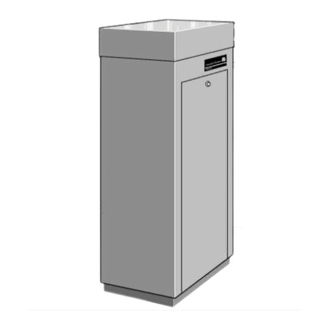
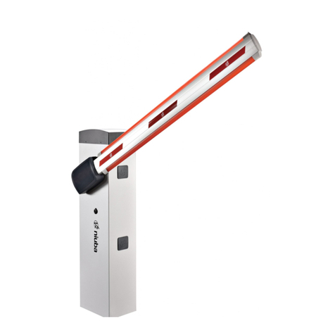
Tiso Optimus RB392 Series Installation guide


2
CONTENT
1. Description of the Boom Barrier control units and electric parts ......................................................................3
1.1. Purpose and operation of Boom Barrier control units and electric parts.......................................................3
1.2. Description of the versatile controller PCB349..............................................................................................4
1.2.1 Description of the PCB349 controller components......................................................................................5
1.2.2 Description of controller contacts ................................................................................................................6
2. Connection of Boom Barrier and putting it into operation...............................................................................13
2.1. Connection of Boom Barrier and putting it into operation............................................................................13
2.2. Troubleshooting...........................................................................................................................................15
3.1. Wire remote control panel RB111 ...............................................................................................................16
3.2. Boom Barrier wireless control......................................................................................................................17
3.3. Protective induction loops............................................................................................................................18
4. Road Blocker operator's guide .......................................................................................................................21
5. Boom Barrier electric part maintenance instruction........................................................................................23
6. List of replacement components in case of failure .........................................................................................24
Annex 1. Boom Barrier Connection Diagram .....................................................................................................25
Annex 2. Wiring Diagram of Boom Barrier with additional devices....................................................................26
The electrical operation and maintenance manual of boom barriers RB391, RB392, RB395, RB396
is intended to be used together with the Installation and Operation Manual. Part I Automatic boom
barrier "Optimus" RB396 and RB392 series.

3
1. Description of the Boom Barrier control units and electric parts
The Boom Barrier shall be installed and connected to power supply network and other devices,
maintained only by certified professionals carefully observing electrical and mechanical safety
regulations.
This Manual must be scrutinized prior to the Boom Barrier installation, connection, putting into
operation and maintenance!
1.1. Purpose and operation of Boom Barrier control units and electric parts
The Boom Barrier electric control unit is a controller with additional electric parts and is designed to
control the Boom Barrier.
The control unit is assembled in a plastic box and is located inside the Boom Barrier rack. Power supply
and control signals are connected to the control unit.
All control units are assembled based on the versatile controllers PCB349.
The controller PCB349 is a versatile device designed to control road blockers. In general one control unit
can control two independent homogeneous road blockers fully independently. But in boom barriers only the first
control channel is used. The second channel is not used and nothing is connected to the relevant terminals.
Fig.1 - Boom Barrier Control Unit

4
1.2. Description of the versatile controller PCB349
Fig. 2 - Illustration of controller PCB349 with identification of its components, inputs and outputs

5
1.2.1 Description of the PCB349 controller components
The controller PCB349 controls operation of devices by analyzing signals from potential inputs, angular
position sensors and wire pushbutton control panel connected via interface RS485 and sets potential outputs
depending on the Road Blocker status. Table 1 contains description of the PCB349 controller components
Item
Component
Purpose
1
Terminal block X1 PS
Power Supply 230V AC–Terminal block for connection of controller
supply voltage 230VAC
2
Terminal block X2 M1
Motor 1 –Terminal block for connection of the Road Blocker1 built-in
hydraulic unit motor
3
Terminal block X3 M2
Motor 2 –Terminal block for connection of the Road Blocker2
built-in hydraulic unit motor
4
Fuse F1
Fuse 1 –Fuse 6A 250VAC of the Road Blocker1 mini hydraulic unit
motor
5
Fuse F2
Fuse 2 –Fuse 6A 250VAC of the Road Blocker2 mini hydraulic unit
motor
6
Terminal block С1
Capacitor 1 –Terminal block for connection of the Road Blocker1
mini hydraulic unit capacitor С1
7
Terminal block С2
Capacitor 2 –Terminal block for connection of the Road Blocker2
mini hydraulic unit capacitor С2
8
Terminal block X5 INP1
Inputs 1 –Terminal block for connection of the Road Blocker 1
control inputs, sensors and additional devices
9
Terminal block X6 OUT1
Outputs 1 –Terminal block for connection of the Road Blocker 1
actuating devices and additional devices
10
Terminal block X7 INP2
Inputs 2 –Terminal block for connection of the Road Blocker2
control inputs, sensors and additional devices
11
Terminal block X8 OUT2
Outputs 2 –Terminal block for connection of the Road Blocker 2
actuating devices and additional devices
12
Terminal block X9 RS485
Interface RS485 –Terminal block for connection of the Road
Blocker 1 and 2 remote control panel and angular position sensors
13
Terminal block X4 230V
TO PSU
230V to Power Supply Unit –Terminal block for connection of the
power supply unit voltage 230VAC
14
Terminal block
X10. 12V from PSU
12V DC from Power Supply Unit –Terminal block for connection of
the power supply unit voltage 12VDC
15
Switch SW1- SW8
Switch 1-8 –Switch of the control unit mode and configuration
parameter setting
16
Displays LED1-LED8
Displays of mode and configuration parameters
17
Displays LED18-LED26
Displays of the Road Blocker1 input INP1 status
18
Displays LED9-LED17
Displays of the Road Blocker2 input INP2 status
19
Displays LED33-LED38
Displays of the Road Blocker1 output OUT1 status
20
Displays LED27-LED32
Displays of the Road Blocker2 output OUT2 status

6
1.2.2 Description of controller contacts
Table 2 contains description of terminal block X1 PS –Power Supply 230V AC.
Power voltage 230VAC from switch B6. Circuit Breaker to be connected to terminal block X1 PS
Power Supply 230V AC.
Item
Terminal name
Purpose
3
230V AC IN PE
Input for connection of protective earthing PE of power network voltage
230VAC
4
230V AC IN N
Input for connection of neutral N of power network voltage 230VAC
5
230V AC IN L
Input for connection of phase L of power network voltage 230VAC
Table 3 contains description of terminal block X2 M1 –Motor 1
1-phase MINI hydraulic unit motor of the Road Blocker1 to be connected to terminal block X2 M1.
Item
Terminal name
Purpose
6
MOTOR 1 UP L
Output for connection of phase L of the Road Blocker1 raisingmotor
7
MOTOR 1 DOWN L
Output for connection of phase L of the Road Blocker1 lowering motor
8
MOTOR 1 L
Not used
9
MOTOR 1 N
Output for connection of neutral N of the Road Blocker1 motor
10
MOTOR 1 PE
Output for connection of protective earthing PE of the Road Blocker1
motor
When the road blockers are used with peripheral hydraulic unit or built-in with 3-phase power
supply, then outputs 6. MOTOR 1 UP L and 7. MOTOR 1 DOWN L are used to control additional
contactors or solenoid valves.
Table 4 contains description of terminal block X3 M2 –Motor 2
1-phase MINI hydraulic unit motor of the Road Blocker2 to be connected to terminal block X3M2 –
Motor2.
Item
Terminal name
Purpose
11
MOTOR 2 UP L
Output for connection of phase L of the Road Blocker2 raising motor
12
MOTOR 2 DOWN L
Output for connection of phase Lоf the Road Blocker2 lowering motor
13
MOTOR 2 L
Not used
14
MOTOR 2 N
Output for connection of neutral N of the Road Blocker2 motor
15
MOTOR 2 PE
Output for connection of protective earthing PE of the Road Blocker2
motor
When the road blockers are used with peripheral hydraulic unit or built-in with 3-phase power supply,
then outputs 11. MOTOR 2 UP L and 12. MOTOR 2 DOWN L are used to control additional
contactors or solenoid valves.

7
Table 5 contains description of terminal block X5. INP1
The Road Blocker1 control inputs, sensors and additional devices to be connected to terminal
block X5. INP1 –Inputs 1.
Item
Terminal name
Purpose
16
INP "UP" 1
The Road Blocker raising input. The road blocker will start raising
when it is activated.
17
INP "STOP" 1
The Road Blocker stop input. The Road Blocker will stop when it is
activated.
When the input is active, then the Road Blocker will be in stop
status. It has the highest priority and is used for connection of "Stop"
button B5. Remote Emergency Push Button "Stop"
18
INP "DOWN" 1
The road blocker lowering input. The Road Blocker will start lowering
when it is activated.
19
INP "FORSE" 1
The road blocker rapid raising input. The road blocker will start rising
with maximum speed when it is activated. It is used only in the road
blockers with accumulator.
20
GND
Common wire GND.
21
INP "SENSOR TOP
1"
Input for connection of UP position sensor. The Road Blocker will
stop when it is activated during raising. When the input is active, then it
will not respond to raising command.
22
INP "SENSOR BOT
1"
Input for connection of DOWN position sensor. The Road Blocker
will stop when it is activated during lowering. When the input is active,
then it will not respond to lowering command.
23
INP "SENSOR 3" 1
Input for connection of pressure valve.
It is used only in the road blockers with accumulator.
24
GND
Common wire GND.
25
INP "SAFETY 1" 1
Protective entry sensor input. Induction loop controller or entry safety
photocell to be connected to the input.
It is designed to prevent the Road Blocker raising, when a vehicle is
found on it. The Road Block er will stop or will start lowering when
it is activated during raising. Response type is selected by the switch
SW1.7
26
INP "SAFETY 2" 1
Protective exit sensor input. Induction loop controller or exit safety
photocell to be connected to the input.
It is designed to prevent the Road Blocker raising, when a vehicle is
found on it. The Road Blocker will stop or will start lowering when it is
activated during raising. Response type is selected by the switch SW1.7
27
GND
Common wire GND.
All inputs INP1 include similar interface and are compatible with outputs of "dry contact" or "open
collector".
The input is active when it is connected to one of common wires GND.
It is inactive when it is not connected to GND
Status of inputs INP1 is indicated by displays LED18-LED26 located next to them.

8
Table 6 contains description of terminal block X7. INP2
The Road Blocker2 control inputs, sensors and additional devices to be connected to terminal block
X7. INP2 –Inputs 2.
Item
Terminal name
Purpose
46
INP "UP" 2
The Road Blocker raising input. The Road Blocker will start raising
when it is activated.
47
INP "STOP" 2
The Road Blocker stop input. The Road Blocker will stop when
activated. When the input is active, then the Road Blocker will be in
stop status. It has the highest priority and is used for connection of
"Stop" button B5. Remote Emergency Push Button "Stop"
48
INP "DOWN" 2
The Road Blocker lowering input. The Road Blocker will start lowering
when it is activated.
49
INP "FORSE" 2
The Road Blocker rapid raising input. The Road Blocker will start
raising with maximum speed when activated.
It is used only in the road blockers with accumulator.
50
GND
Common wire GND.
51
INP "SENSOR TOP 2"
Input for connection of UP position sensor. The Road Blocker will stop
when it is activated during raising. When the input is active, then it will
not respond to raising command. .
52
INP "SENSOR BOT 2"
Input for connection of DOWN position sensor. The Road Blocker will
stop when it is activated during lowering. When the input is active,
then it will not respond to lowering command.
53
INP "SENSOR 3" 2
Input for connection of pressure valve.
It is used only in the road blockers with accumulator.
54
GND
Common wire GND.
55
INP "SAFETY 1" 2
Protective entry sensor input. Induction loop controller or entry safety
Photocell to be connected to the input.
It is designed to prevent the road blocker raising, when a vehicle is
found on it.
The road blocker will stop or will start lowering when it is activated
during raising. Response type is selected by the switch SW1.7.
56
INP "SAFETY 2" 2
Protective exit sensor input. Induction loop controller or exit safety
photocell to be connected to the input.
It is designed to prevent the Road Blocker raising, when a vehicle is
found on it. The Road Blocker will stop or will start lowering when it is
activated during raising. Response type is selected by the switch
SW1.7
57
GND
Common wire GND.
All inputs INP2 include similar interface and are compatible with outputs of "dry contact" or
"open collector" type.
The input is active when it is connected to one of common wires GND.
It is inactive when it is not connected to GND
Status of inputs INP2 is indicated by displays LED9-LED17 located next to them.
Connection to the terminal block INP2 is performed via the additional intermediate terminal block B3-
TX2. Connection blocks INP2 Wago 260.

9
Table 7 contains description of terminal block X6. OUT1
The Road Blocker1 actuating and additional devices to be connected to terminal block X6. OUT1 –
Outputs 1.
Item
Terminal name
Purpose
28
+12VDC
+12VDC power voltage output for energization of actuating and
additional devices.
29
INDICATION RED 1
Output for connection of the Road Blocker1 red display module.
30
INDICATION GREEN 1
Output for connection of the Road Blocker1 green display module.
31
SOUND 1
Output for connection of the Road Blocker1 siren.
32
+12VDC
+12VDC power voltage output for energization of actuating and
additional devices.
33
TRAF. L. TOP OUT 1
The Road Blocker1 UP position output.
It is active when the Road Blocker1 is in UP position.
It is inactive when the Road Blocker1 is not in UP
position. It can be used by access control system.
34
TRAF. L. BOT OUT 1
The Road Blocker1 DOWN position output.
It is active when the Road Blocker1 is in DOWN position.
It is inactive when the Road Blocker1 is not in DOWN position.
It can be used by access control system or for traffic light relay control.
35
OUT 1
The Road Blocker1 accumulator valve control output.
It is used only in the road blockers with accumulator.
36
+ INDICATION LED 1
Output for connection of the Road Blocker 1 additional LED 1 display
module anode "+"
37
- INDICATION LED 1
Output for connection of the Road Blocker1 additional LED 1 display
module cathode "-".
All outputs but INDICATION LED include similar interface of "open collector" type.
The load capacity of outputs 29. INDICATION RED 1, 30. INDICATION GREEN 1, 31. SOUND 1 is
1,5А.
The load capacity of outputs 33. TRAF. L. TOP OUT 1, 34. TRAF. L. BOT OUT 1, 35. SOUND 1 is 0,2
А.
The output status is indicated by displays LED18-LED26 located next to them.
Table 8 contains description of terminal block X8. OUT2
The Road Blocker 2 actuating and additional devices to be connected to terminal block X8.
OUT2 –Outputs 2.
Item
Terminal name
Purpose
58
+12VDC
+12VDC power voltage output for energization of actuating and
additional devices.
59
INDICATION RED 2
Output for connection of the Road Blocker2 red display module.
60
INDICATION GREEN 2
Output for connection of the Road Blocker2 green display module.
61
SOUND 2
Output for connection of the Road Blocker2 siren.
62
+12VDC
+12VDC power voltage output for energization of actuating and
additional devices.
63
TRAF. L. TOP OUT 2
The Road Blocker 2 UP position output.
It is active when the Road Blocker2 is in UP position.
It is inactive when the Road Blocker1 is not in UP position. It can be used
by access control system.

10
Continuation table 8
1
2
3
64
TRAF. L. BOT OUT 2
The Road Blocker2 DOWN position output.
It is active when the Road Blocker1 is in DOWN position.
It is inactive when the Road Blocker1 is not in DOWN position.
It can be used by access control system or for traffic light relay control.
65
OUT 2
The Road Blocker 2 accumulator valve control output. It is used only in
the road blockers with accumulator.
66
+ INDICATION LED 2
Output for connection of the Road Blocker 2 additional LED 1 display
module anode "+".
67
- INDICATION LED 2
Output for connection of the Road Blocker 2 additional LED 1 display
module cathode"-".
All outputs but INDICATION LED include similar interface of "open collector" type.
The load capacity of outputs 59.INDICATION RED 2, 60.INDICATION GREEN 2, 61.SOUND 2 is 1,5 А.
The load capacity of outputs 63.TRAF.L.TOP OUT 2, 64. TRAF.L.BOT OUT 2, 65. SOUND 2 is 0,2 А.
The output status is indicated by displays LED27-LED32 located next to them.
Connection to terminal blocks is performed via the additional intermediate terminal block B3-TX3.
Connection block OUT2 Wago 260.
Table 9 contains description of terminal block X9. RS485
The Road blocker 1 and 2 remote control panel RB111 and angular position sensors DI-601 to be
connected to terminal block X9. RS485 –Interface RS485.
Item
Terminal name
Purpose
38
+12VDC
+12VDC power voltage of remote control panel DI-601
39
RS485 A1
Signal RS485 A of angular position sensors DI-601
40
RS485 B1
Signal RS485 B of angular position sensors DI-601
41
GND
Common wire GND of angular position sensors DI-601
42
+12VDC
+12VDC power voltage of remote control panel RB111
43
RS485 A2
Signal RS485 A of remote control panel RB111
44
RS485 B2
Signal RS485 B of remote control panel RB111
45
GND
Common wire GND of remote control panel RB111
The remote control panel RB111 can be located at a distance of up to 500 meters from
control unit. If distance from the remote control panel RB111 to control unit is less than 50 m, then
any cable with wire section 4х0,22 can be used for connection.
When distance is more than 50 m, then cable UTP or FTP 4x2x0,51 to be used. In this case two
wires of one twisted pair to be used for signals RS485 A and RS485 B.
When two road blockers are used with one control unit, then the Road Blocker 1 and 2 angular
position sensors DI-601 to be connected to terminals 42-45 of terminal block X9. RS485 in parallel.
Addresses of the Road Blocker1 and 2 angular position sensors DI-601 are different - 1 and 2
respectively.
Sensor address is indicated on inspection box of Road Blocker electrical connections and on the
sensor DI-601 itself.
The angular position sensors DI-601 are used only in the Road Blockers of “High Security Road
Blocker”, “Cyclope”, “Speedbump” types.
In the Road Blockers of “Bollard”, “Tire Killer”, “Boom Barrier” types magnetic limit switches are used as
end position sensors.

11
Table 10 contains description of switch SW1
The switch SW1- SW8 –Switch 1-8 is designed for selection of operation modes and setting of
configuration parameters.
Item
Switch name
Purpose
1
SW1
Activation of the boom lift function if it did not reach the lower position during
lowering
2
SW2
Enabling the boom slow function at the end of the movement
3
SW3
Duration of deceleration when lifting 1 or 2 seconds
4
SW4
Deceleration time when lowering 1 or 2 seconds
5
SW5
If the switch is in the OFF position
TRAFFIC_LIGHT_TOP_OUT_1 and TRAFFIC_LIGHT_TOP_OUT_2 - show that
the road blocker in the TOP position.
If the switch is in the ON position
TRAFFIC_LIGHT_TOP_OUT_1 and TRAFFIC_LIGHT_TOP_OUT_2 - show that
the road blocker is not in the BOTOM position.
Thus to TRAFFIC_LIGHT_BOT_OUT it is possible to connect a green traffic light
lamp, and to TRAFFIC_LIGHT_TOP_OUT - to red.
6
SW6
Not applicable
7
SW7
Type of response on signals of inputs of protective sensors –induction
loops or safety photocells 25, 26, 55, 56 "INP Safety".
When the switch is OFF, then road blocker will be stopped when signal is
coming on INP Safety.
When the switch is ON, then road blocker will be lowering when signal is
coming on INP Safety.
8
SW8
Not applicable
Table 11 contains description of indicators LED1-LED8
The indicators LED1-LED8 are designed to display the Road blocker operation modes and
configuration parameters.
Item
Indicator name
Purpose
1
LED1
It is lit when there is no contact with wire remote control panel RB111.
It is not lit when wire remote control panel is connected and operates properly.
2
LED2
It is lit when there is no contact between angular position sensors DI-601 and
address 1 (road blocker 1).
It is not lit when DI-601 of the Road blocker 1 is connected and operates
properly.
3
LED3
It is lit when there is no contact between angular position sensors DI-601 and
address 2 (road blocker 2).
It is not lit when DI-601 of the Road blocker 2 is connected and operates
properly.
4
LED4
Not applicable
5
LED5
Not applicable
6
LED6
Not applicable
7
LED7
Displays position of the switch SW7
8
LED8
Not applicable

12
The PCB349 controller has two TIME1 (left) and TIME2 (right) regulators.
The TIME1 regulator is used to adjust the timeout for raising and lowering. If the road blocker limit
switches is not connected, - the road blocker will be started only for the time duration from 3to 17 seconds,
selected by the TIME1, after each raise or lower command, and will stop after this timeout has been completed.
The timeout of raising and lowering increases when the regulators is rotate clockwise and decreases it
rotate counterclockwise. The minimum value is 3seconds, the maximum value is 17 seconds.
The TIME2 regulators is for future use.
Fig.3 - Raising and lowering timeout TIME1 regulator.
Fig. 4- Rising and lowering timeout regulator TIME1 in position 3sec, 8sec, 17sec.

13
2. Connection of Boom Barrier and putting it into operation
In further description of Boom Barrier connection to control unit and other devices, connection and wiring
diagrams the maximum configuration of accessories and options are specified.
When in particular separate configuration some components are not used, then they just are not
connected or not taken into account.
The additional options are as follows:
-Heating with heating thermostat. It is used in case of frost.
-Cooling fan with cooling thermostat. It is used in case of hot at the installation site.
-Audible alarm. It is an additional option to be installed on the Boom Barrier.
-Radio controller of wireless remote control. It is an additional option to be used for road
blocker wireless control from remote control panels (remote control pendants).
-Induction loop controllers. It is an additional option to be used for connection of induction
loops to prevent the Boom Barrier raising when a vehicle is under boom.
All optional device of control units and Boom Barrier which can be unused and are options are
marked with "*" on diagrams.
Limit switches are used as the Boom Barriers’ up and down position sensors.
2.1. Connection of Boom Barrier and putting them into operation
After the Boom Barrier installation the control unit is connected 230VAC power supply network via
safety switch B6. Circuit Breaker placed in convenient location.
The differential breaker 10А 30мА to be used as switch (overload and leakage protection), such as ABB
DS951 C10-30MA/AC.
Control signals (for example, access control system), remote control panel B4-А1. Remote Control Unit
PCB111 (optional), emergency "Stop" button B5-А1, Remote Emergency Push Button "Stop" ASCO XAL-
J174 and actuating devices, for example, traffic lights, external siren are connected to control unit.
General connection diagram of the Boom Barrier and additional devices is shown in Annex 1.
Wiring diagram of the Boom Barrier with control unit and additional devices is shown in Annex 2.
The switch B6-K1. Circuit Breaker, the emergency stop button B5-А1. Remote Emergency Push
Button "Stop" to be connected to the control unit. The wire remote control panel B4-А1. Remote Control
Unit RB111
1
and other additional devices, such as traffic lights or access control system, can be
connected.
The emergency stop button B5-А1. Remote Emergency Push Button "Stop" and remote control panel
B4-А1. Remote Control Unit RB111* are installed at the road blocker operator workstation.
The supply voltage 230VAC to be connected and the switch B6. Circuit Breaker to be ON after
completion of the Boom Barrier installation, boom balancing and all connections.
Trial raising and lowering of Boom Barrier to be initiated after completion of all connections and
energization. Proper operation to be controlled. If the Boom Barrier operation is improper, then the cause to be
found and the problem to be remedied using Table 12.
The Boom Barrier has an automatic boom raising function, when it does not reach the down position
during lowering (comes up against obstacle, down position sensor is not actuated).
The automatic boom raising function during coming up against obstacle is activated with the switch SW1.
The Boom Barrier has a boom deceleration function upon completion of opening or closing.
The deceleration function is activated with the switch SW2.
The SW3 switch position determines the deceleration duration during raising. When it is ON - 1 second,
when it is OFF- 2 seconds.
The SW4 switch position determines the deceleration duration during lowering. When it is ON - 1 second,
when it is OFF- 2 seconds.
1
The differential breaker 10А 30мА to be used as switch (overload and leakage protection), such as ABB DS951 C10-
30MA/AC.

14
The Boom Barrier stop or deceleration points during raising or lowering are determined by the of the
position sensors position –limit switches and magnets.
If appropriate, end position sensors to be adjusted according to the diagram shown in Fig. 5.
Fig.5 - Adjustment of the Boom Barrier position sensors - limits switches and magnets.

15
2.2. Troubleshooting
Table 12 –Troubleshooting
Item
Malfunction
Possible cause
Action
1
Boom Barrier is
neither raised nor
sunk when raising or
lowering command
is issued
Boom Barrier motor B2-А1.
Motor is not connected or
connected improperly to control
unit
Connections to be verified according to
description and diagrams in Annex 1
and Annex 2 as well as errors to be
eliminated and connection to be made
properly
Boom Barrier end position
sensors Sensor TOP or Sensor
BOT are connected improperly
Connections of, LED displays LED22
(TOP1), LED23 (BOT1) to be checked
according to diagrams in Annex 1 and
Annex 2 and Table 12 as well as errors
to be eliminated and connection to be
made properly
2
Continuous operation
of motor after
reaching UP and
DOWN position by
Boom Barrier
End position sensors Sensor
TOP or Sensor BOT are not
connected, connected improperly
or unadjusted
Connections of, LED displays LED22
(TOP1), LED23 (BOT1) to be checked
according to Annex 1 and Annex 2 as
well as errors to be eliminated and
connection to be made properly
3
Boom Barrier audio
or visual alarm is
inoperative
Boom Barrier audio or visual
alarm is not connected or
connected improperly
Connections to be checked according
to diagrams in Annex 1 and Annex 2
as well as errors to be eliminated and
connection to be made properly
Fig 6 - Boom Barrier Control Unit
Fig. 7 -The Boom Barrier control unit with remote
control unit RB111, emergency stop button and ON/OFF
switch

16
3.1. Wire remote control panel RB111
Fig. 8 - Front face of control panel RB111
The wire remote control unit RB111 can be used for the road blocker control.
In general the control panel can control two independent devices connected to one control unit.
Buttons "1 UP", "1 DOWN", "1 STOP" are used for the road blocker 1 control.
Buttons "2 UP", "2 DOWN", "2 STOP" are used for the road blocker 2 control.
Road blocker is raised when "UP" button is pushed. The lamp near "UP" button will be blinking
during raising. When road blocker reaches the uppermost position and stops, then the lamp near
"UP" button will be steadily lit - UP position display.
Road blocker is sunk when "DOWN" button is pushed. The lamp near "DOWN" button will be
blinking during lowering. When Road blocker reaches the lowermost position and stops, then the
lamp near "DOWN" button will be steadily lit - DOWN position display.
Road blocker is stopped when "STOP" button is pushed during raising or lowering.
The remote control panel RB111 is equipped with built-in road blocker movement alarm and produces
harmonic signals during road blocker raising and lowering.
The indicator "Communication" displays availability or lack of connection with control unit.
If it is green, then connection is available. If it is red, then connection is lack. When there is no
connection, then remote control panel produces pulsed sounds.
The indicator "Trouble" displays availability or lack of failure of remote control panel. If it is green, then
remote control panel is operating properly. If it is red, then remote control panel is operating improperly.

17
3.2. Boom Barrier wireless control
The Boom Barrier control unit may include additional option –Boom Barrier wireless control by remote
control pendants.
In this case control unit includes B3-A3. Wireless Remote Controller Satel RE-2K * and scope of
delivery includes some remote control pendants Satel T-2.
Maximum allowable distance from remote control pendant to control unit is 25 m.
Fig. 9 - Wireless controller Satel RE-2K and remote control pendants Satel T-2.
Green "UP" button of remote control pendant Satel T-2 to be pushed to raise the road blocker.
Red "DOWN" button of remote control pendant Satel T-2 to be pushed to sink the road blocker.
To add new remote control pendants Satel T-2 in storage of wireless controller Satel RE-2K it is
necessary to open top lid and:
1. Programming button "PROGRAM" to be pushed –LED of wireless controller Satel RE-2K
starts blinking green.
2. Any button of remote control pendant to be pushed –LED starts blinking red.
3. Button of remote control pendant to be repushed –LED is lit green.
Remote control pendant is added.
More details on wireless controller Satel RE-2K can be found on the manufacturer's website by
reference: https://www.satel.pl/en/produktid/483 .

18
3.3. Protective induction loops
The Boom Barrier control unit may include additional option –protective induction loops.
One or two induction loops are installed in roadbed next to the Boom Barriers, are connected to
control unit and are used to prevent the Boom Barrier raising when a vehicle is on induction loop.
Fig.10 - Example of induction loop layout next to the road blocker
If Boom Barrier has induction loop option, then control unit contains one or two controllers of induction
loops B3-A4. Safety Loop Detector A EMX ULTRADIN * and B3-A4. Safety Loop Detector A EMX
ULTRADIN *.
The scope may also include some cables SIF1.0 for preparation of induction loops.
The maximum allowable distance from induction loop to control unit is 20 m.
Induction loop responds to vehicle metal and at its location there should not be metal in road
surface. Minimum distance from induction loop to metal parts is 500 mm.
A trench of 50-70 mm depth and 15-25 mm width according to induction loop size is made for
installation of induction loop in road surface. A trench is also made from the edge of induction loop to
control unit.
Induction loop is 3-4 turns of cable SIF1.0 to be installed in trench the ends of which are twisted
between them and connected to induction loop controller of control unit. Cable SIF1.0 can be laid in
plastic corrugated tube or plastic pipe. After induction loop is laid in pipe it is filled with sand and covered with
cement or asphalt grout.

19
Table 13 contains recommended induction loop size, number of turns and vehicle over induction loop
detection height
Length
Width
Turns
Detection Height Feet
2 (0.61m)
2 (0.61m)
5
1.6 (0.488m)
2 (0.61m)
4 (1.22m)
4
1.6 (0.488m)
2 (0.61m)
6 (1.83m)
4
1.6 (0.488m)
2 (0.61m)
8 (2.44m)
3
1.6 (0.488m)
2 (0.61m)
10 (3.05m)
3
1.6 (0.488m)
2 (0.61m)
12 (3.66m)
3
1.6 (0.488m)
2 (0.61m)
14 (4.27m)
3
1.6 (0.488m)
2 (0.61m)
16 (4.88m)
3
1.6 (0.488m)
2 (0.61m)
18 (5.49m)
3
1.6 (0.488m)
2 (0.61m)
20 (6.10m)
3
1.6 (0.488m)
4 (1.22m)
4 (1.22m)
4
3.2 (0.975m)
4 (1.22m)
6 (1.83m)
4
3.2 (0.975m)
4 (1.22m)
8 (2.44m)
3
3.2 (0.975m)
4 (1.22m)
10 (3.05m)
3
3.2 (0.975m)
4 (1.22m)
12 (3.66m)
3
3.2 (0.975m)
4 (1.22m)
14 (4.27m)
3
3.2 (0.975m)
4 (1.22m)
16 (4.88m)
3
3.2 (0.975m)
4 (1.22m)
18 (5.49m)
3
3.2 (0.975m)
4 (1.22m)
20 (6.10m)
3
3.2 (0.975m)
4 (1.22m)
22 (6.71m)
3
3.2 (0.975m)
4 (1.22m)
24 (7.32m)
3
3.2 (0.975m)
4 (1.22m)
26 (7.93m)
3
3.2 (0.975m)
4 (1.22m)
28 (8.54m)
3
3.2 (0.975m)
4 (1.22m)
30 (9.14m)
2
3.2 (0.975m)
4 (1.22m)
32 (9.75m)
2
3.2 (0.975m)
4 (1.22m)
33 (10.06m)
2
3.2 (0.975m)
4 (1.22m)
34 (10.36m)
2
3.2 (0.975m)
4 (1.22m)
36 (10.97m)
2
3.2 (0.975m)
4 (1.22m)
38 (11.58m)
2
3.2 (0.975m)
4 (1.22m)
40 (12.20m)
2
3.2 (0.975m)
6 (1.83m)
6 (1.83m)
4
4.8 (1.463m)
6 (1.83m)
8 (2.44m)
3
4.8 (1.463m)
6 (1.83m)
10 (3.05m)
3
4.8 (1.463m)
6 (1.83m)
12 (3.66m)
3
4.8 (1.463m)
6 (1.83m)
14 (4.27m)
3
4.8 (1.463m)
6 (1.83m)
16 (4.88m)
3
4.8 (1.463m)
6 (1.83m)
18 (5.49m)
3
4.8 (1.463m)
6 (1.83m)
20 (6.10m)
2
4.8 (1.463m)
6 (1.83m)
22 (6.71m)
2
4.8 (1.463m)
6 (1.83m)
24 (7.32m)
2
4.8 (1.463m)
6 (1.83m)
26 (7.93m)
2
4.8 (1.463m)
6 (1.83m)
28 (8.54m)
2
4.8 (1.463m)
6 (1.83m)
30 (9.14m)
2
4.8 (1.463m)
6 (1.83m)
32 (9.75m)
2
4.8 (1.463m)
6 (1.83m)
33 (10.06m)
2
4.8 (1.463m)
6 (1.83m)
34 (10.36m)
2
4.8 (1.463m)
6 (1.83m)
36 (10.97m)
2
4.8 (1.463m)
6 (1.83m)
38 (11.58m)
2
4.8 (1.463m)

20
6 (1.83m)
40 (12.20m)
2
4.8 (1.463m)
8 (2.44m)
4 (1.22m)
4
3.2 (0.975m)
8 (2.44m)
6 (1.83m)
4
4.8 (1.463m)
8 (2.44m)
8 (2.44m)
3
5.6 (1.71m)
8 (2.44m)
10 (3.05m)
3
5.6 (1.71m)
8 (2.44m)
12 (3.66m)
3
5.6 (1.71m)
8 (2.44m)
14 (4.27m)
3
5.6 (1.71m)
8 (2.44m)
16 (4.88m)
3
5.6 (1.71m)
8 (2.44m)
18 (5.49m)
2
5.6 (1.71m)
8 (2.44m)
20 (6.10m)
2
5.6 (1.71m)
8 (2.44m)
22 (6.71m)
2
5.6 (1.71m)
8 (2.44m)
24 (7.32m)
2
5.6 (1.71m)
8 (2.44m)
26 (7.93m)
2
5.6 (1.71m)
8 (2.44m)
28 (8.54m)
2
5.6 (1.71m)
8 (2.44m)
30 (9.14m)
2
5.6 (1.71m)
8 (2.44m)
32 (9.75m)
2
5.6 (1.71m)
8 (2.44m)
33 (10.06m)
2
5.6 (1.71m)
8 (2.44m)
34 (10.36m)
2
5.6 (1.71m)
8 (2.44m)
36 (10.97m)
2
5.6 (1.71m)
8 (2.44m)
38 (11.58m)
2
5.6 (1.71m)
8 (2.44m)
40 (12.20m)
2
5.6 (1.71m)
Two twisted ends of cable SIF1.0 of each induction loop to be connected to terminals "LOOP" and
"LOOP" of Safety Loop Detector EMX ULTRADIN induction loop controller of control unit.
Fig.11 - Diagram of connection of induction loop to Safety Loop Detector EMX ULTRADIN induction
loop controller of control unit.
After induction loop is installed, connected to controller and energized "Calibration" button to be
pushed and 10 sec to be waited in order controller to be calibrated.
Position of adjuster "Activation level regulation" determines at which level of vehicle presence
detector is activated. Normally position 4-5 is set.
Indicator "Vehicle presence level" displays vehicle presence level.
More details on induction loop controller EMX ULTRADIN can be found on the manufacturer's
website by reference: http://www.emxinc.com/vehicle_loop_detector_ultra-din.html
This manual suits for next models
1
Table of contents
Other Tiso Automatic Barrier manuals
