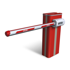
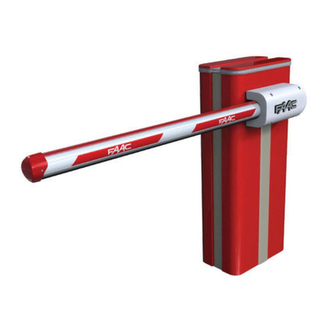
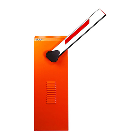
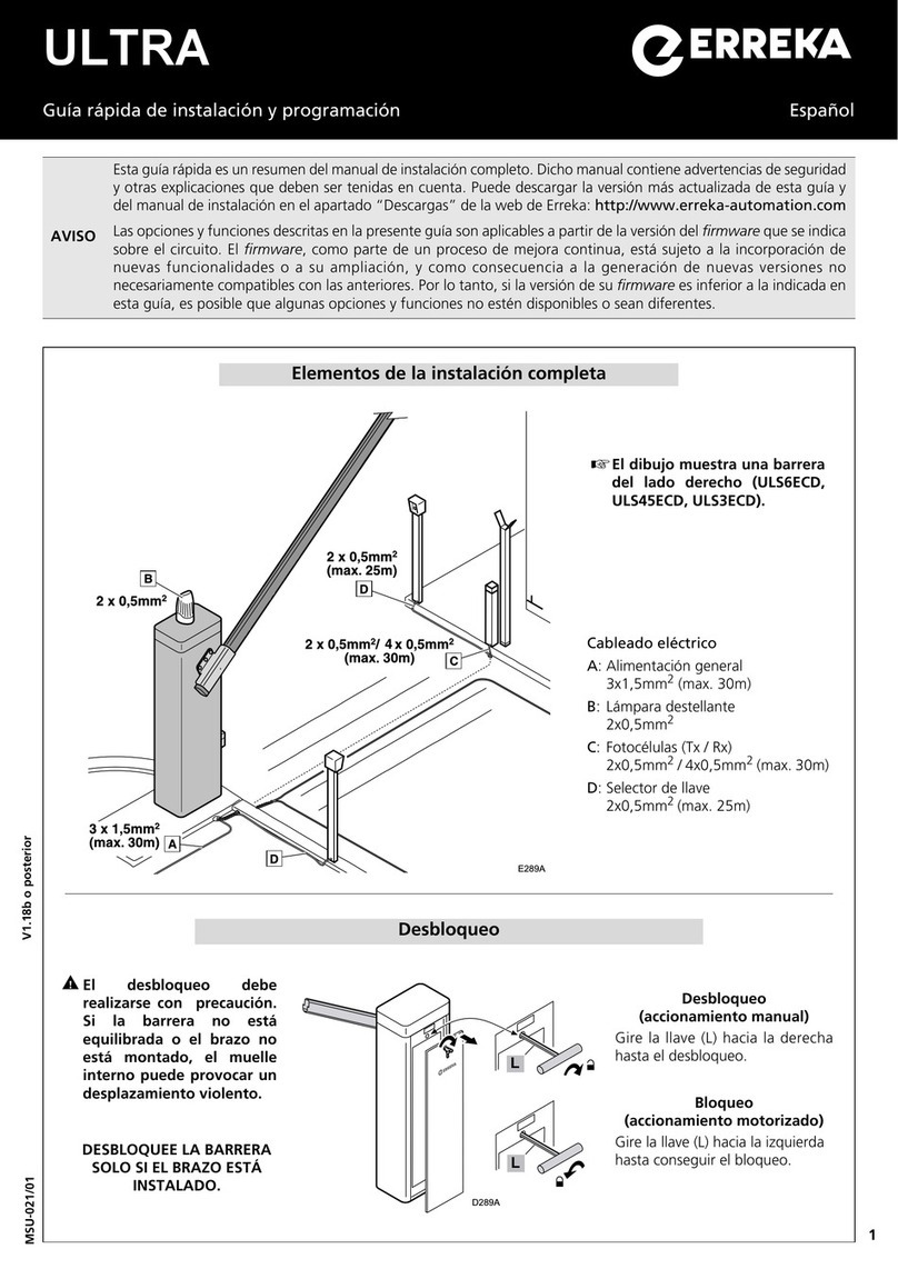
FAAC B680H User manual

B680H
Translation of the original instructions

FAAC S.p.A. Soc. Unipersonale
Via Calari, 10 - 40069 Zola Predosa BOLOGNA - ITALY
Tel. +39 051 61724 - Fax +39 051 09 57 820
www.faac.it - www.faacgroup.com
© Copyright FAAC S.p.A. dal 2019. Tutti i diritti riservati.
Nessuna parte di questo manuale può essere riprodotta, archiviata, distribuita a terzi
né altrimenti copiata, in qualsiasi formato e con qualsiasi mezzo, sia esso elettronico,
meccanico o tramite fotocopia, senza il preventivo consenso scritto di FAAC S.p.A.
Tutti i nomi e i marchi citati sono di proprietà dei rispettivi fabbricanti.
I clienti possono effettuare copie per esclusivo utilizzo proprio.
Questo manuale è stato pubblicato nel 2019.
© Copyright FAAC S.p.A. from 2019. All rights reserved.
No part of this manual may be reproduced, archived, distributed to third parties nor
copied in any other way, in any format and with any means, be it electronic, mechanical
or by photocopying, without prior written authorisation by FAAC S.p.A.
All names and trademarks mentioned are the property of their respective manu-
facturers.
Customers may make copies exclusively for their own use.
This manual was published in 2019.
© Copyright FAAC S.p.A. depuis 2019. Tous droits réservés.
Aucune partie de ce manuel ne peut être reproduite, archivée ou distribuée à des tiers
ni copiée, sous tout format et avec tout moyen, qu’il soit électronique, mécanique ou
par photocopie, sans le consentement écrit préalable de FAAC S.p.A.
Tous les noms et les marques cités sont la propriété de leurs fabricants respectifs.
Les clients peuvent faire des copies pour leur usage exclusif.
Ce manuel a été publié en 2019.
© Copyright FAAC S.p.A. ab dem 2019. Alle Rechte vorbehalten.
Kein Teil dieses Handbuchs darf reproduziert, gespeichert, an Dritte weitergegeben
oder sonst auf eine beliebige Art in einem beliebigen Format und mit beliebigen
Mitteln kopiert werden, weder mit elektronischen, noch mechanischen oder durch
Fotokopieren, ohne die Genehmigung von FAAC S.p.A.
Alle erwähnten Namen und Marken sind Eigentum der jeweiligen Hersteller.
Die Kunden dürfen nur für den Eigengebrauch Kopien anfertigen.
Dieses Handbuch wurde 2019 veröffentlicht.
© Copyright FAAC S.p.A. del 2019. Todos los derechos están reservados.
No puede reproducirse, archivarse, distribuirse a terceros ni copiarse de ningún modo,
ninguna parte de este manual, con medios mecánicos o mediante fotocopia, sin el
permiso previo por escrito de FAAC S.p.A.
Todos los nombre y las marcas citadas son de propiedad de los respectivos fabricantes.
Los clientes pueden realizar copias para su uso exclusivo.
Este manual se ha publicado en 2019.
© Copyright FAAC S.p.A. van 2019. Alle rechten voorbehouden.
Niets uit deze handleiding mag gereproduceerd, gearchiveerd, aan derden openbaar
gemaakt of op andere wijze gekopieerd worden, in om het even welke vorm en
met geen enkel middel, noch elektronisch, mechanisch of via fotokopiëren, zonder
schrfitelijke toestemming vooraf van FAAC S.p.A.
Alle vermelde namen en merken zijn eigendom van de respectievelijke fabrikanten.
De klanten mogen kopieën maken die enkel voor eigen gebruik bestemd zijn.
Dez handleiding werd in 2019 gepubliceerd.
Leggere completamente questo manuale di istruzioni prima di iniziare l’installazione
del prodotto.
Read this instruction manual to the letter before you begin to install the product.
Lire ce manuel d’instructions dans son entier avant de commencer l’installation du
produit.
Vor der Installation des Produkts sind die Anweisungen vollständig zu lesen.
Lean completamente este manual de instrucciones antes de empezar la instalación
del producto.
Lees deze instructiehandleiding helemaal door alvorens het product te installeren.
Il simbolo evidenzia le note importanti per la sicurezza delle persone e
l’integrità dell’automazione.
Symbol highlights notes that are important for people’s safety and for the good con-
dition of the automated system.
Le symbole met en évidence les remarques pour la sécurité des personnes et le parfait
état de l’automatisme.
Mit dem Symbol sind wichtige Anmerkungen für die Sicherheit der Personen und den
störungsfreien Betrieb der Automation gekennzeichnet.
El símbolo identifica notas importantes para la seguridad de las personas y para la
integridad de la automación.
Het symbool is een aanduiding van opmerkingen die belangrijk zijn voor de veiligheid
van personen en voor een goede automatische werking.
Il simbolo richiama l’attenzione sulle note riguardanti le caratteristiche od il
funzionamento del prodotto.
Symbol draws your attention to the notes about the product’s characteristics or
operation.
Le symbole attire l’attention sur les remarques concernant les caractéristiques ou le
fonctionnement du produit.
Mit dem Symbol wird auf Anmerkungen zu den Eigenschaften oder dem Betrieb des
Produkts verwiesen.
El símbolo llama la atención sobre las notas relativas a las características o al funcio-
namiento del producto.
Het symbool vestigt de aandacht op opmerkingen over de eigenschappen of de werking
van het product.

B680H 3 732719 - Rev.D
Translation of the original instructions ENGLISH
INDEX
B680H AUTOMATED SYSTEM
1. TECHNICAL SPECIFICATIONS ............................................................................................................................................................5
1.1 Summary table...............................................................................................................................................................................5
1.2 Key Fig.5.........................................................................................................................................................................................5
1.3 Key Fig.6.........................................................................................................................................................................................5
2. ELECTRICAL PREPARATIONS (standard system) ............................................................................................................................5
3. BARRIER DIMENSIONS........................................................................................................................................................................5
4. INSTALLING THE AUTOMATED SYSTEM ...........................................................................................................................................5
4.1 Preliminary checks .......................................................................................................................................................................5
4.2 Walling in the foundation plate ...................................................................................................................................................5
4.3 Electrical preparations.................................................................................................................................................................5
4.4 Mechanical installation ................................................................................................................................................................5
4.5 Balancing the barrier....................................................................................................................................................................6
5. START-UP...............................................................................................................................................................................................6
5.1 Connecting the control equipment .............................................................................................................................................6
5.2 Testing the automated system ....................................................................................................................................................6
6. MANUAL OPERATION ..........................................................................................................................................................................6
7. RESTORING NORMAL OPERATION....................................................................................................................................................6
8. MAINTENANCE .....................................................................................................................................................................................6
8.1 Topping up the oil .........................................................................................................................................................................6
8.2 Air bleeding ...................................................................................................................................................................................6
9. REVERSING THE OPENING DIRECTION ............................................................................................................................................7
10. ACCESSORIES....................................................................................................................................................................................7
10.1 Installing a photocell .................................................................................................................................................................7
10.2 Installing the bar light kit ...........................................................................................................................................................7
10.3 Installation of a receiver antenna .............................................................................................................................................7
11. REPAIRS...............................................................................................................................................................................................7
E680 CONTROL BOARD
1. WARNINGS ............................................................................................................................................................................................8
2. DESCRIPTION OF THE COMPONENTS ..............................................................................................................................................8
3. TECHNICAL SPECIFICATIONS ............................................................................................................................................................8
4. ELECTRICAL CONNECTIONS..............................................................................................................................................................9
4.1 Terminal board J1 (inputs) ...........................................................................................................................................................9
4.2 Terminal board J2 (outputs).......................................................................................................................................................10
4.3 Terminal board J3 (external flashing lamp) .............................................................................................................................10
4.4 Terminal board J4 (loop detector) ............................................................................................................................................10
4.5 Connector J5 (Motor)..................................................................................................................................................................10
4.6 Connector J17 (Encoder) ...........................................................................................................................................................10
4.7 Connector J10 (Radio)................................................................................................................................................................10
4.8 Connector J11 (Beam break-out sensor) .................................................................................................................................10
4.9 Connector J12 (Emergency battery).........................................................................................................................................10
4.10 Connector J13 (36VDC Power Supply) ...................................................................................................................................10
4.11 Connector J18 (flashing traffic light) ......................................................................................................................................10
4.12 Connector J16 (beam lights)....................................................................................................................................................10
5. PROGRAMMING..................................................................................................................................................................................11
5.1 BASIC programming...................................................................................................................................................................11
5.2 Changing the predefined parameters set ................................................................................................................................12
5.3 BUS accessories menu ..............................................................................................................................................................13
6. ADVANCED programming..................................................................................................................................................................14
6.1 Configuring the loop detector ...................................................................................................................................................15
6.2 EXPERT programming ...............................................................................................................................................................16
6.3 Pre-Defined Parameter Sets......................................................................................................................................................19
6.4 “Expert” default parameters .....................................................................................................................................................20
7. START-UP.............................................................................................................................................................................................20
7.1 Verifying the diagnostic LEDs ...................................................................................................................................................20
7.2 Setup.............................................................................................................................................................................................20
8. TESTING THE AUTOMATED SYSTEM...............................................................................................................................................20
9. MASTER/SLAVE CONFIGURATION ...................................................................................................................................................21
10. INTERLOCK .......................................................................................................................................................................................22
11. OPERATING LOGICS TABLE............................................................................................................................................................23
12. BALANCING TABLES .......................................................................................................................................................................26
13. DEFAULT SELECTION TABLES (cF parameter).............................................................................................................................27
1 Foundation (barrier in maximum configuration) .................................................................................................................................... 28
PICTURES COLLECTION
USER’S GUIDE

B680H 4 732719 - Rev.D
Translation of the original instructions ENGLISH
WARNINGS FOR THE INSTALLER
GENERAL SAFETY OBLIGATIONS
1) ATTENTION! To ensure the safety of people, it is important that you read
all the following instructions. Incorrect installation or incorrect use of the
product could cause serious harm to people.
2) Carefully read the instructions before beginning to install the product..
3) Do not leave packing materials (plastic, polystyrene, etc.) within reach of children
as such materials are potential sources of danger.
4) Store these instructions for future reference.
5) This product was designed and built strictly for the use indicated in this documen-
tation. Any other use, not expressly indicated here, could compromise the good
condition/operation of the product and/or be a source of danger.
6) FAAC declines all liability caused by improper use or use other than that for
which the automated system was intended.
7) Do not install the equipment in an explosive atmosphere: the presence of
inflammable gas or fumes is a serious danger to safety.
8) The mechanical parts must conform to the provisions of Standards EN 12604
and EN 12605. For non-EU countries, to obtain an adequate level of safety,
the Standards mentioned above must be observed, in addition to national legal
regulations..
9) FAAC is not responsible for failure to observe Good Technique in the construction
of the closing elements to be motorised, or for any deformation that may occur
during use.
10) The installation must conform to Standards EN 12453 and EN 12445. For non-
EU countries, to obtain an adequate level of safety, the Standards mentioned
above must be observed, in addition to national legal regulations..
11) Before attempting any work on the system, cut out electrical power.
12) The mains power supply of the automated system must be fitted with an all-pole
switch with contact opening distance of 3mm or greater. Use of a 6A thermal
breaker with all-pole circuit break is recommended.
13) Make sure that a differential switch with threshold of 0.03 A is fitted upstream
of the system.
14) Make sure that the earthing system is perfectly constructed, and connect metal
parts of the closing elements to it.
15) The automated system features a built-in anti-crushing safety device consisting
of a torque control. It is however necessary to check its tripping threshold, as
provided for in the Standards described in point 10.
16) The safety devices (EN 12978 standard) protect any danger areas against
mechanical movement Risks, such as crushing, dragging, and shearing.
17) For each system, we recommend using at least one signal light (e.g.: FAACLED
or integrated flashing traffic light) as well as a warning sign securely fixed to the
structure, together with the devices described in point “16”.
18) FAAC declines all liability as concerns safety and efficient operation of the
automated system, if system components not produced by FAAC are used.
19) For maintenance, strictly use original parts by FAAC.
20) Do not in any way modify the components of the automated system
21) The installer shall supply all information concerning manual operation of the
system in case of an emergency, and shall hand over to the User the leaflet
supplied with the product.
22) Do not allow children or adults to stay near the product while it is operating.
23) Keep radio controls or other pulse generators away from children, to prevent
the automated system from being activated involuntarily.
24) Transiting is permitted only when the automated system is stationary.
25) The User must not attempt any kind of repair or direct action whatever and
contact qualified personnel only.
26) Maintenance: check at least every 6 months the efficiency of the system,
particularly the efficiency of the safety devices (including, where foreseen, the
operator thrust force) and of the release devices.
27) Anything not expressly specified in these instructions is not permitted.
EU DECLARATION OF CONFORMITY
The Manufacturer
Company name: FAAC S.p.A. Soc. Unipersonale
Address: Via Calari, 10 - 40069 Zola Predosa BOLOGNA - ITALY
hereby declares under its own exclusive liability that the following product:
Description: Barrier
Model: B680H
complies with the following applicable EU legislations:
2014/30/EU
2011/65/EU
Furthermore, the following harmonised standards have been applied:
EN 61000-6-2:2005
EN 61000-6-3:2007 + A1:2011
Bologna, Italy, 01-04-2020 CEO
A. Marcellan
DECLARATION OF INCORPORATION FOR PARTLY
COMPLETED MACHINERY
(2006/42/EC ANNEX II P.1, B)
Manufacturerand person authorised to preparetherelevant technical documentation
Company name: FAAC S.p.A. Soc. Unipersonale
Address: Via Calari, 10 - 40069 Zola Predosa BOLOGNA - ITALY
hereby declares that for the partly completed machinery:
Description: Barrier
Model: B680H
The essential requirements of the Machinery Directive 2006/42/EC (including
all applicable amendments) that have been applied and fulfilled are as follows:
1.1.2; 1.1.3; 1.1.5; 1.1.6; 1.2.1; 1.2.3;1.2.5; 1.2.6; 1.3.1; 1.3.2; 1.3.4; 1.3.6; 1.3.7;
1.3.8.1; 1.3.9; 1.4.1; 1.4.2.1; 1.5.1; 1.5.2; 1.5.3; 1.5.5; 1.5.6; 1.5.7; 1.5.8; 1.5.10;
1.5.11; 1.5.13; 1.6.1; 1.6.4; 1.7.3; 1.7.4.1; 1.7.4.2; 1.7.4.3
and that the relevant technical documentation has been compiled in compliance
with part B of Annex VII.
Furthermore, the following harmonised standards have been applied:
EN60335-2-103-2015
EN12100:2010
EN13849-1:2015 CAT 2 PL“c”
EN13849-2:2012
Andalso undertakesto transmit,in responsetoareasonedrequestby the nationalau-
thorities, relevant information on the partly completed machinery by mail or e-mail.
Finally, the manufacturer declares that the above-mentioned partly completed
machinery must not be put into service until the final machine in which it is to be
incorporated has been declared compliant with the requirements of the above-
mentioned Machinery Directive 2006/42/EC.
Bologna, Italy, 01-04-2020 CEO
A. Marcellan

B680H 5 732719 - Rev.D
Translation of the original instructions ENGLISH
B680H AUTOMATED SYSTEM
The automated system consists of a white aluminium beam with
reflectors, optional signalling lights, a covering compartment and steel
upright profile. Inside the compartment there is an operator consisting
of the upright profile with a hydraulic unit and two plunging pistons
fixed to it, which, by means of a rocker arm, rotate the beam. The latter
remains balanced thanks to a balance spring fitted on one of the two
plunging pistons. The electronic control equipment is also housed on
the upright, inside a compartment, and the whole is protected by the
external covering compartment.
The system features an adjustable electronic anti-crushing safety,
a device that guarantees stopping and locking of the beam in
any position, and a convenient manual release for use in case of
black-out or inefficiency.
1. TECHNICAL SPECIFICATIONS
1.1 Summary table
Power supply (V ~/ Hz) 100-240 V ~ / 50-60Hz
Electric Motor 36Vdc Brushless
Absorbed power (W) 240
Absorbed current (A) 1,1A at 230 V ~
Motor rotation speed (RPM) 1000-6000
Pump capacity 3,2 l/min (max)
Yielded torque (Nm) 0-370
Oil type FAAC HP OIL
Oil quantity (L) ~ 1,2
Anti-crushing System Electronic with absolute encoder
Deceleration type Electronic with absolute encoder
Operating ambient temperature (°C) -20 / +55
Rated Operating Time (ROT) Continuous Duty at +55°C
Compartment protection treatment EP SL LF PRIMER
Beam type Rounded with lights and rubber bumper
Protection Class IP56
Compartment Dimensions
(LxHxP) (mm)
See illustration Fig. 8
Weight (body + compartment) (kg) 65 + 20 / 85 (total)
Opening and closing time (s),
including deceleration
1.5 - 2 m beam
6 opening / 9 closing - 8 m beam
햲
Built-in flashing lamp
햳
Electronic control equipment
햴
Oil filling cap
햵
Right piston bleeder screw
햶
Hydraulic unit
햷
Right plunging piston
햸
Unit cooling fan
햹
Right feed tube
햺
Left feed tube
햻
Release lock
햽
Left plunging piston
햾
Left piston bleeder screw
햿
Covering compartment
헀
Encoder
헁
Box connecting the main power supply
헂
Switching power supply
햲
Bearing structure
햳
Mechanical stops
햴
Rocker arm
햵
Drive shaft
햶
Securing plate
햷
Spring guide
햸
Balance spring
햹
Preload adjustment ring nut
1.2 Key Fig.5
1.3 Key Fig.6
2. ELECTRICAL PREPARATIONS (standard system)
See details in the illustration Fig. 7.
3. BARRIER DIMENSIONS
Allthedimensions contained in thismanualareexpressed
in mm
For barrier dimensions, refer to Fig. 8. The covering compartment is
the same for both models, while the bar dimensions differ as shown
in detail at 햲(bar S) and 햳(bar L) - Fig. 8.
4. INSTALLING THE AUTOMATED SYSTEM
4.1 Preliminary checks
For the safety and correct operation of the automated system, ensure
that the following conditions are met:
• When in motion, the beam must not encounter obstacles or flying
power cables.
• The characteristics of the ground must guarantee sufficient solidity
of the foundation plinth.
• No tubes or electrical cables should be present in the plinth digging
area.
• Ifthe barrier bodyisexposed to vehicle transit,provide for adequate
protection against accidental impact, when possible.
• Ensure that there is an efficient earth plate for connecting the
upright profile.
Wall in the foundation plate so as to allow easy access to
the barrier door. The foundation plinth must be installed
keepinginmindthecharacteristics of the ground to ensure
perfect stability of the automated system.
4.2 Walling in the foundation plate
!The barrier must be installed with the base plate
- The foundation schematic appended to this manual gives the char-
acteristics of the foundation as pure approximations. The schematic
considers the barrier applied to the maximum limits indicated in this
manual and under the most arduous conditions. The installation
engineer is responsible for the evaluation of the foundation materials
and dimensions on the basis of the characteristics of the ground and
place of installation. Perform structural calculations where necessary.
• Assemble the foundation plate as shown in Fig. 9 ref. 햲
• Set the foundation plinth as shown in Fig. 9 ref. 햳
• Wall in the foundation plate as shown in Fig. 9 ref. 햳providing
for one or more sheaths for the passage of the electrical cables.
For dimensional reasons, the cable passage sheaths
must be placed on one side of the space provided at the
base of the barrier (see Fig. 9).
• Use a level to ensure that the plate is perfectly horizontal.
Wait for the cement to set.
4.3 Electrical preparations
Following the instructions shown in Fig. 7, prepare the ducts to make all
the control board electrical connections with the chosen accessories.
Always separate the power cables from the control and safety cables
(button, receiver, photocells, etc.).
Use the cable diameters shown in Fig. 7 and referred to in the following
key:
햲Barrier mod. B680H 햵Flashing lamp
햳Photocells 햶Radio receiver
햴Key button 햷Magnetic Loops
4.4 Mechanical installation
• Fix the upright profile onto the foundation plate using the four
provided nuts (Fig. 11). Remember that the hydraulic unit must
usually face the inside of the property.
• Prepare the operator for manual operation, as shown in paragraph
6 / Fig. 18 (Manual Operation).
• Remove and set aside the venting screw, as shown in Fig. 12
ref. 햳.
• Set the rocker arm horizontally, then remove, as shown in Fig. 13
ref. 햲, the upper fixing pin of the piston on the bar side and insert
on it the spring guide and balance spring, as shown in Fig. 14,
followed by the preload adjustment ring nut, paying attention to
the direction it must be inserted in (see Fig. 14 ref. 햲).

B680H 6 732719 - Rev.D
Translation of the original instructions ENGLISH
• Identify, as described in section 12, Table 2 / Table 3, the correct
fastening hole for the piston, then reinsert the pin and tighten
the nut.
• Fasten the piston on the opposite side in the same manner
Withthebarrieropen,thespringmust NOT be compressed.
• Install the beam and its fixing pocket using the provided screws,
as shown in Fig. 17, ref. from 햲to 햹(the rubber profile of the
beam must face the closing direction)
Do not grease the fixing screw of the bar.
• If the application requires a segmented bar, once the first segment
and fixing pocket have been assembled, close the automatic
system, lock it and follow the instructions for additional segment
assembly, as shown in Fig. 20, ref. from 햲to 햵
• Adjust the opening and closing mechanical stops as shown in Fig.
15, and tighten the lock nut.
• Check that the beam is balanced according to the instructions
in section 4.5 .
The compartment should be fixed, as shown in the
sequence in Fig. 21, when all mechanical installations,
wiring and start-up have been completed.
4.5 Balancing the barrier
WARNING: This procedure must be carried out as the barrier is
not internally balanced. The beam is balanced when, operating
manually (ref. paragraph 6) the beam remains stationary in the
45° position.
To balance the barrier, proceed as follows:
• Install the bar and all related accessories on the barrier structure,
as required by the final configuration of the system.
• Ensure that the operator is released: see paragraph 6.
• Manually move the bar to the 45° position and verify it remains
stationary. If the bar tends to open, turn the spring preload ring
nut anti-clockwise (Fig. 16 ref. 햲); if it tends to close, turn the ring
nut clockwise (Fig. 16 ref. 햳).
5. START-UP
5.1 Connecting the control equipment
WARNING: Before carrying out any work on the control board
(connections, maintenance, etc.) always cut off the electrical
power.
For all automatic system connections and testing, refer
to the section dedicated to the electronic equipment.
5.2 Testing the automated system
Once installation has been completed, apply the "danger" sign sticker
(ref. Fig. 29) to the top of the upright profile. Proceed to ensure correct
operation of the automated system and all the accessories
connected to it.
GivetheCustomerthe“User’sManual”, thedocumentation
requiredby current law andshow how to correctlyoperate
the barrier, pointing out the areas of potential danger.
6. MANUAL OPERATION
Should manual operation of the barrier be required due to electrical
power cut-offs or automated system inefficiency, use the release device
with the provided key.
The provided unlocking key is either triangular (Fig. 18 ref. 햲) or
customised (Fig. 18 ref. 햳optional).
• Insert the unlocking key in the lock and turn the key anticlockwise
until it clicks into place, as shown in Fig. 18
• Open or close the beam manually.
With the bar released, the motor may start for
approximately 3 seconds. This is normal and determined
by the parameter Hold Close / Hold Open
7. RESTORING NORMAL OPERATION
To avoid an accidental pulse opening the barrier during this operation,
before activating the locking system, cut off all power to the system.
triangular unlocking key (standard):
- turn the key clockwise until it stops and then remove it (Fig. 18
ref. 햲).
customised unlocking key (optional):
- turn the key clockwise until it stops and then remove it (Fig. 18 ref.
햳).
8. MAINTENANCE
When performing six-month maintenance, always check the correct
balancing of the system and the correct operation of the safety devices.
8.1 Topping up the oil
Check the amount of oil in the tank every 6 months.
The level must be included between the two notches on the inspection
rod.
To top up, unscrew the filler cap (Fig. 12 ref. 햲) and pour oil up to the
indicated level.
Use only FAAC HP OIL.
8.2 Air bleeding
FAAC products are delivered already bled of any air in the hydraulic
circuit. Maintenance operations, replacing spare parts (e.g. connection
pipes) or careless transport can cause entry of air in the hydraulic
circuit, which in turn can cause operator irregular movement or reduce
its torque. Should beam movement be irregular, release the air from
the hydraulic system following the instructions below:
• Electrically operate the beam:
• When opening is completed, slightly loosen and tighten the
bleeder screw of the piston with the balance spring (Fig. 5
ref. 햵).
• When closing is completed, slightly loosen and tighten the bleeder
screw of the piston without the balance spring (Fig. 5 ref. 햾).
If necessary, repeat the operation until regular movement of the beam
is obtained.
Care needs to be taken at this stage as the pistons contain
oil under pressure which could leak out if the screws are
loosened too much.
If the parameters FO and FC in ADVANCED programming
have been changed and set to a value lower than default,
during bleeding we recommend setting them to an equal
or greater value, to facilitate air bleeding

B680H 7 732719 - Rev.D
Translation of the original instructions ENGLISH
9. REVERSING THE OPENING DIRECTION
The opening direction of the barrier is usually determined at the time
of installation with the installation of the spring guide, the spring and
the preload adjustment ring nut on the piston located on the beam
downward travel side.
Should it be necessary to change the opening direction, proceed as
follows:
• Release the operator, as shown in paragraph 6, and place the
beam in vertical position, then lock the operator again.
• Remove the beam as shown in Fig. 17.
• Remove the device securing the plunging piston to the rocker
arm, as shown in Fig. 13.
• Loosen the pre-load ring nut completely, remove it and then
remove the balancing spring and spring guide, reversing the order
described in paragraph 4.4 and in Fig. 14 regarding the mechanical
installation of the automated system.
• Refit the plunging piston in the correct fixing hole.
• Proceed to remove the fixing screw on the piston on the opposite
side.
• Release the automated system, turn the rocker arm 90° and re-
insert, in order, the spring guide, the balancing spring and the the
ring nut in the plunging piston installed on the new closing side,
according to the order described in Fig. 14. Once this is done,
refit the plunging piston on the rocker arm.
• Reinstall the bar following the instructions in Fig. 17.
• Balance the system once again following the procedure described
in paragraphs 4.5 and 4.6.
• Lock the operator once again following the instructions in
paragraph 7
• Reverse the motor cable connection as shown in point 햵
of Fig. 14
10. ACCESSORIES
10.1 Installing a photocell
The barrier is equipped with a lateral covering profile (fitted in the
compartment opening) under which there are holes for containing
Safebeam, BUS or wireless photocells.
To install the photocells, proceed as follows:
1. Remove the barrier compartment.
2. Match the holes on the barrier compartment with the holes on
the corresponding aluminium covering profile on the photocell
installation side; ref. 햲is used to fix the device, ref. 햳is used
for the passage of the its power cable. Determine the hole size
according to the size of the cables and of the fixing screws used.
3. Connect the photocell following the provided diagram.
4. Fix the photocell to the lateral profile, as shown in Fig. 22.
10.2 Installing the bar light kit
Installation of an LED bar light kit increases visibility of the bar.
Proceed to install following the instructions contained in Fig. 31 and
securing the connection cable according to the path shown, using the
openings for inserting the tie straps, located on the upright.
Connect the kit to output Out 4 on the electronic board and configure
it according to the available switching on modes (refer to the section
regarding the electronic board, paragraph 6 on page 12).
Ensure that the two connector jacks are actually in
contact with the conductors inside the cord. Should the
bar lights still not turn on, reverse the connection polarity.
Once you have checked that the rope light is working
correctly, heat up the heat-shrink tubing on the
connection cable with a heat gun to seal it perfectly
against water ingress.
10.3 Installation of a receiver antenna
In case a receiver antenna should need to be attached to the barrier,
it can be secured to the flashing integrated traffic light connector (or to
the plastic bracket, if the optional flashing traffic light connector should
not have been installed), as indicated in the diagrams in Fig. 32.
11. REPAIRS
For repairs, contact an authorised FAAC Service Centre.

Fig. 1
Fig. 1
B680H 8 732719 - Rev.D
햲
J6
J12
J5
J11 J14
J17
+
-
F
SW1 SW2 SW3
J18
J1 J2 J3 J4
M2 M1A
M1
DL1 DL2
DL10
DL11
DL12
DL13
DL14
DL18
DL17
DL5
DL6
DL9
DL3
DL4
DL15
2Easy BUS
OPEN
CLOSE
FSW
STOP
EMR
GND
+24
345678 9 10 11 12 13 14 15 16 17 18 19 20 21 22 23 2 2
+24
+24
+24
+24
OUT1
OUT2
OUT3
Relay NO
GND
LAMP
LOOP 1
LOOP 2
MOTOR
POWER
BATTERY
ENCODER DISP1
DL7
DL8
DL16
M
SW4
12 2245 67
Relay NO
Relay COM
J13
J16
SW5
J10
OUT5
OUT6
Translation of the original instructions ENGLISH
E680 CONTROL BOARD
DISP1
Signalling/Programming display
DL1
BUS Device status
DL2
BUS status (see paragraph 5.3)
DL3
LOOP 1 status
DL4
LOOP 2 status
DL5
Board failure signal
DL6
Not used
DL7
Encoder status
DL8
Not used
DL9
Board power supply present
DL10
OPEN input status LED
DL11
CLOSE input status LED
DL12
FSW input status LED
DL13
STOP input status LED
DL14
EMR input status LED
DL15
Released bar signal
DL16
Battery power signal
DL17
Radio channel 1 activity
DL18
Radio channel 2 activity
J1
Input signal connector
J2
Digital output connector
J3
Signalling lamp connector
J4
Detection loop connector
J5
Motor connector
J6
BUS 2Easy connector
J17
Beam movement encoder connector
J10
Connector for Minidec / RP / Decoder radio board
J11
Released bar detection connector
J12
Emergency battery connector
J13
Continuous power voltage connector
J14
USB connector for firmware upgrade
J18
Integrated flashing
traffic light connector
SW1
Programming key “F”
SW2
Programming key “+”
SW3
Programming key “-”
SW4 /SW5
LOOP 1 / LOOP 2 calibration button
M1/M1A/M2
Optional module connector (Connectivity):
1. WARNINGS
Warning - Before carrying out any work on the control board
(connections, maintenance, etc.) always:
• cut off the electrical power;
• install a differential magnetothermic switch with a suitable
activation threshold upstream from the system;
• always separate the power cables from the control and safety
cables (button, receiver, photocells, etc.);
• avoid any electrical disturbance using separate sheaths or a
shielded cable (with the shield connected to the earth).
2. DESCRIPTION OF THE COMPONENTS
Mains power
voltage
100-240 V~ +6% -10%
connected to switching power supply
Continuous
power voltage
36 V "
Absorbed power 240W
Accessories
power supply
24 V "
Max accessories
current
800 mA
Operating ambient
temperature
from -20°C to +55°C
Protection fuses 4 self-restoring
Pause time Programmable (from 0 seconds to 4.1
minutes)
3. TECHNICAL SPECIFICATIONS
Work time Programmable (from 0 to 4 minutes)
Motor power Programmable on 50 levels
Motor speed Programmable on 10 levels
Programmability 3 configuration levels for greater flexibility
of use
Rapid connector 1 5-pin connector for Minidec radio board,
Decoder, RP/RP2
Programmable
outputs
4 programmable outputs in 19 different
functions
Specifications Deceleration management, encoder,
multi-function display, BUS technology
and BUILT-IN METAL MASS DETECTOR

2Easy
OPEN
CLOSE
FSW
STOP
ALARM
GND +24
12 345678910 11 12 13 14 15 16 17 18 19 20 21 22 23 24 25 26 27
+24
+24
+24
+24
OUT1
OUT2
OUT3
GND
LAMP
LOOP
BUS
LOOP 1 LOOP 2
Encoder
Relais
NO
COM
12
OUT4
OUT5
OUT6
GND
Fig. 2
Fig. 2
B680H 9 732719 - Rev.D
Translation of the original instructions ENGLISH
4. ELECTRICAL CONNECTIONS
To connect the
photocells and safety
devices, refer
to paragraph 4.1.1
Released beam
Integrated
flashing
traffic light
4.1 Terminal board J1 (inputs)
OPEN - Open” command (N.O. - terminal 3): means any pulse
generator (e.g. button) which, by closing a contact, commands opening
and/or closing of the barrier.
CLOSE - Close” command (N.O. - terminal 4): means any pulse
generator (e.g. button) which, by closing a contact, commands closing
of the barrier.
FSW - Safety contact when closing (N.C. - terminal 5): the purpose
of the closing safeties is to protect the area affected by the movement
of the barrier during the closing phase, reversing its motion. They never
trip during the opening cycle.
The closing Safeties, if engaged when the automated system is open,
prevent the closing movement.
If CLOSE safety devices are not connected, jumper
terminals FSW and GND (Fig. 26) and leave the FAILSAFE
function (parameter o1 in ADVANCED programming) set
on the default value (disabled)
STP - STOP contact (N.C. - terminal 6): means any device (e.g.
button) which, by opening a contact, can stop movement of the
automated system.
IfSTOPsafety devices are notconnected,jumperterminals
STOP and GND (Fig. 26)
EMR - Emergency contact (N.C. - terminal 7): means any device
(e.g. switch) which, if activated in a situation of emergency, will open
the barrier until the contact is restored. When activated, this input has
priority over any other command.
If emergency safety devices are not connected, jumper
terminals ALM and GND (Fig. 26)
GND (terminals 8-9) - Accessories power supply minus
+24 (terminals 10-11) - Accessories power supply plus
The maximum load of the accessories is 800mA. To
calculate absorption, refer to the instructions included
with the individual accessories.
4.1.1 Connecting the safety devices
The E680 control board features an input for closing safety devices,
which trip during closing of the automated system, provided to protect
the gate area from the risk of impact.
These devices must use a signal with “N.C.” contact, and must be
connected in series to the relay photocells that may be installed on
the system, as shown in Fig. 23 to Fig. 26.
Fig. 23: connection of one pair of closing photocells, with FAILSAFE
safety enabled: in addition to making the connection as
shown in the diagram, it is necessary to set in Advanced
Configuration
o1 = 00
Fig. 24: connection of one pair of closing photocells without FAILSAFE
safety
Fig.25: connection of two pairs of closing photocells without
FAILSAFE safety
Fig. 26: connection of no relay safety device
4.1.2 Connecting BUS photocells
Up to 8 pairs of photocells can be connected to the E680 control board
using BUS technology. The connection must be made in parallel, on
terminal board J6, using a single power/communication line, as shown
in Fig. 27.
BUS photocells do not require a matching polarity
connection.
The 8 pairs of photocells feature the following functions:
Pairs of closing photocells: max 7
Pairs of OPEN pulse photocells: max 1
After positioning the BUS technology photocells, it is necessary
to proceed with selecting the address for each pair using various
combinations of the DIP-SWITCHES located on each photocell.
Set the SAME DIP-SWITCH ADDRESS chosen both on
the transmitter and receiver of the same pair.

B680H 10 732719 - Rev.D
J12
J5
DL9
MOTOR
POWER
J13
햲
Translation of the original instructions ENGLISH
Dip 1 Dip 2 Dip 3 Dip 4 Pair
no.
Type
ON OFF OFF OFF 1° Pair
CLOSE
photocells
ON OFF OFF ON 2° Pair
ON OFF ON OFF 3° Pair
ON OFF ON ON 4° Pair
ON ON OFF OFF 5° Pair
ON ON OFF ON 6° Pair
ON ON ON OFF 7° Pair
ON ON ON ON Single OPEN
PULSE
DIP-SWITCH
TX
DIP-SWITCH
RX
SAME
ADDRESS
Ensure that two or more pairs of photocells do not have
the same address. If no BUS accessories are used, leave
terminals 1 and 2 free.
To allow operation of the installed BUS accessories,
store them on the board as described in paragraph 5.3.
The following table describes how to set the dip-switches located inside
the transmitter and receiver of the BUS photocells.
Addressing BUS photocell PAIRS
4.2 Terminal board J2 (outputs)
OUT 1 - Output 1 open-collector GND (terminal 13): The output can
be set in one of the functions described in the ADVANCED programming
(par. 6). The default value is 04 - Beam OPEN or in PAUSE. Maximum
load: 24 VDC with 100 mA.
OUT 2 - Output 2 open-collector GND (terminal 15): The output can
be set in one of the functions described in the ADVANCED programming
(par. 6). The default value is 03 - CLOSED BEAM. Maximum load:
24 VDC with 100 mA.
OUT 3 - Output 3 open-collector GND (terminal 17): The output can
be set in one of the functions described in the ADVANCED programming
(par. 6). The default value is 19 - WARNING LAMP. Maximum load:
24 VDC with 100 mA.
OUT 4 - Relay output 4 (terminals 19, 20, 21): The output can be set
in one of the functions described in ADVANCED programming (par.
6). The default value is 01 - BEAM ILLUMINATION. Maximum load:
24 VDC with 800 mA.
4.3 Terminal board J3 (external flashing lamp)
LAMP: to these terminals you can connect a 24VDC FAACLED external
flashing lamp. The integrated flashing traffic light must be connected
independently to connector J18.
The 24V FAACLIGHT with incandescent lamp cannot be
connected to the J3 connector
4.4 Terminal board J4 (loop detector)
LOOP 1: magnetic loop LOOP 1 (OPEN, terminals 24-25): for
OPENING.
LOOP 2: magnetic loop LOOP 2 (SAFETY/CLOSE, terminals 26-27):
for SAFETY/CLOSING.
4.5 Connector J5 (Motor)
Rapid connector for connecting the motor.
4.6 Connector J17 (Encoder)
The B680H barrier is equipped with a device for detecting the opening
angle/bar position to ensure greater anti-crushing safety thanks to
the possibility of reversing the direction of movement the moment in
which an obstacle is detected. This device interfaces with the board
through connector J17.
4.7 Connector J10 (Radio)
Used for the rapid connection of the Minidec, Decoder and RP / RP2
Receivers (Fig. 28). If a 2-channel receiver is used, like the RP2, it will
be possible to directly command automated system OPEN and CLOSE
from a 2-channel radio control. If a 1-channel receiver is used, like the
RP, it will only be possible to command OPEN.
Boards should be inserted and removed ONLY after
having cut off electrical power
4.8 Connector J11 (Beam break-out sensor)
Designed for connecting the break-out sensor for the pivoting beam
(if present). The sensor is optional. If it is not present, do not remove
the installed jumper.
4.9 Connector J12 (Emergency battery)
This connector is for connecting a battery (optional) for ensuring
automated system operation in case of temporary cut off of the main
power supply.
4.10 Connector J13 (36VDC Power Supply)
This factory-wired connector powers the E680 board.
The terminal shown in Fig. 1 ref. 햲must be connected
to the system earth by the installer during the electrical
connection operations.
4.11 Connector J18 (flashing traffic light)
This connector is for connecting the flashing traffic light built into the
barrier head. The flashing traffic light visually signals barrier movement
and, if needed, regulate access to the property using traffic light signals.
4.12 Connector J16 (beam lights)
Connector which allows the rope light for the rod to be connected,
providing visual warning of barrier movement. The connector has a
common GND connection and two +36V (BLR / BRG) outputs. The
default value is 02 - “BEAM LIGHTING TYPE 2” for OUT 5, 04 - “BEAM
OPEN OR PAUSED” for OUT 6.
BLACK
RED or WHITE

B680H 11 732719 - Rev.D
Translation of the original instructions ENGLISH
5. PROGRAMMING
The E680 board features 3 programming levels that make it entirely
configurable and allow it to adapt the logics to any use.
Each of the three levels can be accessed through a specific key
combination.
Changestothe programmingparametersbecomeeffective
immediately, while final storage occurs only upon exiting
configuration and returning to the automated system
status display. If the equipment is powered down before
returning to the automated system status display, all
changes made will be lost.
5.1 BASIC programming
To perform BASIC programming:
1. Press and hold button F; the name of the first function is displayed.
2. Release the button; the function value is displayed and can be
modified using the + and - buttons.
3. Press and hold Fagain; the name of the following function is
displayed, and so on.
The last function St lets you choose whether to save the configuration
made (Y) or exit without saving (no). Later, the display will resume
showing the automated system status
You can go to St at any time. To exit programming,
simultaneously press F and -.
BASIC PROGRAMMING
Display Function Default
cF Barrier configuration
01 Minimum mass
06 Maximum mass
Before automated system start-up, you must
set the correct value, directly correlated to the
length of the beam and the number and type of
accessories installed. To determine said value,
refer to Tables 4 and 5 on page 25
WARNING: Setting a mass default
lower than the one actually installed
could cause irreversible damage to
the bar and barrier structure.
Loading a different configuration will
reset the parameters to the default
values
06
dF Default
Yindicates that all values set correspond to
the defaults
no indicates that one or more set values are
different from the defaults. Select Yto
restore the default configuration.
Y
Ct Master / slave configuration
MA Configures the board in master mode
SL Configures the board in slave mode
For details on MASTER / SLAVE con-
figuration, refer to section 9.
MA
bu BUS accessories menu
For functions associated with this parameter see
paragraph 5.3
no
Display Function Default
LO Operating logics
A Automatic
A1 Automatic 1
E Semi-automatic
P Parking
PA Automatic parking
Cn Condo
CA Automatic condo
C Dead-man
CU Custom
E
PA Pause time
Is effective only if an automatic logic is chosen;
the value can be set from Oto 59 sec. in one
second steps. Next, the display changes to
minutes and tenths of a second (separated by a
decimal point) and time is adjusted in 10-second
steps up to the maximum value of 4.1 minutes.
e.g. if the display shows 2.5, the pause time will
be 2 minutes and 50 seconds.
20
So Opening speed
Adjusts the barrier opening speed.
00 Minimum speed
10 Maximum speed
WARNING: Setting an excessive speed could
cause irreversible damage to the beam and
barrier structure.
10
Sc Closing speed
Adjusts the barrier closing speed.
00 Minimum speed
10 Maximum speed
WARNING: Setting an excessive speed could
cause irreversible damage to the bar and
barrier structure.
02
L1 Loop 1
Activating this parameter, any loop that is
connected to the Loop 1 input will serve as an
OPEN function.
Y Loop 1 enabled
no Loop 1 disabled
Note: Should this function be disabled, the de-
tection status of the loop will in any case remain
available on one of the two outputs, if configu-
red (see parameters o1... o4 in ADVANCED
programming)
no
L2 Loop 2
Activating this parameter, any loop that is
connected to the Loop 2 input will serve as a
SAFETY/CLOSE function.
Y Loop 2 enabled
no Loop 2 disabled
(see note regarding Loop 1)
no
S1 Loop 1 sensitivity
Adjusts the sensitivity of the vehicle detection
loop
00 Minimum sensitivity
10 Maximum sensitivity
05

B680H 12 732719 - Rev.D
Translation of the original instructions ENGLISH
Display Function Default
S2 Loop 2 sensitivity
Adjusts the sensitivity of the vehicle detection
loop
00 Minimum sensitivity
10 Maximum sensitivity
05
Mt Motor movement
Using the function provided by this parameter
makes it possible to manually move the barrier
bar, operating as dead-man. Pressing + will
open the automated system, pressing - causes
the automated system to close.
oP pressing +, open
cL pressing -, close
--
tL Learning
Working time and limit switch learning (see
section 7.2)
--
St AUTOMATED SYSTEM STATUS:
This allows you to choose whether to quit the programme
and save the data.
Y= quit and save the data
no = quit without saving the data
On quitting the programme, press the Fkey to display the
status of the automated system
00 Beam closed
01 Beam open
02 Stationary ready to open
03 Stationary ready to close
04 Automated system paused
05 Opening
06 Closing
07 Failsafe in progress
08 2-EASY device verification in progress
09 Pre-flashing then OPENS
10 Pre-flashing then CLOSES
11 EMERGENCY Open
You can go to St at any time by simultaneously pres-
sing F and -.
Displaying of the automated system status St is extremely
important for the installing/maintenance technician in order
to distinguish the logical processes that the board carries out
during movement.
If, for example, the automated system status is CLOSED, the
display MUST read 00. When the OPEN command is received,
the display will change to 09, if pre-flashing is enabled, or
directly to 05 (the OPENING movement) to then display 01
once the position of gate OPEN is reached).
Example of a status sequence displayed starting from a closed barrier
The sequence does not include statuses 09 and 10 which
correspond to pre-flashing when opening and closing,
respectively.
5.2 Changing the predefined parameters set
The E680 board features six sets of pre-defined configurations that
allow rapid adapting to the size of the beam installed, making it the
starting point for a fine adjustment of the parameters.
To select one of the available configurations, it is necessary to change
the parameter cF from the default value of 06 to that corresponding to
the barrier configuration (beam length, type and quantity of accessories
installed) given in Table 4 or Table 5 on page 25 (for example, choose
the default 04 for a beam L of 5 metres with lights and foot).
To complete configuration, it is necessary to exit the BASIC
programming menu by pressing “F” until parameter St is reached or
by pressing “F” and “-”
This operation changes the value of the parameters
So and SC in BASIC programming and FO, FC, oc in
ADVANCED programming, setting them on the default
values as shown in the tables in paragraph 6.3.
Setting a set of pre-defined parameters that does not
correspondto the actual configurationofthe barrier could
cause irreversible damage to the automated system, in
particular if the default corresponds to a beam length
shorter than the actual one.
00 Beam closed 05 Opening
01 Beam open /
04 Pause 06 Closing

Fig. 3
Fig. 3
B680H 13 732719 - Rev.D
FSW-CL FSW-OPEN
J6
DL1 DL2
2Easy BUS
21
Translation of the original instructions ENGLISH
5.3 BUS accessories menu
The E680 board is designed to connect up to 8 pairs of BUS photocells.
For the bus devices connected to the E680 board to be detected and
managed by it, they must be stored on the board. To do this, proceed
as follows:
• cut off power from the board.
• install and program the accessories using the desired address,
depending on the function you wish to use (as described in
paragraph 4.1.2)
• power up the board.
• access BASIC programming, as described in paragraph 5.1
• once programming step bu is reached, no, will be displayed,
indicating that here are no stored bus devices.
• to perform entry, simultaneously press and hold the + and - buttons
for at least 5 seconds (during this time, the writing no will flash)
• once the procedure is completed, Y will appear as confirmation.
• when + and - are released, the display will show the current status
of the BUS devices, or no again, if there are no connected BUS
devices.
The following image (Fig. 3) shows the correspondence of the various
display segments to the different types of BUS devices that can be
connected to the system:
FSW CL: BUS photocells placed to protect the gate
closing area
OPEN: BUS photocells used as OPEN pulse generators
From the display of the status of the BUS devices, pressing the + key
enables the types of BUS devices present to be verified.
For example, the following photograph shows safety devices present
during closing and a pair of photocells functioning as open pulse:
For the automated system to operate correctly, the status
of the segments of the left-hand digit must correspond
to the automated system at rest and without pulse
generators or or safeties engaged.
When the CLOSE photocells are engaged, the bottom
segments will go on, as shown in the image to the side.
If the pair of OPEN pulse generator photocells is engaged,
the display will show the configuration of segments
shown in the image on the side of the page, in which the
corresponding vertical segment is on, and will remain like
this until the photocells are disengaged.
If involved, the pair of OPEN pulse generator photocells
commands opening of the automated system and
prevents it from closing until it is disengaged, like a
normal OPEN pulse received through terminal board J1
(terminal 3).
The BUS communication system uses a self-diagnostic function able
to provide connection error signals or BUS accessories configuration
error signal.
The display will show a flashing cc if there is a
short circuit along the BUS line, as shown in the
figure. To solve the problem it is necessary to
carefully verify all the connections made.
The display will show a flashing Er as shown in
the image on the side of the page, should more
than one pair of photocells have the same adress
and in case of a calling or failsafe error. Ensure
that the settings are correct, with reference to the
indications given in paragraph 4.1.2
The status of the BUS and related input signals can also be seen
by analysing the two LEDs DL1 (red) and DL2 (green), which make
it possible to immediately verify if BUS communication is active or if
there is an error, and if there are any active inputs or not. The status
The LED states refer to the tables on the following page.
Bus status (always on)

B680H 14 732719 - Rev.D
Translation of the original instructions ENGLISH
DL1 LED description (Red)
On At least one of the inputs (safeties, OPEN pulse) is
engaged or active
Off No OPEN input is active and no safety device is
engaged
DL2 LED description (Green)
On
fixed
Normally active (LED on even if there are no devices
connected)
Off BUS-2EASY line short-circuited (flash every 2.5 sec.)
Rapid flas-
hing
An error has been detected in the BUS-2EASY con-
nection; repeat the acquisition procedure. If the error
persists, check that:
• the system does not have more than one acces-
sory with the same address (see also instructions
regarding the accessories)
• make sure there is no calling error (number of
devices connected is greater or less than that
stored during setup)
6. ADVANCED programming
To access ADVANCED programming, press Fand, while holding it,
also press +:
• when
+is released, the number of the first available function
will appear
• when Fis also released, the value is displayed, and can be
changed using +and -
• pressing Fagain, and holding it, the name of the next parameter
will be displayed; when released, the value can be changed
using +and -
• once the last function has been reached, pressing Fmakes it
possible to either save the previously changed parameters or exit
without saving the changes; the display will go back to showing
the status of the inputs.
ADVANCED PROGRAMMING
Display Function Default
FO Opening motor power
Adjusts the thrust of the motor during the opening
phase.
00 Minimum power
50 Maximum power
40
FC Closing motor power
Adjusts the thrust of the motor during the closing
phase.
00 Minimum power
50 Maximum power
40
PF Pre-flashing
This parameter is used to activate the flashing lamp
for 5 seconds before the selected movement.
no disabled
OC before each movement
CL before each closing movement
OP before each opening movement
PA only at the end of the pause
no
tP Pre-flashing time
Pre-flashing time expressed in seconds.
00 minimum pre-flashing
10 maximum pre-flashing
00
Display
Function Default
oc
Sensitivity of obstacle during closing
This determines the sensitivity to an obstacle before
reversing takes place.
01
Minimum sensitivity
50
Maximum sensitivity
30
o1 Output 1
Setting this function makes it possible to modify the
signal type of output 1, allowing high connection
flexibility with external devices.
00 Failsafe
01 TYPE 1 BEAM ILLUMINATION (output
active when beam closed, disabled with bar
open or paused, intermittent when moving).
Use only with output 4!
02 BAR LIGHTING TYPE 2 (flashing output
during opening, closing and with rod closed
or stopped. inactive with rod open or
paused).
03 Beam CLOSED
04 Beam OPEN or in PAUSE, it goes off during
closing pre-flashing.
05 Beam in OPENING MOVEMENT, including
pre-flashing.
06 Beam in CLOSING MOVEMENT, including
pre-flashing.
07 Beam STATIONARY
08 Beam in EMERGENCY mode
09 LOOP1 engaged
10 LOOP2 engaged
11 OPEN for E680 slave
12 CLOSE for E680 slave
13 Beam RELEASED
14 Not used
15 Not used
16 FCA engaged
17 FCC engaged
18 Interlock
19 WARNING LAMP (on during opening and
pause, flashing when closing, off when the
automated system is closed)
20 Battery operation
04
P1 Output 1 Polarity
Allows setting of the output polarity:
Y output NC
no output NO
NOTE: if the output setting is 00 (Failsafe), keep
the value set to no
no
o2 Output 2
Output 2 signal type, see “Output 1”03
P2 Output 2 Polarity
Output 2 polarity, see parameter regarding “Output
1 Polarity”no
o3 Output 3
Output 3 signal type, see “Output 1”19
P3 Output 3 Polarity
Output 3 polarity, see parameter regarding “Output
1 Polarity”no
o4 Output 4
Output 4 signal type, see “Output 1”01

B680H 15 732719 - Rev.D
Translation of the original instructions ENGLISH
Display
Function Default
P4 Output 4 Polarity
Output 4 polarity, see parameter regarding “Output
1 Polarity”no
o5 Output 5
Output 5 signal type, see “Output 1”
02
P5 Output 5 polarity
Output 5 polarity, see parameter for “Output 1
polarity”
no
o6 Output 6
Output 6 signal type, see “Output 1” 04
P6 Output 6 polarity
Output 6 polarity, see parameter for “Output 1
polarity”
no
o7 Integrated flashing lamp operating mode
Lets you choose between two operating modes for
the integrated flashing lamp (if present) connected
to output J18.
01 “Traffic light” mode (steady green when
paused/open, flashing red when moving,
steady red when closed)
02 ”Flashing lamp” mode (flashing red when
bar is moving, off in all other cases)
01
AS Service request (linked to the following two
functions):
If activated, at the end of the countdown (which can
be set with the two following “Cycle Programming”
functions) it activates the LAMP output for 4 sec
every 30 sec (service request). It can be useful for
setting programmed maintenance work.
YActive
no Disabled
no
nc Cycle programming in thousands:
Is used to set a countdown of the system operation
cycles; the value can be set from 0 to 99 (thousands
of cycles). The value displayed is updated with the
succession of the cycles, interacting with the value
of nC (99 decrements of nc correspond to 1
decrement of nC).
The function can be used, together with nC, to
verify the use of the system and for use of “Service
Request”.
00
nC Cycle programming in hundreds of thousands:
Is used to set a countdown of the system operation
cycles; the value can be set from 0 to 99 (hundreds
of thousands of cycles). The value displayed
is updated with the succession of the cycles,
interacting with the value of nc. (1 decrement of
nC corresponds to 99 decrements of nc).
The function can be used, together with nc, to
verify the use of the system and for use of “Service
Request”.
01
St AUTOMATED SYSTEM STATUS:
This allows you to choose whether to quit the programme
and save the data.
Y= quit and save the data
no = quit without saving the data
On quitting the programme, press the Fkey to display again
the status of the automated system.
You can go to St at any time by simultaneously pres-
sing F and -
6.1 Configuring the loop detector
The E680 board features an integrated metal mass detector for the
induction detection of vehicles.
6.1.1 Specifications:
• Galvanic separation between the detector electronics and the
loop electronics
• Automatic alignment of the system immediately following activation
• Continuous resetting of the frequency drifts
• Sensitivity independent of loop inductivity
• Adjustment of the loop work frequency with automatic selection
• Occupied loop message with LED display
• Loop status addressable on outputs
6.1.2 Connection:
Connect the loops according to the layout on page 7, Fig. 2
- Terminals 24 - 25 for LOOP 1 = loop with gate opening function;
- Terminals 26 - 27 for LOOP 2 = loop with closing and/or safety when
closing function.
For more information on the effect of the loop signals on the automated
system, refer to the logics tables in paragraph 10 “OPERATING
LOGICS TABLE”.
To enable the functionality of the connected loops, enter BASIC
programmingmode and setparametersL1 and L2 on Yconsistentlywith
the number and type of connected loops. If only one loop is installed,
enable only the corresponding programming step.
The loop detector operating status is indicated by the DL3 and DL4
status LEDs.

B680H 16 732719 - Rev.D
8 mm
30-50 mm
~ 1 m
DL3
DL4
LOOP 1
LOOP 2
22
2245 67
Translation of the original instructions ENGLISH
6.1.3 Calibration
Each time the E680 board is powered, the integrated loop detector
performs a calibration of the connected loops. Therefore, you can
perform calibration by cutting off power to the board for at least 10
seconds and then reconnecting it.
From the barrier status display, you can press, at any time, SW4/CAL1
to calibrate the loop connected to the LOOP 1 input or SW5/CAL2 to
calibrate the loop connected to the LOOP2 input.
Calibration is highlighted by the board diagnostics by flashing LEDs
DL3 and DL4, and when calibration is completed, they will indicate the
loop detection status, if connected.
The other signals provided by the board diagnostics are described in
the following table:
If one or both magnetic loops are not installed, the loop
detector, following a first attempt to calibrate, will keep
the status LEDs flashing every 5 seconds (as shown in
the above table)
6.1.4 Adjusting sensitivity
By adjusting the sensitivity of the loop detector, you determine the
variation of inductivity, for each channel, that a vehicle must cause in
order to activate the corresponding detector output.
Sensitivity is adjusted separately for each channel using the two
parameters S1 and S2 in BASIC programming.
6.1.5 Making the loops
The loop must be laid at least 15 cm from fixed metal objects, at least
50 cm from moving metal objects and no more than 5 cm from the
surface of the final paving.
Use a standard unipolar cable measuring 1.5 mm² in diameter (if the
cable is laid below ground level directly, it must have double insulation).
Make a preferably square or rectangular loop by preparing a PVC cable
duct or by tracing the paving, as shown in figure 16 (the corners must
be cut at a 45° angle to avoid cable breaks). Lay the cable using the
number of windings shown in the table. The two ends of the cable must
be twisted together (at least 20 times per metre) from the loop to the
E680 board. Avoid splicing a cable (if necessary, weld the conductors
and seal the splice using a heat-shrinking sheath) and keep it separate
from the mains power lines.
6.2 EXPERT programming
EXPERT programming is used only in the event that operation logics
customisation is already stored.
Before making changes at this level, be certain that
the steps you wish to change and their effect on the
automated system are fully understood.
Changing the EXPERT programming parameters involves
indicating the
CU value on the LO parameter of the BASIC
programming.
To access EXPERT programming, press F and, holding it, press +
for approximately 10 seconds.
The use of F, +and -in this menu is the same as in the other two
programming levels.
LED Status LOOP Status
Off Loop clear
On Loop engaged
Flashing (0.5 s) Loop calibration
in progress
Rapid flashing Loop short circuit
Slow flashing
(5 s)
No loop
or loop interrupted
Two flashes (every 5 s) Non-conforming loop
(heater or inductance out
of range)
Loop
Perimeter
Nr.
of Windings
less than 3 m 6
from 3 to 4 m 5
from 4 to 6 m 4
from 6 to 12 m 3
more than 12 m 2
Making the loops

B680H 17 732719 - Rev.D
Translation of the original instructions ENGLISH
“EXPERT” CONFIGURATION 10 sec
Display Function Setting
01 If this function is activated, automatic closing occurs after the pause time. Y= automatic closing
no = disabled
02 If this function is activated, two distinct input operation mode is obtained: OPEN for opening
and CLOSED for closing. Y= 2-input operation
no = disabled
03
Activation of recognition of the OPEN and CLOSE input levels (maintained command).
That is to say, the board recognises the level (if, for example, with OPEN held, you press
STOP, when the latter is released, the automated system will continue to open). If 03 is disa-
bled the board commands a manoeuvre only if there is an input variation.
Y= level recognition
no = status variation
recognition
04
Activation of DEAD-MAN opening (command always pressed). Releasing the OPEN command
will stop operation
Y= active
no = disabled
05
When this function is activated, the OPEN command during opening will stop movement. If
parameter 06 is no the system is ready for opening.
If parameter 06 is Ythe system is ready for closing.
Y= when opening it stops
no = disabled
06 When this function is activated, the OPEN command during opening reverses movement. If
parameters 05 and 06 are no OPEN will have no effect during opening.
Y= when opening it reverses
no = disabled
07 When this function is activated, the OPEN command during pause stops operation.
If parameters 07 and 08 are no OPEN resets the pause time
Y= when in pause it stops
no = disabled
08 When this function is activated, the OPEN command during pause causes closing.
If parameters 07 and 08 are no OPEN resets the pause time.
Y= when in pause it closes
no = disabled
09 When this function is activated, the OPEN command during closing stops operation,
otherwise it reverses movement. Y= stops
no = reverses
10 Activation of DEAD-MAN closing (command always pressed). Releasing the CLOSE command
will stop operation Y= active
no = disabled
11 When this function is activated, the CLOSE command has priority over OPEN, otherwise
OPEN has priority over CLOSE. Y= active
no = disabled
12 When this function is activated, the CLOSE command commands closing when released. As
long as CLOSE is activated, the unit stays in closing pre-flashing. Y= closes when released
no = closes immediately
13
When this function is activated, the CLOSE command during opening stops operation, other-
wise the CLOSE command commands reverse immediately or when opening is completed
(see also parameter 14)
Y=
CLOSE stops
no = CLOSE reverses
14 When this function is activated, and if parameter 13 is no, the CLOSE command commands
immediate closing at the end of the opening cycle (stores CLOSE). If parameters 13 and 14
are no CLOSE commands immediate closing.
Y= closes at the end of
opening
no = immediate closing
15 When this function is activated, with the system blocked by a STOP, a next OPEN
moves in the opposite direction. If parameter 15 is no it always closes.
Y= moves in the opposite
direction
no = always closes
16 When this function is activated, during closing, the CLOSING SAFETIES stop and allow motion
to resume when they are disengaged, otherwise they immediately reverse opening. Y= closes when disengaged
no = immediate reverse
17 When this function is activated, the CLOSING SAFETIES command closing when they are
disengaged (see also parameter 18).
Y=
closing when FSW
is disengaged
no = disabled
18 When this function is activated, and if parameter 17 is Y, the unit will wait for the
opening cycle to end before executing the closing command provided by the
CLOSING SAFETIES.
Y= closes at the end of
opening
no = disabled
19 When this function is activated, during closing, LOOP2 stops and allows motion to resume
when it is disengaged, otherwise it immediately reverses opening. Y= closes when disengaged
no = immediate reverse
20 When this function is activated, LOOP2 commands closing when it is disengaged (see also
parameter 21).
Y= closes if LOOP2 is clear
no = disabled
21 When this function is activated, and if parameter 20 is Y, the unit will wait for the opening
cycle to end before executing the closing command provided by LOOP2.
Y= closes at the end of
opening
no = disabled
22 When this function is activated: in case of a blackout, once electrical power has been resto-
red, if an OPEN command is not active the automated system recloses immediately.
Y= active
no = disabled
23
LOOP 1 commands opening and, once completed, it closes if disengaged (useful in case of
vehicle backing-up with consecutive loops). If disabled, when LOOP 1 is disengaged, it does
not close.
Y= closes if LOOP1 clear
no = disabled

B680H 18 732719 - Rev.D
Translation of the original instructions ENGLISH
24 When this function is activated, an open or close command is only carried out after the
safeties have been disengaged.
Y= active
no = disabled
25
A.D.M.A.P. function
When this function is activated, the result is operation of safeties compliant with French
regulations.
Y= active
no = disabled
26
When this function is activated, the CLOSING SAFETIES during closing stop and reverse
movement when they are disengaged, otherwise they reverse immediately.
Y= stops and reverses when
disengaged.
no = reverses immediately.
27
DO NOT CHANGE no
28
DO NOT CHANGE no
29
DO NOT CHANGE no
30 When this function is activated, the LOOP1 commands are prioritised rather than the LOOP2
commands.
Y= active
no = disabled
A0
HOLD CLOSE / HOLD OPEN function
When this function is activated, the automated system will monitor the position of the beam
at set intervals (see parameter
A1
). If the beam is not completely closed or completely open
(depending on the logical condition of the board), the automated system will command a
CLOSE or OPEN movement to bring the beam back to the correct position, for a maximum
of 3 seconds. If, when the 3 seconds have elapsed, the bar does not go back to completely
closed/open position (e.g. because the bar is blocked), the function will be disabled until the
next OPEN command is received.
Y
A1
HOLD CLOSE / HOLD OPEN function activation time
This parameter indicates the time interval between two activations of the HOLD OPEN /
HOLD CLOSE function, expressed in minutes. (from 00 to 99)
60
r1 Loop 1 frequency reading
This menu item lets you verify the reading of the current oscillation frequency of the loop con-
nected to the Loop 1 input. The indication should be read as follows:
First digit: tens (kHz)
Second digit: units (kHz)
Decimal point: hundreds (kHz)
For example, the reading 05. refers to a reading of 105 kHz
Read-only parameter
r2 Loop 2 frequency reading
This menu item lets you verify the reading of the current oscillation frequency of the loop con-
nected to the Loop 2 input. (see parameter r1 for explanations on how to read the indicated
value)
Read-only parameter
F1 Loop 1 frequency selection
This parameter lets you set an oscillation frequency specific to the loop connected to the Loop
1 input, or lets the system choose the most adequate setting among the 4 available.
AAutomatic selection
1-2-3-4 Frequency 1-2-3-4
Note: When you exit the ADVANCED programming menu after having changed the loop
operation frequency setting, the system will be recalibrated. This will provide an updated
frequency reading once you re-enter the menu to consult the values of parameters r1 or r2
A
F2 Loop 2 frequency selection
This parameter lets you set an oscillation frequency specific to the loop connected to the Loop
2 input, or lets the system choose the most adequate setting among the 4 available.
AAutomatic selection
1-2-3-4 Frequency 1-2-3-4
Note: When you exit the ADVANCED programming menu after having changed the loop
operation frequency setting, the system will be recalibrated. This will provide an updated
frequency reading once you re-enter the menu to consult the values of parameters r1 or r2
A
h1 LOOP 1 holding time
Is used to set presence time on loop 1. When this time has elapsed, the board will self-cali-
brate and signal “loop clear” (LED DL3 off). When the board is turned on, an automatic reset
is carried out.
Y5 minutes
no infinite
no
h2 LOOP 2 holding time
Is used to set presence time on loop 2. When this time has elapsed, the board will self-cali-
brate and signal “loop clear” (LED DL4 off). When the board is turned on, an automatic reset
is carried out.
Y5 minutes
no infinite
no

B680H 19 732719 - Rev.D
Translation of the original instructions ENGLISH
H1 Loop 1 articulated lorry function
This function lets you increase the level of sensitivity at the time of detection, to allow correct
detection even in case of very tall vehicles or during the transit of a tractor and trailer.
Yenabled
no disabled
Y
H2 Loop 2 articulated lorry function
This function lets you increase the level of sensitivity at the time of detection, to allow correct
detection even in case of very tall vehicles or during the transit of a tractor and trailer.
Yenabled
no disabled
Y
tWork time (time-out)
Maximum work time of the automated system before the motor stops, if the open or close position
is not reached. The value can be set from Oto 59 sec. in one second steps. Next, the display
changes to minutes and tenths of a second (separated by a decimal point) and time is adjusted
in 10-second steps up to the maximum value of 4.1 minutes.
30
dr Red light brightness (OUT 5)
Changing this value increases or decreases the output voltage for OUT 5, changing the bright-
ness of the rope light.
04
dG Green light brightness (OUT 6)
Changing this value increases or decreases the output voltage for OUT 5, changing the bright-
ness of the rope light.
04
St
STATUS OF THE AUTOMATED SYSTEM:
Exit from programming, storage of data and automated system status display.
6.3 Pre-Defined Parameter Sets
The table below shows, for each set of pre-defined parameters, the
values that they will load in the board memory.
BASIC programming
cF 01 02 03 04 05 06
dF YYYYYY
Ct MA MA MA MA MA MA
bu no no no no no no
LO EEEEEE
PA 20 20 20 20 20 20
So 10 10 10 10 10 10
Sc 10 05 05 04 02 02
L1 no no no no no no
L2 no no no no no no
S1 05 05 05 05 05 05
S2 05 05 05 05 05 05
ADVANCED programming
The following table shows, for each set of pre-defined parameters,
the values that they will load in the board memory, in ADVANCED
programming.
cF 01 02 03 04 05 06
FO
25 25 30 28 30 40
FC
25 25 30 28 30 40
PF
no no no no no no
tP
00 00 00 00 00 00
oc
30 30 30 30 30 30
FS
no no no no no no
o1
04 04 04 04 04 04
P1
no no no no no no
o2
03 03 03 03 03 03
P2
no no no no no no
o3
19 19 19 19 19 19
P3
no no no no no no
o4
01 01 01 01 01 01
P4
no no no no no no
o5
02 02 02 02 02 02
P5
no no no no no no
o6
04 04 04 04 04 04
P6
no no no no no no
o7
01 01 01 01 01 01
AS
no no no no no no
nc
00 00 00 00 00 00
nC
00 00 00 00 00 00

Fig. 4
Fig. 4
B680H 20 732719 - Rev.D
J6
J12
J11 J14
J17
+
-
F
S
W
1
S
W
2
SW
3
J18
J1 J2 J3 J4
M1
D
L
1
D
L
2
D
L1
0
D
L1
1
D
L1
2
D
L1
3
D
L14
D
L1
8
DL17
DL5
D
L
6
D
L9
D
L
3
D
L4
D
L1
5
2
Eas
y
BU
S
O
PE
N
CL
O
S
E
FS
W
ST
OP
E
MR
G
ND
+2
4
3
4
5
6
7
8
9
1
0
1
1
1
2
1
3
1
4
1
5
1
6
1
7
1
8
1
9
2
0
2
1
2
2
2
3
2
2
+2
4
+2
4
+2
4
+2
4
OU
T
1
OU
T
2
OU
T
3
Rel
G
ND
L
AM
P
LOO
P
1
LOO
P
2
BATTERY
E
NC
O
DER
D
I
S
P
1
DL7
D
L
8
D
L1
6
S
W4
1
2
2
2
4
5
6
7
Rel
Rel
Rel
ay
N
O
ay NO
Rel
ay
C
OM
J16
S
W
5
OU
T
5
OU
T
6
Translation of the original instructions ENGLISH
6.4 “Expert” default parameters
The following table contains the pre-defined settings that characterize
the various operation logics.
Step AA1E PPACnCaC
01 YYNNYNYN
02 NNNYYYYY
03 NNNNNNNN
04 NNNNNNNY
05 NNYNNNNN
06 NNYNNNNN
07 NNNNNNNN
08 NNNNNNNN
09 NNNNNNNN
10 NNNNNNNY
11 NNNNNNNN
12 NNNYYNNN
13 NNNNNNNN
14 NNNYYYYN
15 NNNNNNNN
16 NNNYYNNN
17 NYNNNNNN
18 NYNNNNNN
19 NNNYYNNN
20 NYNYYYYN
21 NYNYYYYN
22 NNNNNNNN
23 NNNYYNNN
24 NNNNNNNN
25 NNNNNNNN
26 NNNNNNNN
27 NNNNNNNN
28 NNNNNNNN
29 NNNNNNNN
30 NNNNNYYN
7. START-UP
7.1 Verifying the diagnostic LEDs
Before starting up the board, it is necessary to verify that the status
of the diagnostic LEDs corresponds to the logic. Said status must
coincide with the indications in Fig. 4, situation which reflects that of
an automated system that is CLOSED and ready to open.
The FSW, STOP and ALARM LEDs are safety inputs with
NC contacts, therefore the related LEDs must be ON
when the automated system is at rest, and go off when
the device connected is engaged.
The OPEN and CLOSE inputs are NO contact inputs,
therefore the related LEDs must be OFF when the
automated system is at rest, and go on when the device
connected is active.
The BUS status must correspond to DL2 (green) on fixed
and DL1 (red) off. The BUS menu of the
BASIC programming must display the
indication shown to the side confirming
the fact that there are no engaged
photocells or active pulse generators.
7.2 Setup
Before being put into operation, the E680 board requires a setup
procedure during which the automated system determines the rotation
angle of the beam and consequently its travel. These measurements
allow correct management of motor decelerations and acceleration
ramps.
At first start-up the board will signal the need for a setup
cycle, by displaying a flashing S0.
For setup, proceed as follows:
1. Using the parameter “Mt” in BASIC programming mode, check that
the opening / closing movement corresponds to the pressed key (+
/ -); if not, go to the motor wiring and reverse the two conductors
L1 and L3, as shown in Fig. 14, Ref. d
2. Bring the automation system to the fully closed position with the
“Mt” parameter of the Base configuration level or by operating
the release device as indicated in sections 6 and 7 on page 4.
3. Access Base programming and repeatedly press the Fbutton until
you reach the parameter tL, then press the +and -buttons at the
same time until the automation system begins opening slowly.
During setup, a flashing -- indication will appear on the
display.
4. On reaching the fully open position, the automation system will
stop automatically.
5. The automation system will then begin the beam closing
movement.
6. On reaching the closed position, the automation system will stop
automatically.
7. Press the Fbutton to exit the procedure, and confirm you wish to
save the data with the parameter St. Check that the status of the
automation system shown on the display is 00 (closed) and that
the rod is in the closed position. If the rod is open and the display
is showing 00, check / adjust the correct direction of movement
of the motor again as in step 1 of the procedure.
8. TESTING THE AUTOMATED SYSTEM
Once programming is completed, ensure that the system is operating
correctly.
Verify especially the correct regulation of the automated system power
and correct operation of the safety devices it is connected to and verify
that the automated system conforms to current safety standards.
Other manuals for B680H
5
Table of contents
Other FAAC Automatic Barrier manuals
Popular Automatic Barrier manuals by other brands

LIFTGATOR
LIFTGATOR TruckGator Power Assembly & operators manual

CAME
CAME GARD PX Brushless installation manual

ZKTeco
ZKTeco BGM1000 Series user manual

Parking Facilities
Parking Facilities PF6000X Installation, operation & maintenance manual

fadini
fadini VIGILO 2250 Fitting instructions

Riello Elettronica
Riello Elettronica CARDIN CDR 861 manual