Titan Attachments PHD25 User manual
3 POINT POST HOLE DIGGER
PHD25, PHD25-A6PHD, PHD25-A9PHD, PHD25-A12PHD
PHD50, PHD50-A6PHD, PHD50-A9PHD, PHD50-A12PHD
123202, 123211, 123212, 123213
123203, 123214, 123215, 123216
Operator’s Manual
Read the Operator’s Manual entirely. When you see this
symbol, the subsequent instructions and warnings are
serious follow without exception. Your life and the lives
of others depend on it!

2
IMPORTANT SAFETY INFORMATION
THESE ARE STANDARD PRACTICES THAT MAY NOT APPLY TO THE PRODUCTS
DESCRIBED IN THIS MANUAL.
SAFETY AT ALL TIMES
Thoroughly read and understand the instructions given in this manual before operation. Refer
to the “Safety Label” section, read all instructions noted on them. Do not allow anyone to
operate this equipment who has not thoroughly read and comprehended this manual. Do not
allow anyone who has not adequately trained in the safe operation of the equipment.
•The operator should be familiar with all functions of the unit.
•Operate implement from the driver’s seat only.
•Make sure all guards and shields are in place and secured before operating the tool.
•Do not leave a tractor or implement unattended with the engine running.
•Dismounting from a moving tractor could cause severe injury or death.
•Do not allow anyone to stand between tractor and implement while backing up to
implement.
•Keep hands, feet, and clothing away from power-driven parts.
•Wear snug-fitting clothing to avoid entanglement with moving parts.
•Watch out for wires, trees, etc., when raising implements. Make sure all persons are clear
of the working area.
•Turning the tractor too tight may cause implement to ride upon wheels. This activity could
result in injury or equipment damage.
•Do not carry passengers on the tool at any time.
LOOK FOR THE SAFETY ALERT SYMBOL
The SAFETY ALERT SYMBOL indicates a potential hazard to personal safety, and individuals
must take safety precautions. When you see this symbol, be alert and carefully read the
message that follows it. In addition to the design and configuration of equipment, hazard
control and accident prevention depend on the awareness, concern, prudence, and proper
training of personnel involved in the operation, transport, maintenance, and storage.
BE AWARE OF SAFETY ALERT WORDS
DANGER: Indicates imminently hazardous practices. A situation that, if not avoided, will result
in death or severe injury. The signal word is limited to the most extreme situation, typically for
machine components that, for functional purposes, cannot be guarded.
WARNING: Indicates a potentially hazardous situation that, if not avoided, could result in death
or severe injury, and includes hazards that are exposed when guards remove. Use warnings to
alert against unsafe practices.

3
CAUTION: Indicates a potentially hazardous situation that may result in minor or moderate
injury if not avoided. It may also be used to alert against unsafe practices.
FOR YOUR PROTECTION
Thoroughly read and understand the “Safety Label” section, read all instructions noted on them.
SHUTDOWN AND STORAGE
•Lower machine to the ground, put the tractor in park, turn off the engine, and remove the
key.
•Detach and store implements in an area where children typically do not play
USE SAFETY LIGHTS AND DEVICES
•Slow-moving tractors, self-propelled equipment, and towed implements can create a
hazard when driven on public roads. They are challenging to see, especially at night.
•Flashing warning lights and we recommend turn signals whenever driving on the public
road.
TRANSPORT MACHINERY SAFELY
•Comply with state and local laws
•The maximum transport speed for implement is 20 mph, DO NOT EXCEED. Never travel at
a rate that does not allow adequate control of steering and stopping. Some rough terrain
requires a slower speed.
•Sudden braking can cause a towed load to swerve and upset. Reduce speed if the towed
load is not equipped with brakes.
Use the following maximum speed –tow load weight ratios as a guideline:
•20 mph when weight is less than or equal to the weight of the tractor.
•10 mph when weight is double the weight of the tractor.
IMPORTANT: Do not tow a load that is more than double the weight of the tractor
KEEP RIDERS OFF MACHINERY
•Riders obstruct the operator’s view; they could be struck by foreign objects or thrown
from the machine.
•Never allow children to operate equipment.
•Practice Safe Maintenance
•Understand procedure before doing work. Use proper tools and equipment; refer to
Operator’s Manual for additional information.
•Work in a clean, dry area
•Lower the implement to the ground, put the tractor in park, turn off the engine, and
remove the key before maintenance.
•Allow implement to cool completely.
•Do not grease or oil implement while it is in operation.
•Inspect all parts. Make sure details are in good condition and installed correctly.
•Remove the buildup of grease, oil, or debris.
•Remove all tools and unused parts from implementation before operation.

4
PREPARE FOR EMERGENCIES
•Be prepared if a fire starts.
•Keep a first aid kit and fire extinguisher handy
•Keep emergency numbers for doctor, ambulance, hospital, and fire department near the
phone.
WEAR PROTECTIVE EQUIPMENT
•Wear protective clothing and equipment appropriate for the job. Avoid loose-fitting
clothing.
•Prolonged exposure to loud noise can cause hearing impairment or hearing loss. Wear
suitable hearing protection such as earmuffs or earplugs.
•Operating equipment safety requires the full attention of the operator. Avoid wearing
radio headphones while operating machinery.
AVOID HIGH-PRESSURE FLUIDS HAZARD
•Escaping fluid under pressure can penetrate the skin causing severe injury.
•Avoid the hazard by relieving pressure before disconnecting hydraulic lines or performing
work on the system.
•Ensure all hydraulic fluid connections are tight and all hydraulic hoses and lines are in
good condition before applying pressure to the system.
•Use a piece of paper or cardboard, NOT BODY PARTS, to check for suspected leaks.
•Wear protective gloves and safety glasses or goggles when working with hydraulic
systems.
•If an accident occurs, see a doctor immediately. Remember, any fluid injected into the skin
must be treated within a few hours, or gangrene may result.
5
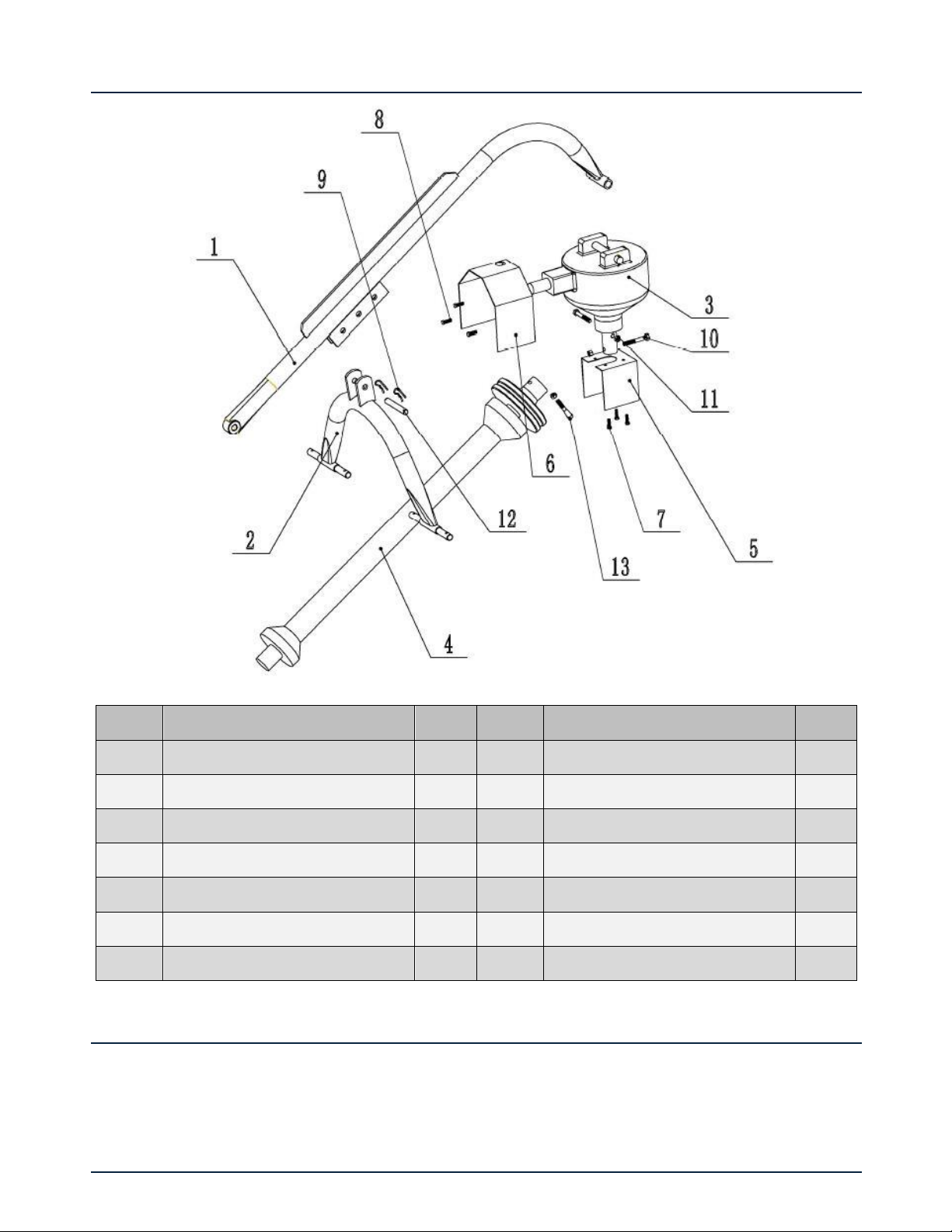
PHD25 PARTS DIAGRAM / EXPLODED VIEW
ASSEMBLY INSTRUCTIONS
−POST HOLE DIGGER COMES FULLY ASSEMBLED
PHD50 PARTS DIAGRAM / EXPLODED VIEW
KEY
DESCRIPTION
QTY
KEY
DESCRIPTION
QTY
(1)
BOOM COMPLETE
1
(8)
BOLT 3/8”X1”
3
(2)
ARCH COMPLETE
1
(9)
COTTER PIN
2
(3)
GEARBOX
1
(10)
BOLT M12X90
2
(4)
PTO SHAFT
1
(11)
LOCKED NUT M12
3
(5)
OUTPUT SHIELD
1
(12)
PIN
1
(6)
PTO COVER
1
(13)
BOLT M12X70
1
(7)
BOLT 3/8”X5/8”
3

6
ASSEMBLY INSTRUCTIONS
−POST HOLE DIGGER COMES FULLY ASSEMBLED
KEY
DESCRIPTION
QTY
KEY
DESCRIPTION
QTY
(1)
BOOM COMPLETE
1
(8)
BOLT 3/8”X5/8”
3
(2)
ARCH COMPLETE
1
(9)
COTTER PIN
2
(3)
GEARBOX
1
(10)
BOLT M12X90
2
(4)
PTO SHAFT
1
(11)
LOCKED NUT M12
3
(5)
OUTPUT SHIELD
1
(12)
PIN
1
(6)
PTO COVER
1
(13)
BOLT M12X70
1
(7)
BOLT 3/8”X5/8”
4

7
ASSEMBLY INSTRUCTIONS
1. Attach arch to lower hitch points. If tractor has Category 2 hitch, use bushings provided on
arch pins
2. Attach arch to boom with pin and cotter pins provided
3. Attach gearbox to boom with pins and cotter pins provided
4. Attach PTO shielf to top of gearbox with bolts provided
5. Prepare PTO for attachment
6. Remove any foreign material or paint from input shaft on gearbox
7. Separate PTO driveshaft. Use a good grade of gun grease and put a light coat on U-joint drive
shaft. Then insert into drive tube
8. Attach PTO to gearbox
9. Make sure roll poin is in groove of input shaft but not tight against bottom of groove so yoke
will rotate freely
10. Put in shear bolt
11. Place snap yoke on tractor pto
12. Raise and lowerthe boom through its complete operation arch and check that nothing
interfers with th e operation. If anything interferes make the proper three-point adjustment
13. Attach the output shaft shield to lower gearbox
14. Attach the auger to gearbox using bolt, lockwashers, and hex nuts provided

8
OPERATING INSTRUCTIONS
1. Lower auger point slowly to ground. Auger point should be 4” to the rear of the plumb line of
the venter of the top of the auger.
2. Set brake or use park position
3. Engage pto shaft clutch at half throttle and slowly lower auger into the ground. In some types
of soil it may be necessary to hold auger back from screwing itself into the ground with the
hydraulic control lever.
4. In some tpyped of soil, for best cleaning action, allow auger to dig a foot or so and raise auger
almost out of the ground and then dig deeper. Repeat as necessary.
5. When the auger has reached the desired depth, leave auger at this depth for a very short
period to assist in cleaning out th ehole.
6. If shear bolt shears, replace with manufacturees shear bolt or qirh onw qirh rhw same
sepecifcations number grade 2.
7. If auger comes lodged nelow the ground, DO NOT attempt to lift auger out of the ground by
hydraulic lift power alone. Reverse the rotation of the auger by several turns. This can be
accomplished by using a bar on the universal joints. After freeing the auger, slowly lift with
auger slowly rotating.
8. DO NOT transport digger with PTO shaft engaged. This may result in damage to universal
joints.
9. Check post hole digger daily for any damaged or loose bolts, securing pins, etc.
LUBRICATION SCHEDULE
1. Fill the post hold differ gearbox with SAW 90 EP oil and check periodically to maintain correct
oil level
2. After the first fifty hours it is recommended that the gearbox be drained, flushed, and refilled
with SAW 90 EP oil. Then every 250 hours.
3. Universal joints must be greasted after digging 300 holes. Tube and shaft should be greased
every other time.

9
ACKNOWLEDGEMENT OF RISK AND RELEASE OF LIABILITY
The use of any equipment, including this one, involves the potential risk of injury. Apart from any
warranty claim that might be presented for a claimed defect in material or workmanship of the product,
you accept and assume full responsibility for any and all injuries, damages (both economic and non-
economic), and losses of any type, which may occur, and you fully and forever release and discharge
Titan, its insurers, employees, officers, directors, associates, and agents from any and all claims,
demands, damages, rights of action, or causes of action, present or future, whether the same be known
or unknown, anticipated, or unanticipated, resulting from or arising out of the use of said equipment.
This equipment must be used with care by capable and competent individuals under supervision, if
necessary.
WARNING
Do not overfill! Mower should be level
when checking oil in gear box.
some activities might be able to cause
electric shock
Sharp objects may be involved.
Use protective cover during maintenance.
TITAN LIMITED WARRANTY: TERMS, EXCLUSIONS AND LIMITATIONS OF REMEDIES
This product comes with a one (1) year limited warranty that can be found at
www.palletforks.com/warranty.html. Please review the same for all details regarding the Titan Limited
Warranty.
THE TITAN LIMITED WARRANTY FOUND AT WWW.PALLETFORKS.COM/WARRANTY.HTML IS
EXCLUSIVE AND IS IN LIEU OF ALL OTHER WARRANTIES, EXPRESS OR IMPLIED, INCLUDING ANY
IMPLIED WARRANTY OF MERCHANTABILITY AND/OR FITNESS FOR A PARTICULAR PURPOSE, EACH
OF WHICH IS HEREBY DISCLAIMED.

10
NEED HELP? CONTACT US FIRST.
1-800-605-7595
www.palletforks.com
© 2023 Titan Brands
This manual suits for next models
15
Table of contents
Other Titan Attachments Construction Equipment manuals


