Permaquip LBR63 Manual

MAN-M-O-209_07 22/11/2013 Page 1of 10
Operating and Maintenance Instructions
LBR63 Rail Lifter
Permaquip Ltd
Brierley Industrial Park, Stanton Hill,
Sutton-In-Ashfield, Nottinghamshire, NG17 3JZ
Tel: +44 (0) 1623 513349
Fax: +44 (0) 1623 517742
E-mail: [email protected]
www.permaquip.co.uk

MAN-M-O-209_07 22/11/2013 Page 2of 10
CONTENTS
1. ISSUE AND REVISION RECORD ................................................................. 3
2. INTRODUCTION ........................................................................................... 4
3. SAFE AND CORRECT USE.......................................................................... 4
4. TECHNICAL SPECIFICATION ...................................................................... 5
5. SPECIAL FEATURES.................................................................................... 5
6. OPERATING INSTRUCTIONS ...................................................................... 6
7. MAINTENANCE............................................................................................. 8
8. EXPLODED VIEW ......................................................................................... 9
9. PARTS LIST .................................................................................................. 9
Please note
Whilst Permaquip Limited has taken every care in preparing this operating and maintenance instruction it is
intended as a technical guideline only. Save to the extent that there are statutory rights to the contrary,
Permaquip accepts no liability in relation to any use or reliance made of any information in this operating and
maintenance instruction.
All information, illustrations and specifications in this operating and maintenance instruction are based on the
latest information available at the time of publication. The right is reserved to make changes at any time without
notice.
Equipment operators and installers shall be responsible for ensuring that a safe working environment and safe
systems of work are in place and in certain circumstances advice and permission from the controlling authority
must be sought before any operation, installation or surveying work is carried out.
Permaquip™ is a trademark of Permaquip Ltd.
©2006 Permaquip Ltd.

MAN-M-O-209_07 22/11/2013 Page 3of 10
1. ISSUE AND REVISION RECORD
This document will be updated when necessary by the re-issue of the complete
document.
Issue
Description
Date
Revised
Page No.
Revised
By.
07
Updated to latest standards
27/11/2013
All
M.S.

MAN-M-O-209_07 22/11/2013 Page 4of 10
2. INTRODUCTION
Congratulations on the purchase of your new Rail Lifter. This is a high quality
product and has a number of unique features to make it the best solution for
your permanent way lifting requirements.
The Rail Lifter has been designed with four height settings and can be used for
lifting various types of rail - UIC 60 and 113lb flat bottom.
These instructions provide information on the correct assembly and use of the
Rail Lifter and must be read and understood by all those required to use it.
3. SAFE AND CORRECT USE
Please keep this User Guide for future reference.
To ensure safe and correct use of the Brake Test Tools the following should be
noted:
Wear feet protection when using the Rail Lifter. Additional Personal
Protective Equipment (PPE) should be worn according to local
regulations.
During transit Rail Lifter should be retained in a tool bag or similar
container, and kept away from all electrified lines.
The Rail Lifter must be replaced or parts replaced using Permaquip
approved parts if any component becomes damaged.
Store the Rail Lifter in a safe secure position.
Do not use the Rail Lifter for any other purpose than as described in
the introduction.

MAN-M-O-209_07 22/11/2013 Page 5of 10
4. TECHNICAL SPECIFICATION
LBR63 Rail Lifter
Height
1200mm
Width
380 mm
Depth
75 mm
Mass
14 kg
Lifting Capacity
1000kg (max)
Proof Load
2500kg
5. SPECIAL FEATURES
The Rail Lifter can be configured to lift different types of rail by altering the
positions of the support legs and connector plates.
The rail is lifted and supported securely when the handle is positioned in the
over-centre position.
The Rail Lifter has 4 different height settings that work with increments of 25mm.
Laser cut profiles ensure smooth controlled movement is possible when
operating the Rail Lifter.

MAN-M-O-209_07 22/11/2013 Page 6of 10
6. OPERATING INSTRUCTIONS
Before operating the Rail Lifter, the following checks must be carried
out:
Check that the rail lifter is fitted with a valid test date plate.
Check that the unit is working correctly. Move the handle up and down and
ensure that the lifting arms move.
Check the condition of the lifting arm profile bodies, ensure that there is no
excess wear and that it has no cracks or splits in it.
Check that all the clevis pins have the lynch pins and seloc pins fitted. If
there is any missing, replace before use.
Check for any other visual damage to clevis pins, handle, framework etc. or
missing components.
Report any defects to the site person in charge.
Rail Lifter Operation.
Set the tool to the desired height. See the images below for the most common
settings.
113lb Setting (left hand top hole) UIC60 Setting (right hand top hole)

MAN-M-O-209_07 22/11/2013 Page 7of 10
Ensure that a minimum of 5 sleepers are unclipped on each side of
the point being lifted, to prevent the unit from being overloaded. If
the unit is being used on wooden sleepers, the condition of the
sleepers must be assessed before lifting can commence.
Position the Rail Lifter over the track with the support legs over each side as
shown.
Once the Rail Lifter has been positioned over the rail and resting on a sleeper,
the rail is ready to be lifted. Rotate the handle across and down until the lifting
arms start to contact the rail. Check that the lifting arms are located securely
under the rail head before continuing to move the handle. Continue to rotate the
handle down towards the ground until it passes its centre position and reaches
the end of its stroke.
Note: When the handle is in the lowered position i.e. with the rail
raised, it is possible to release the handle and leave the lifter
unattended. This is not good practice because if the lifter is
subjected to a jolt or is knocked, it is possible for the handle to
swing up. This can result in serious injuries. It is up to the operator
to ensure that if the lifter is left unattended the handle should be left
in the raised position i.e. rail lowered.
Once work is complete the handle can be lifted and rotated in the opposite
direction in order to lower the rail back down on to the sleeper. Continue to
rotate the handle until the Rail Lifter is released from the rail.
All relevant PPE should be worn and lifting recommendations
followed closely to avoid any injuries. Safety boots, gloves, safety
goggles and helmet should be worn.

MAN-M-O-209_07 22/11/2013 Page 8of 10
7. MAINTENANCE
It is recommended that the following checks are carried out before using the Rail
Lifter:
a) Ensure that the Rail lifter is fitted with a valid, in date test plate. The Rail Lifter
should be tested in accordance with the current LOLER regulations. Currently
this is on a 6 monthly basis.
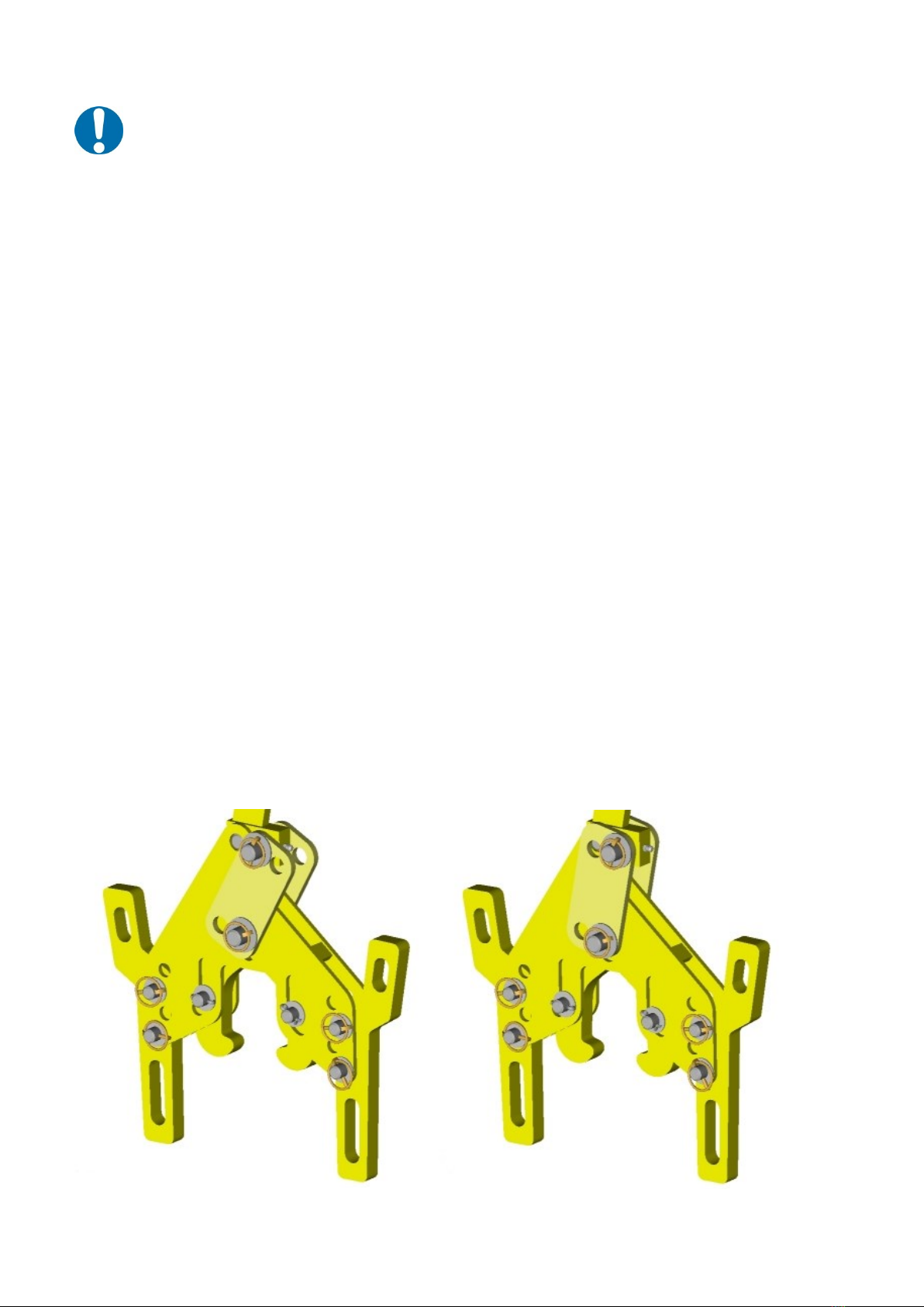
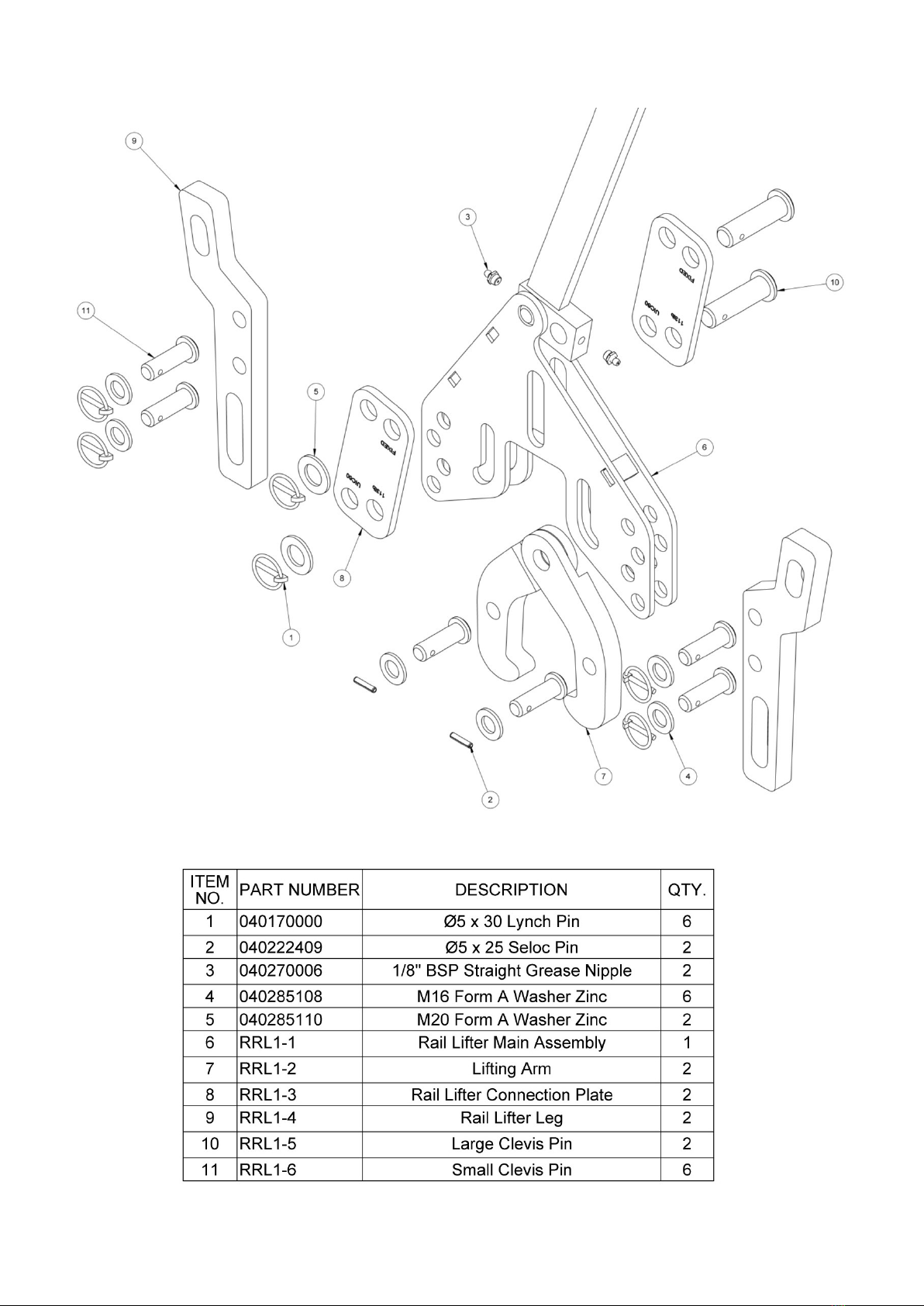
b) Before using the rail lifter, operate the unit and check for signs of wear in all
of the pivot pins, moving parts and the cam guide slots on the main body.
Ensure that it is working correctly and that the play in the pivot pins is not
excessive.
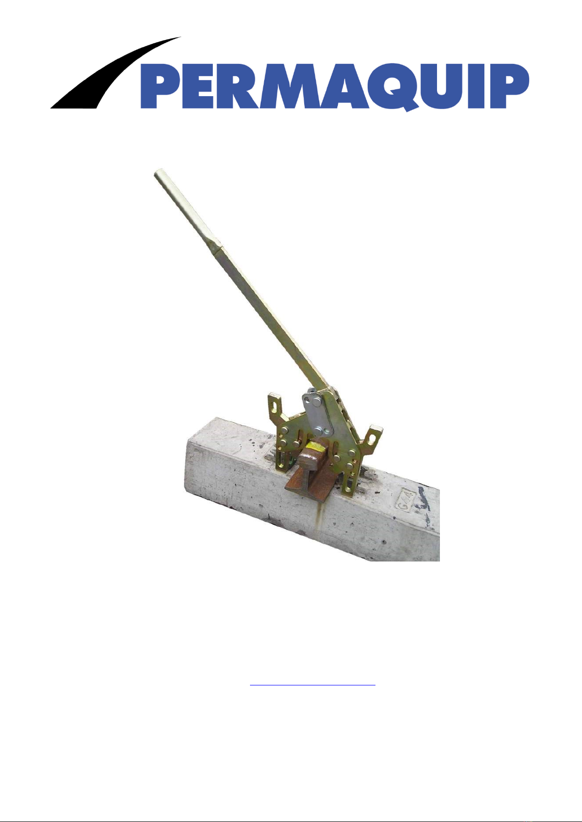
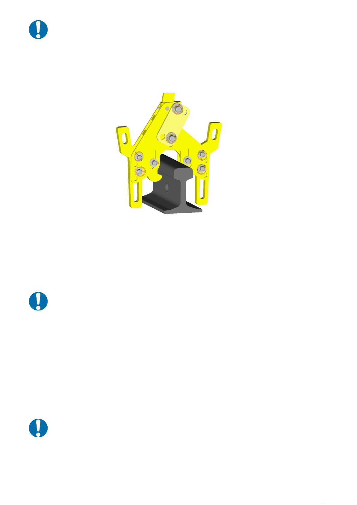
c) Before using the rail lifter, check the condition of the lifting arms. (item 2 on
exploded view) Ensure that the arms are not broken, cracked or excessively
worn.
d) The upper most pivot pins in the assembly must be greased on a weekly
basis using EP32 grease or equivalent. Grease nipples (item 11 on exploded
view) are fitted to the handle to facilitate the greasing of the pins. It is
permissible for the handle to have 2-3mm of vertical travel before it is
necessary to fully refurbish the rail lifter.
e) Ensure that the unit has been set correctly for the type of rail/sleepers being
used:- i.e G44 concrete / UIC60
G44 concrete / 113lb
(See section 6, for the various configurations.)
f) Ensure that all of the pivot pins are secured and held in position using their
retaining pins. These should be seloc pins and lynch pins. If any pivot or
retaining pins are missing the tool should not be used under any
circumstances.
g) Check the condition of all of the pivot pins on a weekly basis. It is permissible
for the pins to wear to a minimum diameter of Ø14mm.
h) Ensure that all of the parts are fitted and are in good condition.
i) Ensure that all moving parts are greased on a weekly basis. Use EP32
grease.
All maintenance or adjustments carried out on this lifting equipment
should only be done by suitably qualified and trained personnel.

MAN-M-O-209_07 22/11/2013 Page 9of 10
8. EXPLODED VIEW
9. PARTS LIST

MAN-M-O-209_07 22/11/2013 Page 10 of 10
Our contact details are shown on the front of this User Guide.
In order to avoid delay and to have your orders fulfilled promptly,
Please telephone, e-mail, fax or write giving the following information:
1. Company name.
2. Contact details.
3. Invoicing and delivery details.
4. Purchase order number.
5. Method of delivery.
6. Part number, description and quantity for each item.
Table of contents
Other Permaquip Construction Equipment manuals
Popular Construction Equipment manuals by other brands

HYVA
HYVA Amco Veba 812 WARNING, OPERATING AND MAINTENANCE MANUAL

hymer
hymer 6773 Instructions for use

Manitowoc
Manitowoc 12000-1 Operating/Service/Maintenance Manual

RHINO
RHINO PD-39P Operating/service instructions

EUROPRO
EUROPRO Compact-Pro 30 BASIC user manual

Z.I.P.P.ER MASCHINEN
Z.I.P.P.ER MASCHINEN ZI-BR160Y user manual