Titan Controls Atlas 2 User manual
Atlas®2
Preset CO2 Monitor/Controller
Instruction Manual
www.titancontrols.net
Notes:
_________________________________________________
_________________________________________________
_________________________________________________
_________________________________________________
_________________________________________________
_________________________________________________
________________________________________________
1 Square = ____ Foot/Feet
®
www.titancontrols.net
VANCOUVER, WASHINGTON U.S.A.
Revision F – 3/12/2012 © Titan Controls®
VANCOUVER, WASHINGTON U.S.A.

Atlas 2®
• Warnings
• Atlas 2®–Preset CO2 controller Overview
• Instructions for Operation
• Calibration Mode
• Error Mode
• Controller Specications
• Installation Examples
• Warranty Information
• Service and Repair Program
Warnings:
• Read all instructions before operating controller.
• Do not put your controller in an area where it can get wet or sprayed.
• Mount your controller securely to the wall using hardware provided.
• When using “bug bombs” in area, cover controller completely to avoid corrosion.
• Do not put paperclips, tools, etc. into unit. Possible electrocution may occur.
• Make sure to verify the voltage, amperage and hertz of the power source prior to plugging in
and activating the controller.
• Check that all devices that will be activated by this controller are the proper voltage.
• This controller is designed for ‘Inside Use’ only.
• Avoid placing the controller near heat generating sources.
• Use caution when operating controller in extremely humid environments.
• Do not use controller for purposes other than the unit was designed to function.
• Use controller within dened environmental specications.
• Ask your Dealer for tips and techniques regarding the use of this controller.
• Be conscientious when disposing of any products.
• Enjoy your Titan Controls® CO2 controller for years to come!
Atlas 2®Preset CO2
Monitor/Controller Overview:
The Titan Controls®Atlas 2® CO2 preset CO2 controller monitors, maintains and displays the
CO2 concentration in your growing environment. The CO2 readings are displayed by four
green LED’s, with each LED indicating a minimum CO2 concentration. The Atlas 2® is equipped
with a photocell, LED display and a one button calibration that calibrates the Atlas 2® to the
approximate concentration of outside air.
WARRANTY SERVICE: Please read warranty information first.
If after reviewing the troubleshooting tips the unit will still not work, you should return it to the
Dealer where you purchased the controller. They will be able to further evaluate the unit and test
its various components and quite possibly will be able to identify and/or x any problems. If the
Dealer is unable to x the unit, they will return it to us for factory repair.
If there are no Dealers in your area, you may contact us directly for technical support. If we can-
not help you resolve the problem over the phone, we will issue you a RMA # (return merchan-
dise authorization) authorizing you to return the unit to us for factory reconditioning (if the unit
is under warranty). Contact the number below for a RMA and shipping address. Complete the
form below and include it with your unit. Also please write the RMA # on the outside of the box.
Please package the unit in its original packaging. If it is damaged in shipment we cannot be
responsible.
Once we receive the unit back, we will repair the controller within 48 hours (business) and return
it to you freight prepaid via UPS ground shipment.
Include the following if returning directly to Titan Controls®
• Proof of purchase • This completed form • RMA # on the outside of the box
Return Merchandise Authorization Number (Required)
Company Name: ____________________________________________________________________________________
Contact Name: _____________________________________________________________________________________
Address: __________________________________________________________________________________________
____________________________________________________________________________________________________
Phone #: ___________________________________________________________________________________________
Email address: _______________________________________________________________________________
What is the nature of the problem? ______________________________________
___________________________________________________________
___________________________________________________________
___________________________________________________________
___________________________________________________________
___________________________________________________________
Send to your nearest location – shipping address will be given when the RMA # is issued.
www.titancontrols.net
For technical assistance call us at 1-888-80-Titan or 1-888-808-4826.
®

Instructions for Operation:
The Atlas 2® is equipped with a photocell that changes how the controller operates depending on the light
in the room.
Day time:
The Atlas 2® has a preset CO2 set point of 1500 PPM (Parts per Million) with a 100 PPM dead band.
When the CO2 concentration in your room drops below 1400 PPM the ‘load’ output will be enabled,
activating the 120 VAC output. When the CO2 concentration rises above 1500 PPM the ‘load’ output will
be disabled.
Night time:
The ‘load’ output of the Atlas 2® is disabled in the night time period (when your grow room is dark);
however the controller will continue to monitor and display your grow rooms CO2 level.
How the Atlas 2®works!
The Atlas 2® has four (4) green LED’s that are used to display the CO2 concentration in your grow room.
An illuminated LED shows that the concentration is at least the PPM noted under the LED. As the CO2
rises in your grow room, the LED’s showing the indicated concentration will remain illuminated.
If the Atlas 2® has the ‘load’ output ‘ON’, the illuminated LED’s will quickly ash twice approximately every
three seconds. If the controllers load output is ‘OFF’, the illuminated LED’s will remain solid on.
Display CO2 below 1000 PPM:
If the CO2 concentration is below 1000 PPM (Figure 1) all
LED’s will be off; however the 1000 PPM LED will ash one
(1) time approximately every three (3) seconds to indicate that
the sensor is functioning properly. If the load output is ‘ON’,
the 1000 PPM LED will ash two (2) times approximately every
three (3) seconds.
Display CO2 between 1000 PPM and 1249 PPM:
Figure 2 shows how the CO2 will be displayed if the CO2
concentration is above 1000 PPM but below 1250 PPM. If the
load output is ‘ON’, this LED will quickly ash two (2) times
every three (3) seconds.
Display CO2 between 1250 PPM and 1499 PPM:
Figure 3 shows how the CO2 will be displayed if the CO2
concentration is above 1250 PPM but below 1500 PPM. If the
load output is ‘ON’, these LED’s will quickly ash two (2) times
every three (3) seconds.
Warranty Information:
• Titan Controls® warrants the original purchase of this product against defects in material and
workmanship under normal use for three (3) years from the date of purchase.
• During the warranty period, Titan Controls® will, at our option, and without charge, repair or
replace this product if the controller or any of its components fail or malfunction.
• All returns or repairs must be accompanied by a Return Merchandise Authorization (RMA)
number prior to any service of the product.
• This warranty is expressly in lieu of all other warranties, expressed or implied, including the
warranties of merchantability and tness for use and of all other obligations or liabilities on the
part of the seller.
• This warranty shall not apply to this product or any part thereof which had been damaged by
accident, abuse, misuse, modication, negligence, alteration or misapplication.
• Controllers with serial numbers or date tags that have been removed, altered or obliterated;
broken seals or that show evidence of tampering; mismatched board serial numbers or
nonconforming parts; are excluded from coverage.
• Titan Controls® makes no warranty whatsoever in respect to accessories or parts not supplied
by Titan Controls®.
• Monetary refunds of the warranty will not be given.
• The Buyer assumes all responsibility regarding the use & installation of this controller.
• All warranty service is provided through the factory or an authorized service representative.
• This warranty shall apply only to the United Sates, including Alaska, Hawaii and territories of
the United States.
• Defective controllers need to be returned with the “proof of purchase” receipt.
• For additional warranty information, contact a Titan Controls® Technical Service
Representative or your Dealer.
• NOTE: Titan Controls® is a controller manufacturer. All sales offerings to the public are done
through a nationwide group of Dealers. No sales offerings will be made directly to the general
public.
Service and Repair Program:
• For all service and repairs please contact our Technical Service Representative for a Return
Merchandise Authorization (RMA) number.
• All factory service & repairs will be completed within 48 hours of receipt of controller and after
authorization by customer for repairs.
• Titan Controls® will, at its discretion, repair or replace the controller.
• Factory calibration services are available for all Titan Controls®.
• Returning Units: Please contact your retail store for returns.
PHOTOCELL
10
0
0
P
P
M
1250 PPM
1500 PPM
2
500
P
P
M
CALIBRATION
FLASHES
TO INDICATE
ACTIVITY FIGURE 1
PHOTOCELL
10
0
0
P
P
M
1250 PPM
1500 PPM
2
500
P
P
M
CALIBRATION
FIGURE 2
PHOTOCELL
10
0
0
P
P
M
1250 PPM
1500 PPM
2
500
P
P
M
CALIBRATION
FIGURE 3
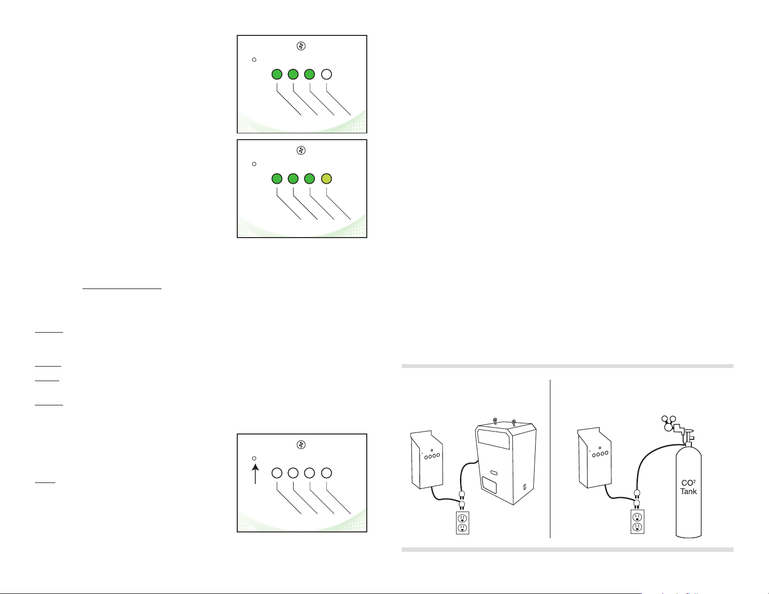
Display CO2 between 1500 PPM and 2499 PPM
Figure 4 shows how the CO2 will be displayed if the CO2 is
above 1500 PPM but below 2500 PPM. The LED’s will be
illuminated but will remain solid.
Display CO2 above 2500 PPM
Figure 5 shows how the CO2 will be displayed if the CO2
is above 2500 PPM. Note: the 2500 PPM LED is a different
shade of green to indicate a higher concentration of CO2
than normal. If this LED is illuminated, you may want to take
a break from working in your room and seek fresh air.
Calibration Mode:
The Atlas 2®is ‘FACTORY CALIBRATED’ and does not require calibration out of the box. Occasionally, it
needs periodic calibration due to ‘drift ‘ in the sensor. This should occur every three (3) years or so. The
Atlas 2® has a single button that is used to place the controller into calibration mode. It will automatically
calibrate itself to the outside air. To properly calibrate the Atlas 2®, follow these simple steps:
Step # 1: Take the Atlas 2® to an outside area where CO2 pollution is at a minimum (avoid areas where
animals, machinery, autos, etc. are located). Try not to breath directly on the Atlas 2®, it will confuse the
calibration process.
Step #2: Power up the Atlas 2®.
Step #3: Allow the Atlas 2® a minimum of ve (5) minutes to stabilize in the outside area. For best
accuracy, be sure to avoid breathing directly on the controller during this time and while it’s calibrating.
Step # 4: Press and hold the “CALIBRATION” button (Figure 6) for approximately three (3) seconds using a
toothpick or matchstick. (Use a non-metallic item to avoid potential shock.) Once the LED’s begin to cycle
back and forth, release the button and allow the unit to complete the calibration process. The calibration
process should take less than two (2) minutes.
After completion of the calibration process, the Atlas 2®will
return to normal operation and the LED’s will display the
current CO2 PPM concentration of the ambient air.
NOTE: Calibrating to outside air provides a good approximate
calibration. The accuracy of the CO2 calibration will be
dependent on the quality of the air that the Atlas 2®sensor
has been exposed to during the calibration process.
Error Mode:
The Atlas 2® will go into an ERROR MODE if the following conditions occur:
• The Atlas 2® is unable to get readings from the CO2 sensor module.
• The Atlas 2® is unable to complete the calibration process properly.
While in the ERROR MODE, the Atlas 2® will disable the ‘load’ output and ash LED’s on, then off, then on,
then off, etc.
To RESET your Atlas 2®, simply unplug from power source, count to 10 and then plug back into power
source. This normally corrects the problem.
Controller Specifications:
• Size = 8”H x 4.5”W x 2.5”D
• Weight = 1 lbs.
• Output Amperage = 15 Amps Resistive
• Voltage Input = 120 VAC
• Voltage Output = 120 VAC
• Hertz = 60Hz
• Electrical Relay Operations = 10,000 Cycles
• RoHS compliant = Yes
• Storage Temperature = 32°F (0°C) to 135°F (57°C)
• Operating Temperature = 40°F (5°C) to 125°F (52°C)
Installation Examples:
Controlling a CO2 Generator Controlling a CO2 Tank with Generator
CO2
Generator
Atlas 2
Atlas 2
CO2
Generator
Atlas 2
Atlas 2
PHOTOCELL
10
0
0
P
P
M
1250 PPM
1500 PPM
2
500
P
P
M
CALIBRATION
FIGURE 4
PHOTOCELL
10
0
0
P
P
M
1250 PPM
1500 PPM
2
500
P
P
M
CALIBRATION
FIGURE 5
PHOTOCELL
10
0
0
P
P
M
1250 PPM
1500 PPM
2
500
P
P
M
CALIBRATION
FIGURE 6


