TITAN MODEL KITS A330-200 User manual

1:72 A330-200 / -300
Assembly Guide

Thank you for purchasing a Titan Model Kit. These kits are intended for experienced
intermediate to advanced adult scale modelers. Kits will require you to measure, mark, cut,
scratch-build, and modify various pieces. Builders are cautioned to review the assembly
instructions in their entirety prior to beginning any work. These instructions are provided only as
a guide. You may choose to alter the sequence of steps, change techniques, or omit steps at
your discretion. You will find the following tools useful in your build: hobby knife, dial calipers,
ruler or measuring tape, drill with various bit sizes, rotary tool (Dremel or equivalent), sand
paper of various grit, sanding block, styrene model cement (solvent based), and cyanoacrylate
glue (Superglue or equivalent).
Assembly instructions may contain images that do not correspond precisely to the physical kit
parts. Physical parts are in a state of continuous improvement and you may have earlier or later
versions of an individual part or kit than what is shown in the assembly instructions. The images
are intended to provide you with general orientation only. Additionally some images are general
in nature and are used to illustrate concepts which are common to multiple kits.
Screenshots of CAD models are used for concept illustration only and the images may contain
elements that may or may not be present in the physical parts. For instance, cabin window and
door outlines are shown in these images to help in visual orientation and are not present in the
physical parts. Screenshots may omit adjacent parts for clarity.
© Titan Model Kits 2 Revision 1.4 26 Aug 2022

Table of Contents
I. Parts Preparation
A. Vacform Parts
1. Remove parts from sheet
2. Remove stock thickness
3. Thin trailing edges
4. Drill out engine and flap track attachments
5. Cut out wing & tail passthroughs
6. Cut out NACA vent holes
7. Install 90° angle styrene reinforcement strips
8. OPTION: Landing Gear Cutouts
B. Resin Parts
1. Remove support columns
2. Sand support column attach points
II. Assembly
A. General
B. Instructions
1. OPTION: Install wheel wells
2. Install APU
3. Assemble horizontal tail
4. Assemble wing top and bottom
5. OPTION: Install clear cockpit windows
6. Assemble fuselage halves
7. Join the wings
8. Install flap track fairings
9. Install wing roots and wing fillets
10. Install engines
11. OPTION: Assemble and install landing gear
12. Install antennas
III. References
© Titan Model Kits 3 Revision 1.4 26 Aug 2022

I. PARTS PREPARATION
I.A VACFORM PARTS
I.A.1. Remove parts from sheet:
Carefully remove the parts by cutting along the silhouette of the part with a sharp utility
knife. You may find it helpful to mark the cut lines with pencil prior to cutting. Always
cut from the top of the parts, never from the bottom. Multiple shallow passes will always
yield a better result than trying to cut through on a single pass.
.
© Titan Model Kits 4 Revision 1.4 26 Aug 2022
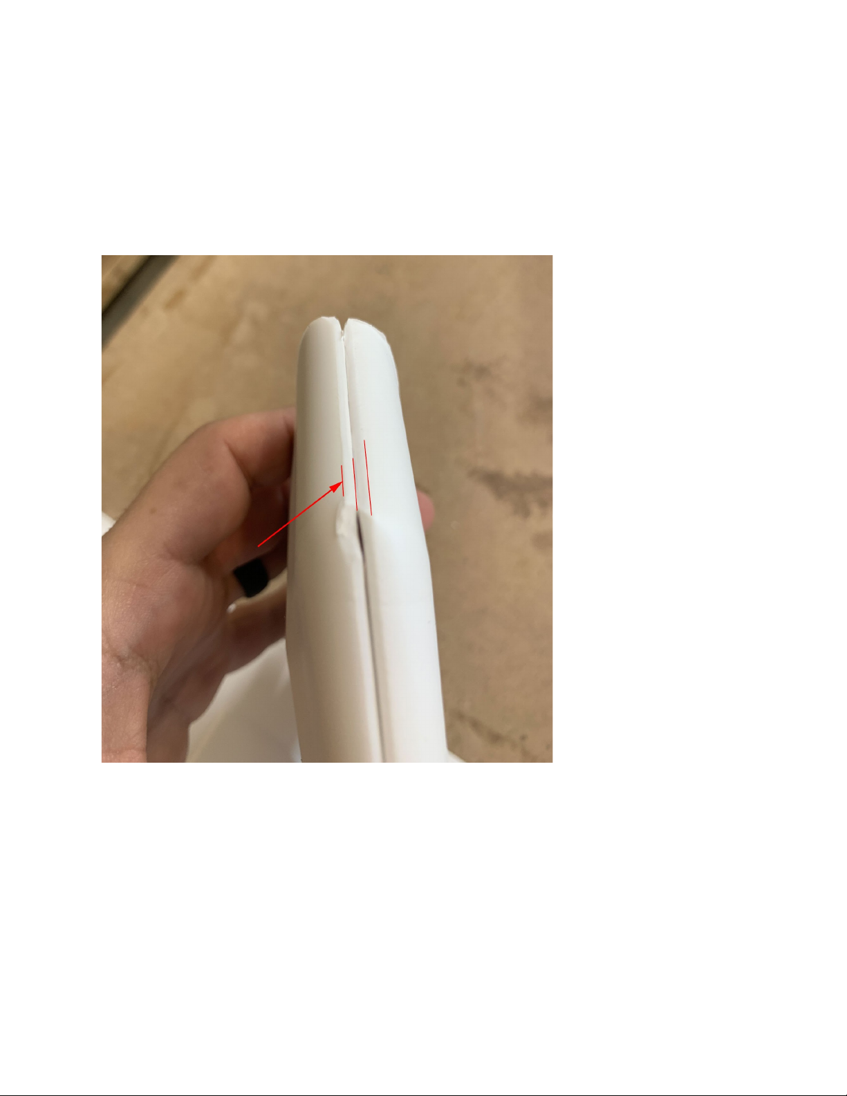
I.A.2. Remove stock thickness:
Once parts are cut away from their sheet they will still need to have the sheet thickness
removed from them. As can be seen from the below photo, the .080” sheet thickness
between the red lines should be removed. Coarse sandpaper in a sanding block is
recommended to remove this material. Work slowly, checking progress often.
© Titan Model Kits 5 Revision 1.4 26 Aug 2022
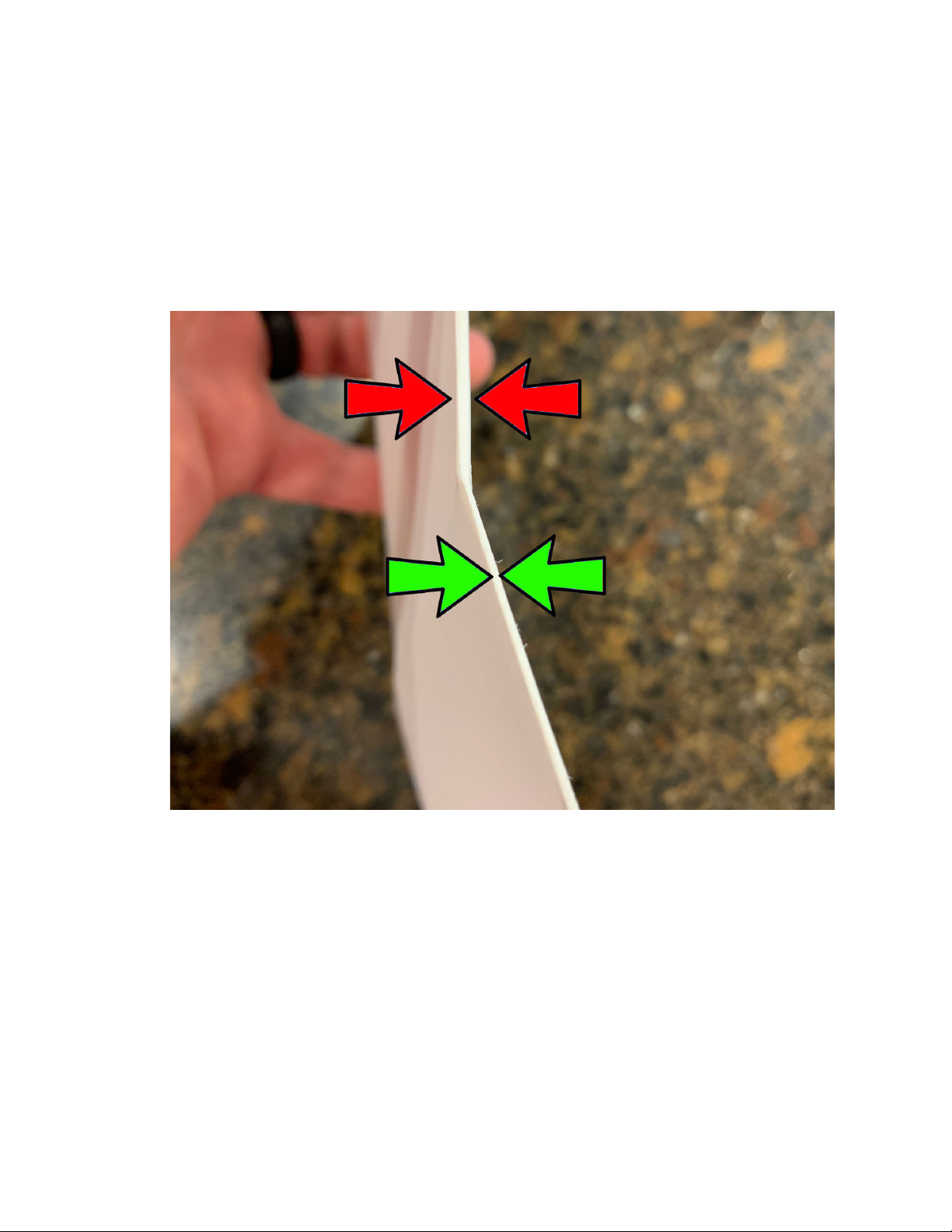
I.A.3. Thin trailing edges:
As delivered, the trailing edges of the wings and tail parts are the thickness of the
plastic sheet used to produce them. If left alone, assembling raw parts will result in a
trailing edge that is too thick for scale. Using 220 grit sandpaper, thin all trailing edges
from the .080” material thickness to approximately .010”. Work slowly, checking
thickness and consistency as you go. This will result in trailing edges that are more
“to-scale”
© Titan Model Kits 6 Revision 1.4 26 Aug 2022
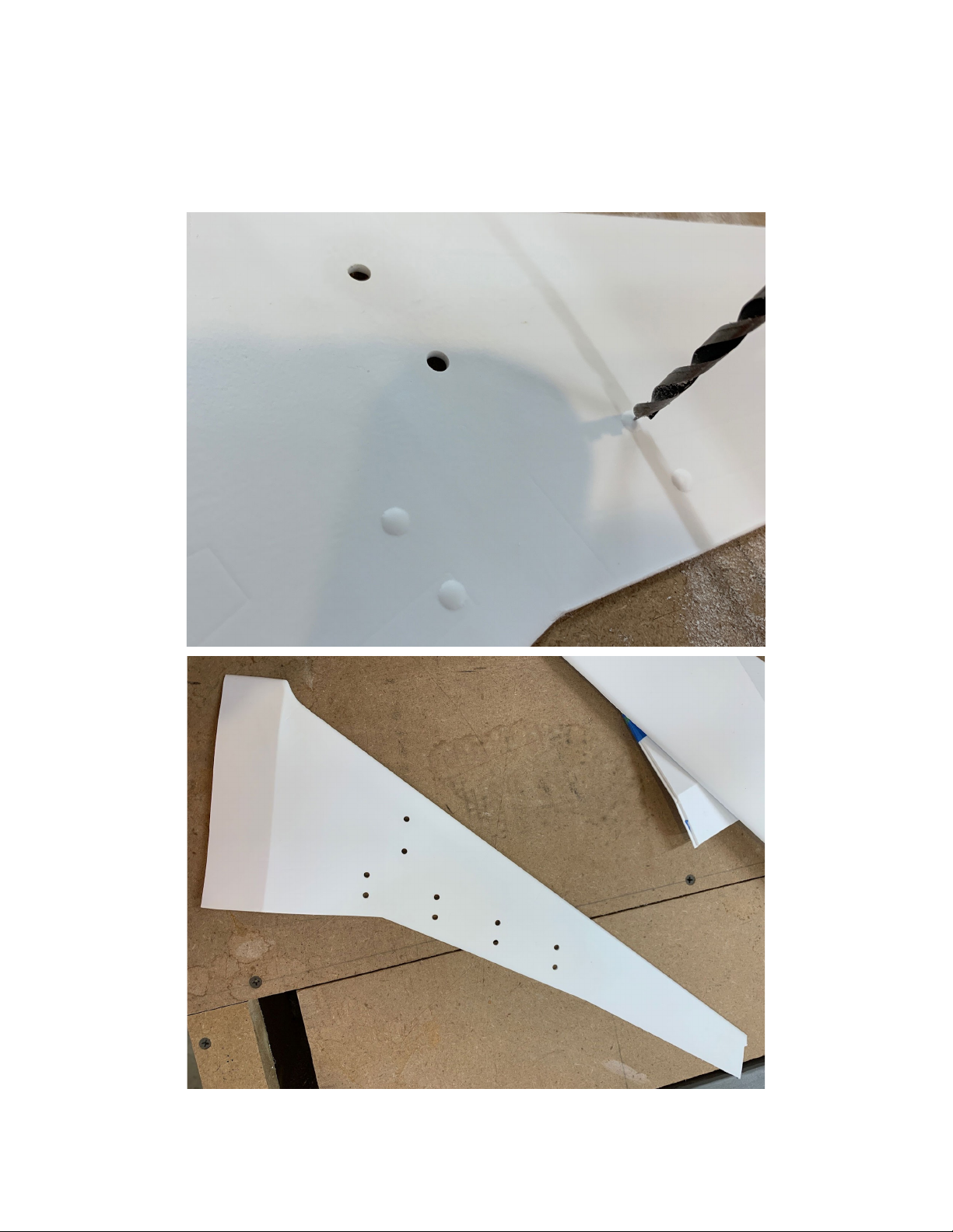
I.A.4. Drill out engine and flap track attachments:
Engine and flap track fairing attachment points should be drilled out with a ⅛” (3mm)
brad-point drill bit. Depending upon your engine selection you may need to enlarge the
holes.
© Titan Model Kits 7 Revision 1.4 26 Aug 2022

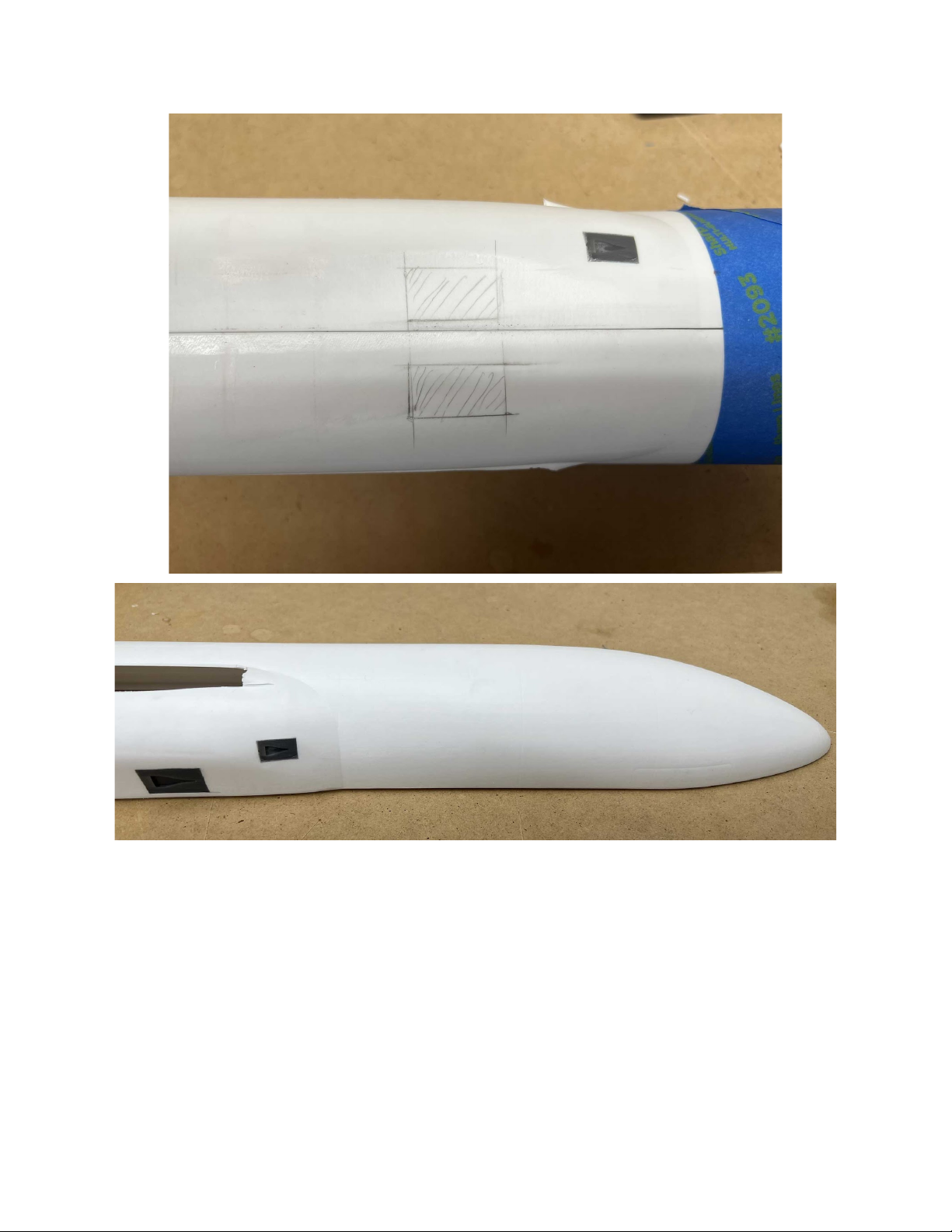
I.A.5. Cut out wing & tail passthroughs
Remove plastic to allow for the wing and tail assemblies to pass through the fuselage
halves as shown. The attached templates can be scaled and used to help you know
exactly where to cut.
© Titan Model Kits 8 Revision 1.4 26 Aug 2022

Wing Passthrough Template
Scale this page with a copy machine to ensure that the block below is exactly 1
inch wide. Use as template to remove material for wing passthrough.
© Titan Model Kits 9 Revision 1.4 26 Aug 2022

Tailplane Passthrough Template
Scale this page with a copy machine to ensure that the block below is exactly 1
inch wide. Use as a template to remove material for tailplane passthrough.
© Titan Model Kits 10 Revision 1.4 26 Aug 2022

I.A.6. Cut out NACA vent holes
3D-printed NACA vents are provided for the ventral fuselage. Measure, mark,
and cut holes in the fuselage halves to allow them to be mounted as shown. Units
shown in the diagram are in inches.
© Titan Model Kits 11 Revision 1.4 26 Aug 2022
© Titan Model Kits 12 Revision 1.4 26 Aug 2022
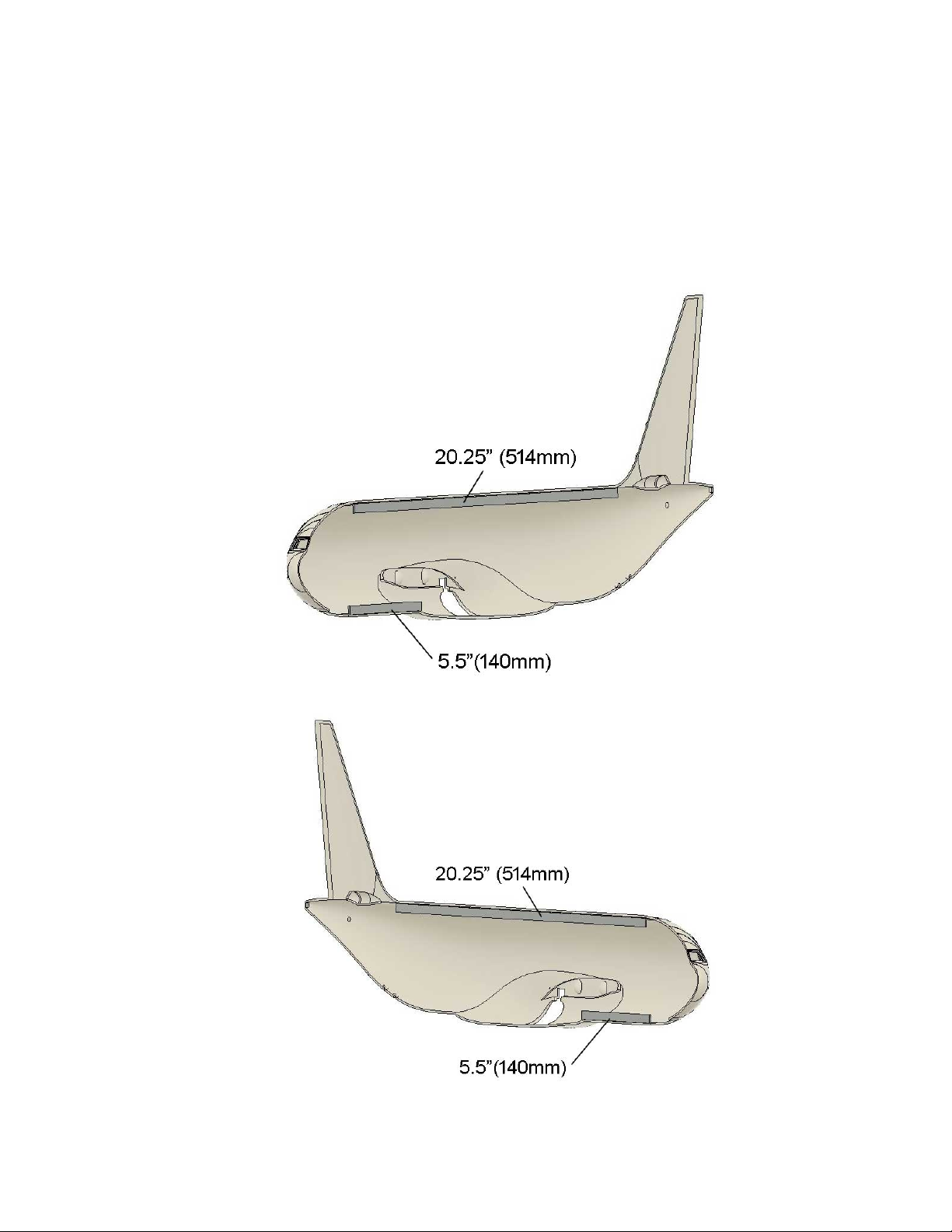
I.A.7. Install 90° angle styrene reinforcement strips
¼” styrene angle strips are provided to add rigidity to the fuselage and to
increase the area of the fuselage joint for glue-up. Install as shown below. Install on
BOTH fuselage halves. You may wish to add additional bracing or joint reinforcement
using scrap styrene at your discretion.
A330-200
© Titan Model Kits 13 Revision 1.4 26 Aug 2022

A330-300
© Titan Model Kits 14 Revision 1.4 26 Aug 2022
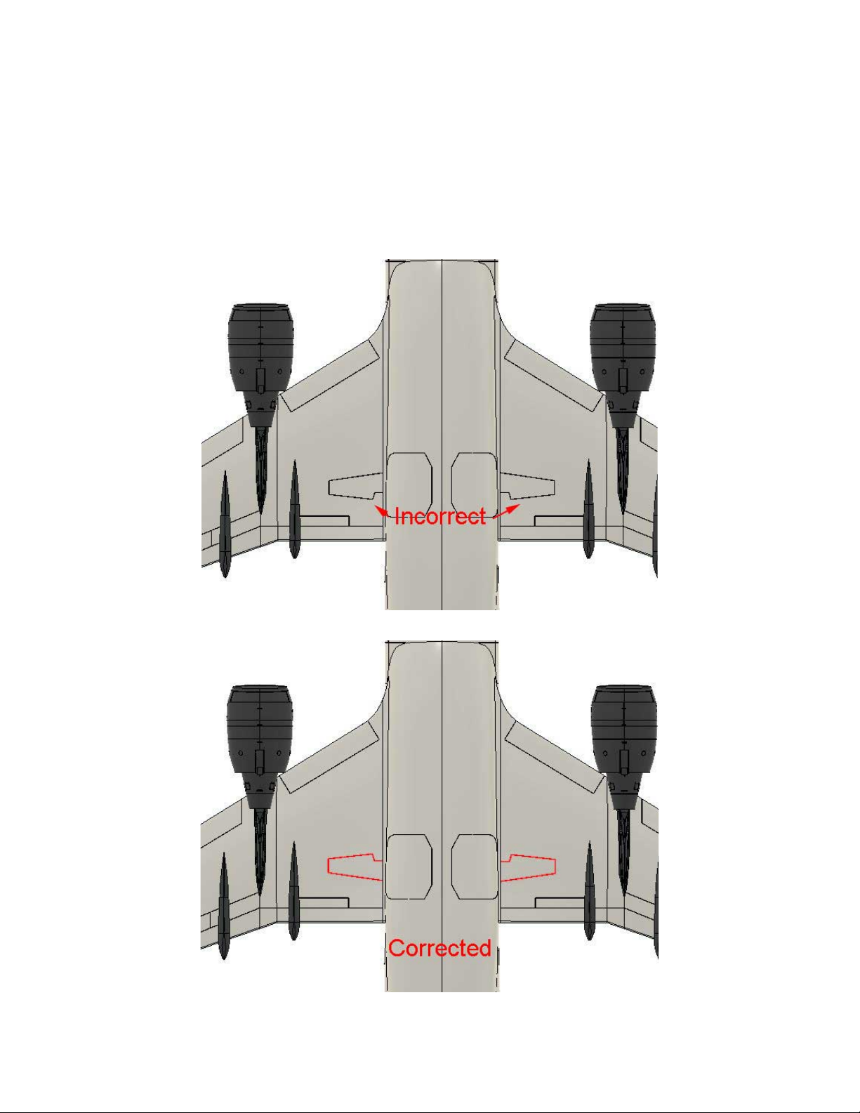
I.A.7. OPTION: Landing Gear Cutouts:
CORRECTION--The main landing gear door panel lines as molded on the wings of
Early production kits (kits produced prior to August 2022) are incorrect. Correct
cutting lines are shown in red on the diagram below. Check to see which version of the
kit you have. If you have an early version, you can use the 3D printed main wheel wells
to help mark where to cut the holes.
© Titan Model Kits 15 Revision 1.4 26 Aug 2022
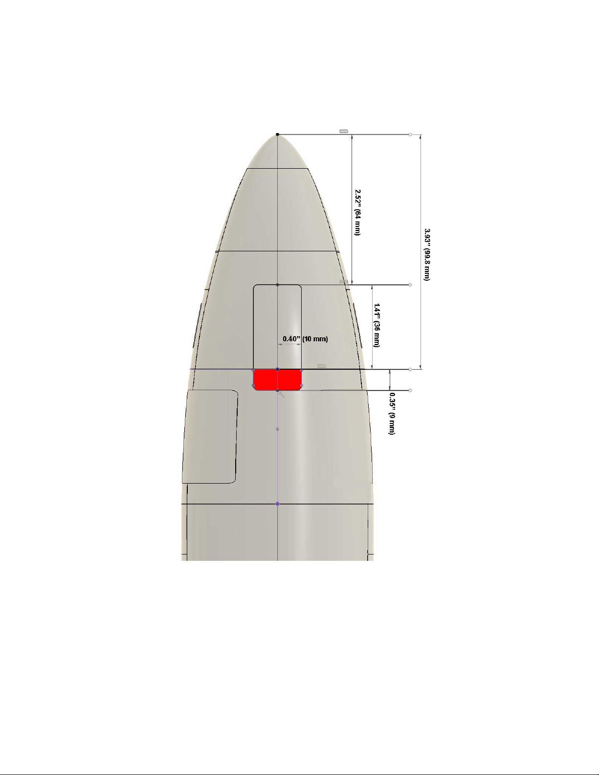
Measurements for Nose Gear Door Cutout
© Titan Model Kits 16 Revision 1.4 26 Aug 2022
I.B RESIN PARTS PREPARATION
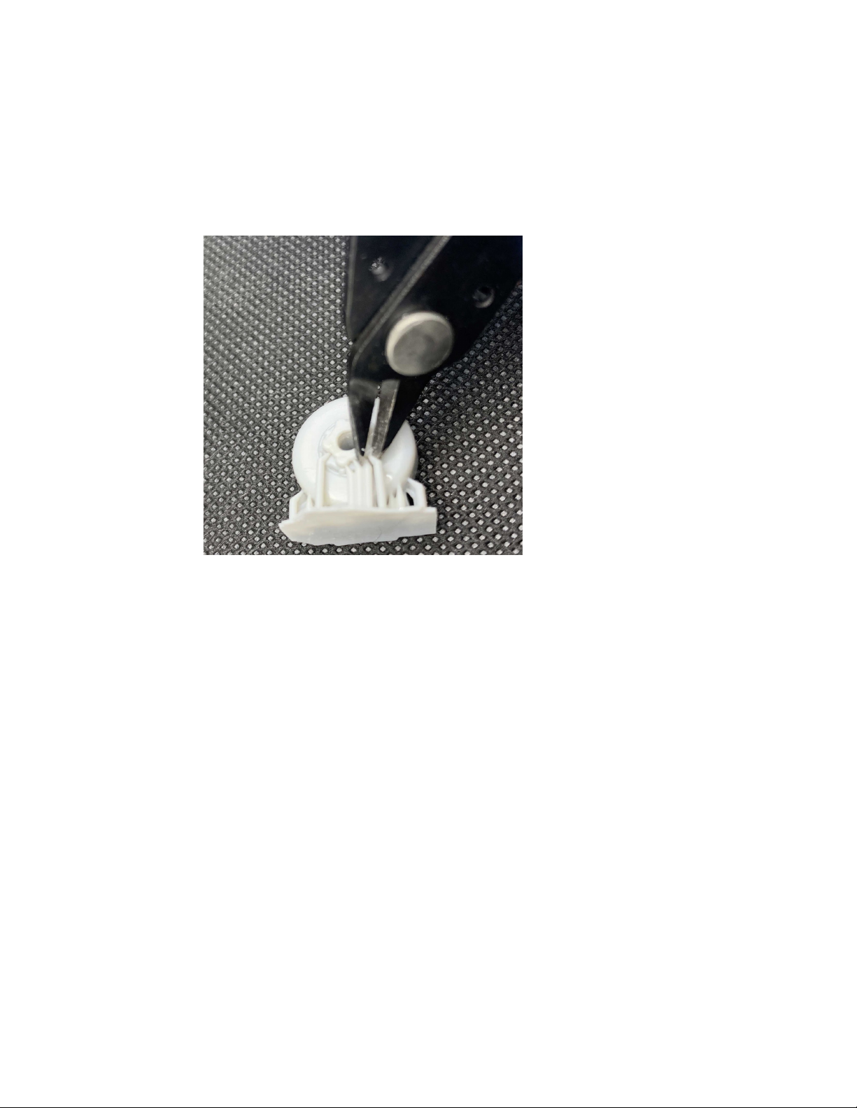
I.B.1. Remove support columns:
Some 3D-printed parts (wheels especially) may come with printer supports still
attached. Carefully remove supports with a utility knife or sprue cutter and gently sand
attachment point dimples away.
I.B.2. Sand support column attach points
© Titan Model Kits 17 Revision 1.4 26 Aug 2022
II. ASSEMBLY
II.A. GENERAL
Vacform parts are made from high impact polystyrene (HIPS) plastic. Vacform parts
should be glued to one another using solvent based ‘glue’. 3D printed parts should be
glued to one another and to vacformed parts using cyanoacrylate (Superglue or
equivalent) or 2-part epoxy.
II.B.1. OPTION: Install wheel wells:
Wheel wells should be installed prior to assembling fuselage halves and wings.
© Titan Model Kits 18 Revision 1.4 26 Aug 2022
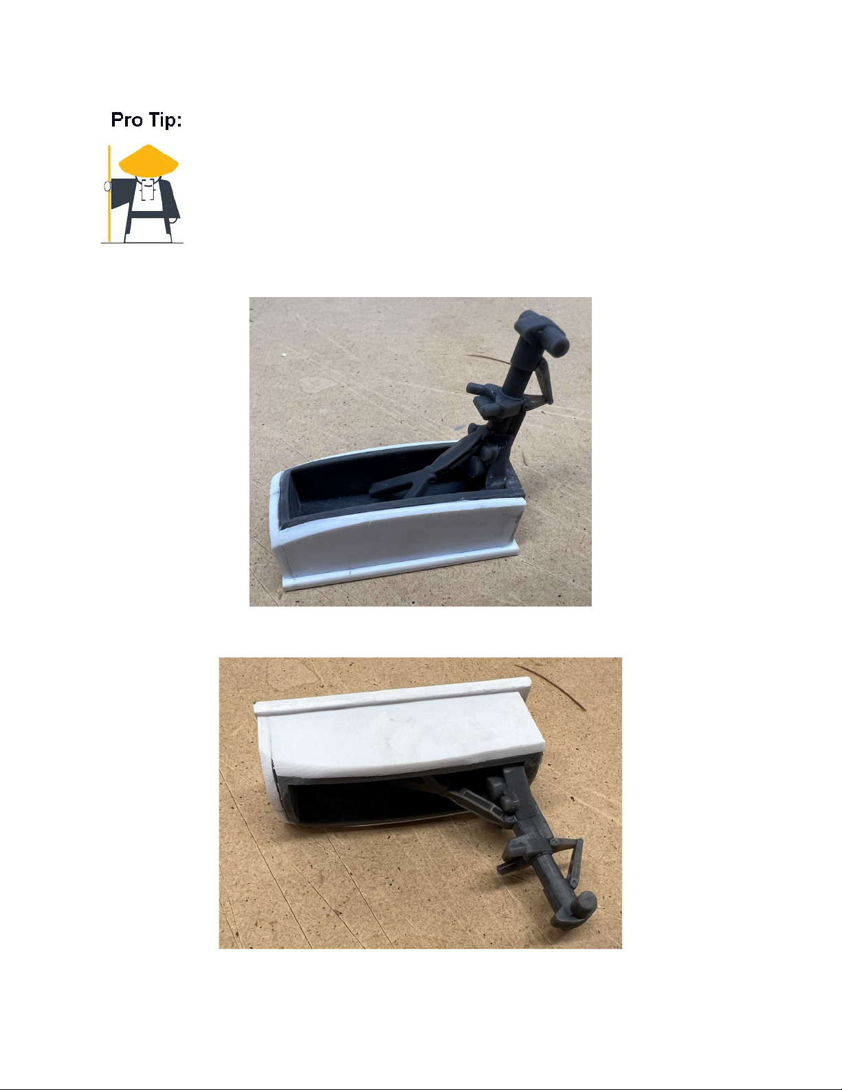
The strongest joint is a chemically welded styrene to styrene joint–one that
is glued with solvent glue. For extremely strong construction use scrap
styrene to ‘wrap’ your wheel wells. This can be done before installing
them, or after and can be done for both the main wheel wells and the nose
wheel well. The goal is to make a styrene box to contain the resin part
and take stress off of the resin-styrene joint.
© Titan Model Kits 19 Revision 1.4 26 Aug 2022
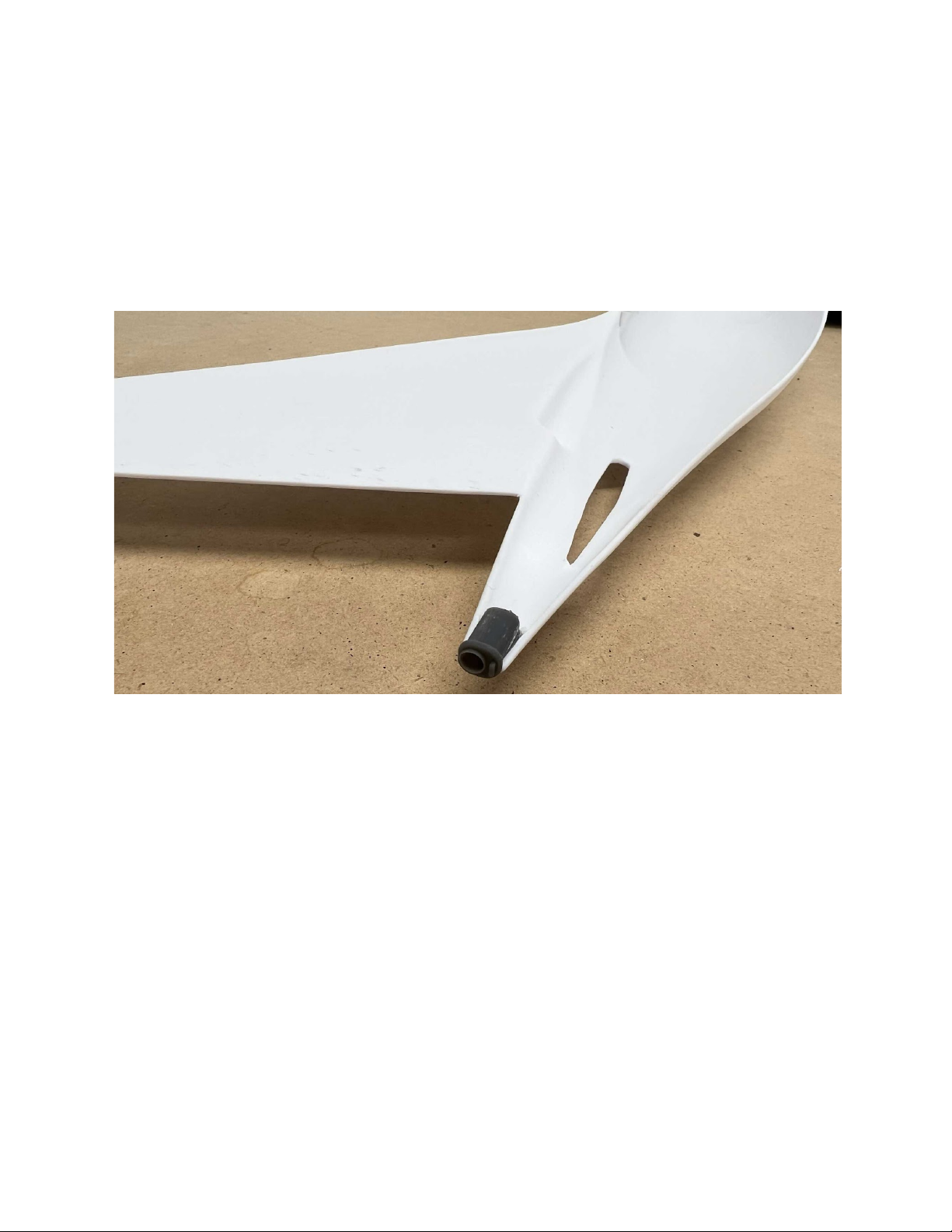
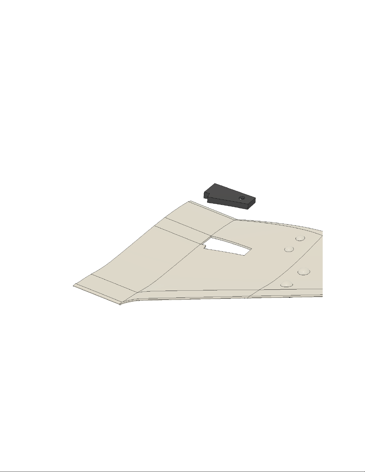
II.B.2. Install APU exhaust
The APU exhaust should be installed prior to cementing the fuselage halves
together. You will need to thin the vacformed part using sandpaper or a rotary
tool with grinding bit in order to accept the resin APU.
© Titan Model Kits 20 Revision 1.4 26 Aug 2022
This manual suits for next models
1
Table of contents
Other TITAN MODEL KITS Toy manuals


