Titan WCBX62S IM-CHUTE62 IM User manual

3PT PTO 6” WOOD CHIPPER
WCBX62S_IM-CHUTE62_IM
198268
Operator’s Manual
Read the Operator’s Manual entirely. When you see this
symbol, the subsequent instructions and warnings are
serious follow without exception. Your life and the lives
of others depend on it!

2
IMPORTANT SAFETY INFORMATION
THESE ARE STANDARD PRACTICES THAT MAY NOT APPLY TO THE PRODUCTS
DESCRIBED IN THIS MANUAL.
SAFETY AT ALL TIMES
Thoroughly read and understand the instructions given in this manual before operation. Refer
to the “Safety Label” section, read all instructions noted on them. Do not allow anyone to
operate this equipment who has not thoroughly read and comprehended this manual. Do not
allow anyone who has not adequately trained in the safe operation of the equipment.
•The operator should be familiar with all functions of the unit.
•Operate implement from the driver’s seat only.
•Make sure all guards and shields are in place and secured before operating the tool.
•Do not leave a tractor or implement unattended with the engine running.
•Dismounting from a moving tractor could cause severe injury or death.
•Do not allow anyone to stand between tractor and implement while backing up to
implement.
•Keep hands, feet, and clothing away from power-driven parts.
•Wear snug-fitting clothing to avoid entanglement with moving parts.
•Watch out for wires, trees, etc., when raising implements. Make sure all persons are clear
of the working area.
•Turning the tractor too tight may cause implement to ride upon wheels. This activity could
result in injury or equipment damage.
•Do not carry passengers on the tool at any time.
LOOK FOR THE SAFETY ALERT SYMBOL
The SAFETY ALERT SYMBOL indicates a potential hazard to personal safety, and individuals
must take safety precautions. When you see this symbol, be alert and carefully read the
message that follows it. In addition to the design and configuration of equipment, hazard
control and accident prevention depend on the awareness, concern, prudence, and proper
training of personnel involved in the operation, transport, maintenance, and storage.

3
BE AWARE OF SAFETY ALERT WORDS
DANGER: Indicates imminently hazardous practices. A situation that, if not avoided, will result
in death or severe injury. The signal word is limited to the most extreme situation, typically for
machine components that, for functional purposes, cannot be guarded.
WARNING: Indicates a potentially hazardous situation that, if not avoided, could result in death
or severe injury, and includes hazards that are exposed when guards remove. Use warnings to
alert against unsafe practices.
CAUTION: Indicates a potentially hazardous situation that may result in minor or moderate
injury if not avoided. It may also be used to alert against unsafe practices.
FOR YOUR PROTECTION
Thoroughly read and understand the “Safety Label” section, read all instructions noted on them.
SHUTDOWN AND STORAGE
•Lower machine to the ground, put the tractor in park, turn off the engine, and remove the
key.
•Detach and store implements in an area where children typically do not play
USE SAFETY LIGHTS AND DEVICES
•Slow-moving tractors, self-propelled equipment, and towed implements can create a
hazard when driven on public roads. They are challenging to see, especially at night.
•Flashing warning lights and we recommend turn signals whenever driving on the public
road.
TRANSPORT MACHINERY SAFELY
•Comply with state and local laws
•The maximum transport speed for implement is 20 mph, DO NOT EXCEED. Never travel at
a rate that does not allow adequate control of steering and stopping. Some rough terrain
requires a slower speed.
•Sudden braking can cause a towed load to swerve and upset. Reduce speed if the towed
load is not equipped with brakes.
Use the following maximum speed – tow load weight ratios as a guideline:
•20 mph when weight is less than or equal to the weight of the tractor.
•10 mph when weight is double the weight of the tractor.
IMPORTANT: Do not tow a load that is more than double the weight of the tractor.

4
KEEP RIDERS OFF MACHINERY
•Riders obstruct the operator’s view; they could be struck by foreign objects or thrown
from the machine.
•Never allow children to operate equipment.
•Practice Safe Maintenance
•Understand procedure before doing work. Use proper tools and equipment; refer to
Operator’s Manual for additional information.
•Work in a clean, dry area
•Lower the implement to the ground, put the tractor in park, turn off the engine, and
remove the key before maintenance.
•Allow implement to cool completely.
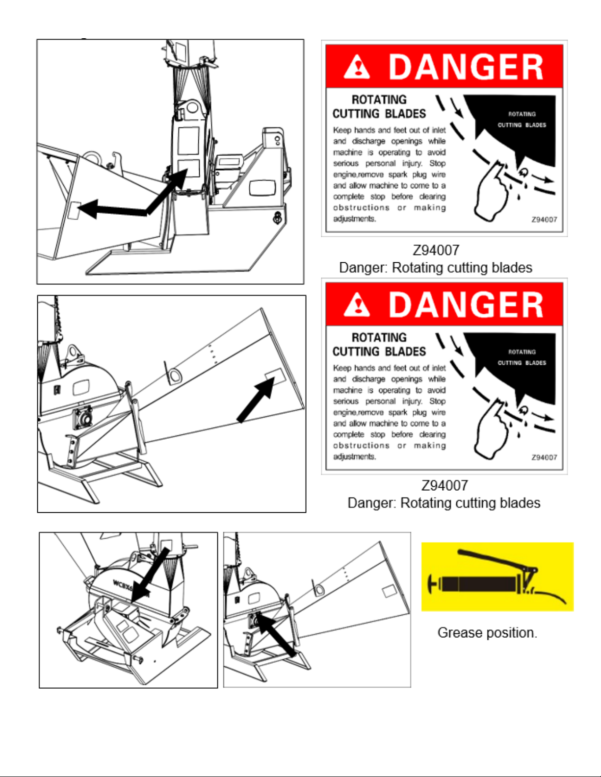
•Do not grease or oil implement while it is in operation.
•Inspect all parts. Make sure details are in good condition and installed correctly.
•Remove the buildup of grease, oil, or debris.
•Remove all tools and unused parts from implementation before operation.
PREPARE FOR EMERGENCIES
•Be prepared if a fire starts.
•Keep a first aid kit and fire extinguisher handy
•Keep emergency numbers for doctor, ambulance, hospital, and fire department near the
phone.
WEAR PROTECTIVE EQUIPMENT
•Wear protective clothing and equipment appropriate for the job. Avoid loose-fitting
clothing.
•Prolonged exposure to loud noise can cause hearing impairment or hearing loss. Wear
suitable hearing protection such as earmuffs or earplugs.
•Operating equipment safety requires the full attention of the operator. Avoid wearing
radio headphones while operating machinery.
AVOID HIGH-PRESSURE FLUIDS HAZARD
•Escaping fluid under pressure can penetrate the skin causing severe injury.
•Avoid the hazard by relieving pressure before disconnecting hydraulic lines or performing
work on the system.
•Ensure all hydraulic fluid connections are tight and all hydraulic hoses and lines are in
good condition before applying pressure to the system.
•Use a piece of paper or cardboard, NOT BODY PARTS, to check for suspected leaks.
•Wear protective gloves and safety glasses or goggles when working with hydraulic
systems.
•If an accident occurs, see a doctor immediately. Remember, any fluid injected into the skin
must be treated within a few hours, or gangrene may result.

5
TIRE SAFETY
•Tire changing can be dangerous, and trained personnel should be the only ones using
correct tools and equipment.
•When inflating tires, use a clip-on chuck and extension hose long enough to allow you to
stand to one side and NOT in front of or over the tire assembly. Use a safety cage if
available.
•When removing and installing wheels, use wheel handling equipment adequate for the
weight involved.
SAFETY LABELS
Your Woodchipper comes equipped with all safety labels in place. They were designed to help
your safety operate your implement. Read and follow their directions.

6

7

8
INTRODUCTION
APPLICATION (WCBX62S)
The WCBX62S woodchipper is built by TITAN to reduce unwanted tree limbs into useful
landscape mulch typically found in flower beds, gardens or just about anything you want to help
retain moisture or just to aid in decomposition. It has uses and applications in farming, ranching,
nurseries, campuses, estates, and construction sites.
This woodchipper model is adapted for 3-Point Cat. 1 hitch on 35-65 hp (minimum 45 PTO hp for
maximum capacity) for subcompact tractors with 540 power take–off speed. It should only be
used with power units that meet hitch, weight, and hp requirements shown on page 8. It
features a self-feeding 6” cutting capacity, four reversible and replaceable hardened-steel rotor
knives.
SECTION 1: ASSEMBLY AND SET-UP
TRACTOR REQUIREMENTS (WCBX62S)
Tractor horsepower should be within the range noted below. Tractors outside the horsepower
range must not be used. Must be using a minimum of 45 hp when operating at maximum
capability. The lower 3-Point arms must be stabilized to prevent side to side movement. Most
tractors have sway blocks or adjustable chains for this purpose.
Required Horsepower Range …………………………..… 35 to 65 hp (min 45 PTO hp for max. capacity)
Power Take-off Maximum ……………………………………………………………………….. 540 rpm
Spline Shaft Requirement .....................................................................................1 3/8” – 6
Hitch Type…………………………………………………………………………………………………. 3-Point Cat 1
WARNING
To avoid serious injury or death:
Lightweight tractors with rear attached implements may need weights added to the front to
maintain steering control.
Consult your tractor Operator’s Manual to determine proper weight requirements and
maximum weight limitations.

9
PACKAGING DESCRIPTION
1. REMOVE AND CHECK
a. Remove the packing, check goods without defect and omission.
Figure 1-1: Your New Woodchipper as It Is Shipped to You
Figure 1-2: The Main Body of Woodchipper
and Accessory in The Shipping Crate 1
Figure 1-3: The Self-Feed Hooper
Assy in The Shipping Crate 2

10
2. PACKING LIST
a. The detailed packing list as the following table 1 & 2.
The detailed description of Self-Feed Hooper Assy and Fittings
Table 1-3: Self-Feed Hooper Assy and Fittings List

11
ASSEMBLY INSTRUCTIONS
The assembly instructions will guide you to finish the final assembly of your new woodchipper easily.
1. Tool Required
2. ½” Ratchet wrench with 19mm sleeve, Allen wrench 5mm 8#-10# spanner, 17#-19#
Spanner
3. Torque Application
4. Refer to “Bolt Torque” on page 30.
5. Assembly
STEP 1: INSTALLING DISCHARGE CHUTE ASSY AND FITTINGS
Remove the packaging of the discharge chute assembly and fittings.
Disassemble item 2 to item 10 from item 1, fix
item 1 onto item 11 with these fasteners.
Tighten item 10 completely and double check
item1 can rotate freely when the handle of the
item 4 is pressed down.
Item 1 – Discharge chute (1 set)
Item 2 – Bolt M6x30 (2pcs)
Item 3 – Bolt M6x25(6pcs)
Item 4 – Rotation chute lock lever
Item 5 – Plain washer 6 (16pcs
Item 6 – Plate, Spacer Ring 1 (1pcs)
Item 7 – Plate, Spacer Ring 2 (1 pcs)
Item 8– Plate, Hood Capture 1 (1pcs)
Item 9 – Plate, Hood Capture 2 (1pcs)
Item 10 -Locknut M10 (8pcs)
Item 11 – Main boy (1pcs).

12
STEP 2: INSTALLING SELF-FEED HOOPER ASSY AND FITTINGS
Remove the packaging of Self-Feed Hooper Assy and fittings.
Use item5 and item6 to fix the Self-Feed Hooper assembly to the main body of woodchipper
Tighten item5 appropriately to ensure item1 could turn freely.
Use Item 2 to item4 to fix the Self-Feed Hooper assembly to the main body of
woodchipper Tighten item4 completely.
Item1 – Self-Feed Hooper assembly (1pcs)
Item 2 – Large plain washer 10 (2pcs)
Item 3 – Spring Washer 10 (2pcs)
Item 4 – Nut M10 (2pcs)
Item 5 – Locknut M12 (2pcs)
Item 6 – Bolt M12x35 (2pcs).

13
TRACTOR SHUT DOWN PROCEDURE
The following are basic tractor shutdown procedures. Follow these procedures and any
additional shutdown procedures provided in your tractor Operator’s Manual before leaving the
operator’s seat.
1. Reduce engine speed and disengage power take-off if engaged.
2. Park tractor and implement on level, solid ground.
3. Lower implement to ground or onto non-concrete support blocks.
4. Put tractor in park or set park brake, turn off engine, and remove switch key to prevent
unauthorized starting.
5. Relieve all hydraulic pressure to auxiliary hydraulic lines.
6. Wait for all components to come to a complete stop before leaving the operator’s seat.
7. Use steps, grab-handles and anti-slip surfaces when stepping on and off the tractor.
TRACTOR HOOK - UP
DANGER
Acrushing hazard exists while hooking-up and unhooking the implement. Keep people and
animals away while backing-up to the implement or pulling away from the implement. Do not
operate hydraulic controls while a person or animal is directly behind the power machine or near
the implement.
WARNING
Lightweight tractors with rear attached implements may need weights added to the front to
maintain steering control.
Consult your tractor Operator’s Manual to determine proper weight requirements and maximum
weight limitations.
Refer to Figure 1-7:
1. Slowly back tractor up to Woodchipper while using tractor’s 3-Point hydraulic control lever
to align lower lift arm hitch holes with hitch pins. (Item 2)
2. Always disengage power take-off, engage tractor park brake, shut tractor engine off, and
remove switch key before dismounting from tractor.
3. Attach lower lift arms to hitch pins (Item 2). Secure hitch pins with safety lock pins (Item1).
4. Connect hitch hole in top center 3-Point link to upper clevis hitch with top hitch pin (Item
4) and safety lock pins (Item1).
5. Ensure that the lower hitch arms are stabilized to prevent excessive side movement.

14
SECTION 2: OPERATING INSTRUCTIONS
TRANSPORTING
Note: Always disengage PTO before raising woodchipper to transport position.
1. When raising the woodchipper to transport position, be sure that driveline does not
contact tractor or implement. Adjust and set tractor lift arms height so that the driveline
does not contact implement in the fully raised position.
2. Be sure to reduce tractor ground speed when turning, leaving enough clearance so that
the implement does not contact obstacles such as buildings, trees, or fences.
3. Select a safe ground travel speed when transporting from one area to another. When
traveling on roadways, transport in such as a way that faster moving vehicles may pass
safely.
4. When traveling over rough or hilly terrain, shift tractor to a lower gear.
DETAILED OPERATING INSTRUCTIONS
The WCBX62S woodchipper is designed to cut wood products 6” in size and smaller such as
brush, branches, small trees, and lumber into small chips that can be quickly turned into mulch
or just to aid in decomposition.
1. Park tractor with woodchipper outside on a level solid surface. Make sure there is room
to discharge chips into a pile directed away from people, animals, tractor, equipment,
buildings, and operator.
2. Set tractor engine speed at an idle, place tractor gear selector in park, and set park
brakes.
3. Rotate discharge chute to discharge product in the direction desired. See “Discharge
Chute Angle” on page 23 for detailed instructions.
4. Rotate deflector chute to direct product being discharged closer or farther away. See
“Deflector Chute Angle” on page 23 for detailed instructions.

15
5. With engine speed at a low idle, engage power take-off and then slowly increase engine
speed to 540 rpm.
6. Untangle product before inserting it into the feed chute. Slowly slide one piece at a time
into the feed chute toward the rotor knives.
7. To protect oneself, do not reach past the rubber skirt inside the feed chute. Instead use a
stick or branch to lightly push on the product as needed. If tractor engine starts to slow,
stop pushing on the product. Once engine speed returns, continue push lightly on
product but at a slower speed. Do not force feed product into the chipper.
8. Once woodchipper starts to self-feed, release product and allow rotor knives to pull
product in at its own speed. If knives will not pull product in, then refer to “Product self-
feed slowly or won’t self-feed at all” in the “Troubleshooting” chart on page 28.
9. Make any necessary corrections to the discharge chute angle and deflector chute to
finalize direction and location of chip pile.
10.Never leave woodchipper with unit running. Always lower engine speed to an idle,
disengage power take-off, shut tractor engine off and remove switch key before leaving
the work area. Disengage power take-off if foreign material such as glass, metal, or rocks
enters the chipper or if other emergencies arise. Shut tractor engine off, remove switch
key, and wait for moving parts to come to a complete stop before removing foreign
material. Inspect and make repairs before putting machine back into service.
HELPFUL OPERATING HINTS
The following hints will help keep the chipper running.
1. Be careful not to feed too much product at once, feed oversize product, feed wet
product, or feed product too fast. Doing so can plug the woodchipper.
2. Alternate leafy material with a not leafy hardwood piece. Hard wood pieces help clean
out leafy material. Keep alternating leafy material with hardwood pieces until leafy
material is processed.
3. Let leafy branches dry for a couple weeks before chipping them. Dry leaves will process
better.
4. Maintaining 1-1.5mm gap between ledger bar and rotor knives will keep knives wiped off,
prevent plugging, allow product to feed better, and keep wood chipping.
GENERAL OPERATING INSTRUCTIONS
•Now that you have familiarized yourself with the Operator’s Manual, property attached
your woodchipper to your tractor and adjusted the angle of tilt correctly, you are almost
ready to begin using your WCBX62S woodchipper.
•It is now time to do a running operational safety check. If at any time during this safety
check you detect a malfunction in either the woodchipper or tractor, shut tractor off
immediately, remove switch key, and make necessary repairs or adjustments before
continuing on.
•Make sure the tractor’s park brake is engaged, the tractor’s power take-off is disengaged,
and the driveline shaft is not in a bind. Start the tractor and then back the tractor throttle
off until the engine is at low idle.
•With the tractor running at an idle speed, make sure that the rear 3-Point control arms
will lower the woodchipper from transport to working position and back without putting
the driveline into a bind. Lower the woodchipper down to ground and engage the power

16
take-off drive shaft. Check to make sure everything is running smoothly. If not, safely
shut the tractor down to make necessary corrections. If everything is in proper working
condition, you are ready to move to the work site.
•At the work site you should rotate the discharge chute to direct product away from the
operator, people, animals, equipment, and buildings. You should also adjust the deflector
chute to control the discharge product will be thrown.
•You are now ready to begin turning wood into chips. Make sure the tractor gear selection
is in park and park brakes are set. Set tractor engine rpm at a low idle and engage the
power take-off. Once the unit is running, increase power take-off speed to 540 rpm.
Dismount tractor and go to the rear to begin loading limbs and brush 4” and smaller into
the feed chute one at a time. You should release your grip once the product starts to self-
feed. Be careful not to reach past the rubber skirting in the feed chute. When necessary,
you should use a stick or board to push on objects beyond the rubber skirting. You will
immediately begin to see a generous stream of chips being rapidly ejected out of the
discharge chute to a predetermined location. If the chip pile is not developing where you
would like, then readjust discharge chute and deflector chute to redirect where the pile
will build. With a little practice, you will gain the required experience you need to help
you achieve the desired results you expect from your WCBX62S woodchipper.
•Whether you are done chipping, need to take a break, or just need to make a few
adjustments, always remember to reduce the tractor’s engine rpm, disengage the power
take-off, turn engine off, and remove the switch key.
UNHOOK WOODCHIPPER
See “Long Term Storage” on page 29 before unhooking and storing the woodchipper for long
periods or at the end of the season. Unhook woodchipper from tractor as follows:
1. See “Long Term Storage” on page 29 when storing unit for long periods or at the end of
the season.
2. Shut tractor down properly before dismounting. Refer to “Tractor Shutdown Procedure”
on page 14.
Refer to Figure 1-7 on page 15:
3. Pull back on driveline lock collar and hold while puling driveline yoke from the tractor
shaft.
4. If needed, adjust length of upper 3-Point center link until center hitch pin is loose and can
be removed.
5. Remove center safety lock pin and hitch pin from the chipper’s upper center clevis.
6. Move 3-Point link out of the way and reinstall hitch pin and safety lock pin in the chipper’s
center clevis for storage.
7. Remove linchpins form lower 3-Point hitch pins.
8. Move lower 3-Point arms out of the way and reinstall linchpins in chipper’s lower hitch
pins for storage.
9. Pull back on driveline lock collar and hold while pulling driveline yoke from the tractor
shaft. If possible, support driveline from upper center hitch pin or on a support block to
keep driveline out of the dirt.
10. If there is a slow-moving vehicle sign mounted on the back of the chipper and if it belongs
to the tractor, remove it from the chipper and insert if in the mounting bracket on the
back of the tractor.

17
SECTION 3: ADJUSTMENTS
DISCHARGE CHUTE ANGLE
1. Push down on rotation chute lock lever (#1) and
hold together with handle (#3).
2. Rotate discharge chute (#2) in small increments
until desired angle of discharge is achieved.
3. Release lock lever (#1). Make sure lever has
locked into position and chute cannot rotate.
Figure 3-1: Adjust Discharge Chute Angle
DEFLECTOR CHUTE ANGLE
1. Remove the chain loop from the holder on one
side of the discharge chute.
2. Pull or loose the chain to rotate deflector chute
(#1) up or down to the desired angle.
3. Hang the chain loop on the holder
Figure 3-2: Adjust Deflector Chute Angle
CHECK LEDGER KNIFE CLEARANCE
To avoid serious injury or death: Knives and ledgers are sharp. ALWAYS wear gloves and eye
protection while inspecting and adjusting ledger clearance.
IMPORTANT: It is best to have two people available to check ledger knife clearance; or have in
place a way other than the pivot latch to securely
support the feed chute rotate up; or remove the
feed chute from the chipper lower frame.
Figure 3-3: View of Rotor Knife (#4) and Ledger
Knife (#5)
The knives (#4) cut best if knife ledger (#5) is
adjusted with 1mm to 1.5mm gap between
cutting edge of knives and knife ledger. The
larger the gap, the faster the product with self-
feed. Do not exceed 1.5mm gap.

18
1. Make certain gear selector is in park and park brake is set. Disengage power take-off,
shut tractor engine off, remove switch key, and wait for all moving parts to come to a
complete stop before working on this unit.
2. Disconnect driveline from tractor power take-off shaft.
3. Remove bolt (#12), spring washer (#13), plain washer (#14) and rotate upper rotor
housing (#15) up until upper housing is opened completely. Do not drop upper rotor
housing and discharge chute.
4. Remove nuts (#6), spring washer (#7), bigger plain washer (#8) and rotate feed chute (#9)
up. Support feed chute in the rotated-up position using one of three methods listed
below:
a. Have someone hold the feed chute rotated up.
b. Support the feed chute rotated up by securing it to the 3-point hitch or securely
supporting the chute rotated up with a support block.
c. Remove locknuts (#11), bolt (#10), and feed chute (#9) from the chipper’s lower
housing.
5. Check gap between ledger knife (#5) and rotor knives (#4) as follows:
a. Manually rotate rotor (#2) until cutting edge of rotor knife (#4) is in line with top
inside edge of lower rotor housing (#16).
b. Measure and record distance between rotor knife (#4) and lower rotor housing
(#16).
c. Repeat steps 5a & 5b for the other 3 rotor knives.
d. Select the rotor knife (#4) closes to the inside wall of rotor housing (#16) and
rotate that rotor knife to be in line with ledger knife (#5).
e. Refer to Figure 3-4 on page 28: check gap between selected rotor knife (#4) and
ledger knife (#5). The gap should be between 1mm to 1.5mm and should be equal
distance along the full length of the ledger knife.
6. Manually rotate rotor (#2) one full turn to recheck all rotor knives (#4). Make sure all
rotor knives do not come in contact with the ledger knife (#5). If any rotor knife contacts
the ledger knife, then readjust ledger knife to clear that rotor knife by 1mm to 1.5mm.
7. Remove any tool or loose component that may have collected inside the rotor housing.
8. Rotate upper rotor housing (#15) closed and tighten bolt (#12) to the correct torque
9. If removed, reattach feed chute (#9) to lower frame with bolt (#10) and locknuts (#11).
Draw locknuts up snug and then back off one-half turn.
10. Secure feed chute (#9) with nut (#6), spring washer (#7), bigger plain washer
11. (#8). Tighten nuts to the correct torque.
12. Connect driveline to the tractor power take- off shaft.
ADJUST LEDGER KNIFE
See “Check Ledger Knife Clearance” on page 20 & 21 to determine if gap between knife and
knife ledger is OK. If gap between knife and knife ledger is not Ok, then adjust knife ledger as
follows:
To avoid serious injury or death:
Ledger bolts must be tightened to the correct torque value. Not doing so can damage the
chipper and cause bodily injury. Torque values for ledger bolts are provided under “Additional
Torque Values” on page 30.

19
Figure 3-4: Cut Away View or Rotor, Ledger Knife, and Rotor Knife
NOTE: Credit card can be used to set gap. Tolerances in manufacturing vary due to weld pull. Set
closest rotor knife to ledger with 1mm shim and lock ledger in place. Rotate rotor and check all
other rotor knives for clearance.
1. Loosen bolts (#3).
2. Place 1mm to 1.5mm shim between knife edge and knife ledger. Do not exceed 1.5mm.
3. Adjust knife ledger against the shim. Hold ledger in this position to tighten bolts (#3) in
step 4 below.
4. Tighten GR8.8 ledger bolts (#3)to the correct torque. See “Bolt Torque” on page 30.
5. Continue with step 6 under “Check Ledger Knife Clearance” on page 20 & 21.
SECTION 4: MAINTENANCE AND LUBRICATION
GENERAL MAINTENANCE INFORMATION
Proper servicing and adjustments are key to the long life of any implement. With careful
inspection and routine maintenance, you can avoid costly downtime and repair.
Check all bolts and pins after using the unit for several hours and on a regular basis thereafter
to ensure they are tight and secured. Lubricate components on schedule.
To avoid serious injury or death:
•Work only in areas that are well ventilated.
•Never operate an engine in a closed area without venting the exhaust fumes.
•Exhaust fumes will cause asphyxiation and can lead to death.
•Always secure equipment with solid, non- concrete supports before working under it.
Never go under equipment supported by concrete blocks or hydraulics. Concrete can
break, hydraulic lines can burst, and/or hydraulic controls can be actuated even when
power to hydraulic is off.
•Always disengage power take-off before lifting implement up, and never operate
implement in the raised position.
•Objects can be thrown at high speed toward
•people or animals.
•Always disconnect driveline from the tractor before servicing the drivetrain and
component powered by the drivetrain. A person can become entangled in the drivetrain
if the tractor is started, and the power take-off is engaged.

20
To avoid serious injury or death:
•Do not operate woodchipper with an out-of-
•balance rotor, damaged or worn knives. Internal parts can work loose or break at high
speeds. Always replace all blades at the same time.
•Perform scheduled maintenance. Check for loose hardware, missing parts, broken parts,
structural cracks, and excessive wear. Make repairs before putting the implement back
into service.
ROTOR KNIVES
•Do not operate woodchipper with an out-of- balance rotor, damaged or worn knives.
Internal parts can work loose or break at high speeds. Always replace all blades at the
same time.
•Wear eye protection and gloves while inspecting, removing, sharpening, and replacing
knives.
•Knife bolts must be tightened to the correct torque value. Not doing so can damage the
chipper and cause bodily injury.
•Torque values for the knife bolts are provided under “Bolt Torque” on page 30.
IMPORTANT: Replace knives with original knives only. All knives must be replaced at the same
time. Not replacing knives at the same time will result in an out of –balance condition that can
contribute to premature bearing breakdown and create structural cracks in the chipper housing.
Refer to Figure 3-3 on page 20.
ROTOR KNIFE ACCESS
1. Make certain gear selector is in park and park brake is set. Disengage power take- off,
shut tractor engine off, remove switch key and wait for all moving parts to stop before
working on this machine.
2. Disconnect driveline from tractor power take-off shaft.
3. Remove bolt (#12), spring washer (#13), plain washer (#14).
4. Rotate upper rotor housing (#15) up until upper housing is opened completely. Do not
drop upper rotor housing and discharge chute.
5. When finished servicing rotor knives, rotate upper rotor housing down and secure with
bolt (#12).
ROTOR KNIFE MAINTENANCE
1. Manually rotate one of the rotor knives to the top.
2. Unscrew bolts, spring washer and plain washer as well as rotor knife.
3. Rotate the remaining rotor knives to the top and remove them.
4. Examine bolts, spring washer and plain washer as well as rotor knife for damage and
replace it with new one if needed.
5. Inspect rotor knives for wear. Reverse knife if unused cutting edge is still sharp, re-
sharpen knives if both edges are dull, and replace knives if both edges are ground so far
that the proper gap between rotor knife and ledger knife cannot be achieved.
This manual suits for next models
1
Table of contents