TJ DWS-5800 User manual

DWS-5800
5.8GHz DIGITAL WIRELESS MICROPHONE SYSTEM
ENGLISH
Manual
한국어
사용설명서
ᇖ
ൗႯනଃඇ
INDONESIA
Buku Manual
TIẾNG VIỆTTIẾNG VIỆT
Hướng Dẫn Sử Dụng

v.2


Make sure to read safetyprecautions, before use.
This product is using radiofrequency , thereforeplease get an official
approval for use from nationalstandardization.
It is prohibited from emission of omnidirectionalRF and apoint to multi-point data
transmission services of same information(data) by Law.
DWS-5800 Manual
5.8GHz DIGITAL WIRELESS MICROPHONE SYSTEM
ENGLISH

1. Read these instructions.
2. Keep these instructions.
3. Heed all warnings.
4. Follow all instructions.
5. Do not use this apparatus near water.
6. Clean only with a dry cloth.
7. Install in accordance with the manufacturer’s instructions.
8. Do not install near any heat sources such as radiators, heat registers, stoves,
or other apparatus (including amplifiers) that produce heat.
9. Use only with a cart, stand, tripod,bracket, or table specified by the manufacturer,
or sold with the apparatus. When a cartis used, usecaution when moving
the cart/ apparatus combination to avoid injury from tip-over.
10. Unplug this apparatus during lightning storms or when unused for long periods of time.
11. Refer all servicing to qualified service personnel. Servicingis required when theapparatus
has been damaged in any way, such as power-supplycord or plugis damaged,
liquid has been spilled or objects have fallen into theapparatus,the apparatus has been
exposed to rain or moisture, does not operate normally, or has been dropped.
12. Use the mains plug to disconnect the apparatusfrom the mains.
13. WARNING: TO REDUCE THE RISK OF FIRE OR ELECTRICSHOCK, DO NOT EXPOSE
THIS APPARATUS TO RAIN OR MOISTURE.
14. DO NOT EXPOSE THIS EQUIPMENT TO DRIPPING OR SPLASHING AND ENSURE
THATNO OBJECTS FILLED WITH LIQUIDS, SUCH AS VASES, ARE PLACED ON
THE EQUIPMENT.
TO PREVENT ELECTRIC SHOCK, DO NOT DISASSEMBLETHE PRODUCT.
NO USER SERVICEABLE PARTS INSIDE.
REFER SERVICING TO QUALIFIED SERVICE PERSONNEL.
Safety precaution
WATCH FOR THESE SYMBOLS:
The lightning bolt triangle is used to alert the user to the risk of electric shock.
The exclamation point triangle is used to alert the user to important operating
or maintenance instructions.
This device is designed and evaluated under the condition of 2000 meters tall
above sea level; and, it can be only used in locations below 2000 meters tall
above sea level. Using the device above 2000 meters altitude would result
in high safety risk.
6
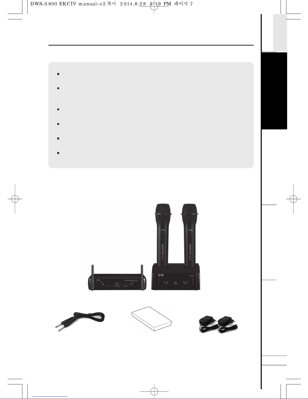
The world first 5.8 GHz digital wireless microphone
Support maximum 85 channels (1 Channel = 2 Microphones),
170 microphones at the same time
Best vocal microphone of 24bit & 96KHz sample rate
Luxury & solid high glossy design
Easy pairing between transmitterand receiver
Easy channel setting of transmitter via charging cradle
Microphone cable Manual 12V, 1.5A Adaptor(2 EA)
Transmitter (2 PCS)
Charging cradleReceiver
DWS-5800 Features
Accessories
7
E
T
C
.
S
A
F
E
T
Y
ENGLISH
S
Y
S
T
E
M
S
E
T
T
I
N
G
C
O
N
N
E
C
T
I
O
N
7

1 Antenna
2 Pairing switch for MIC1
3 Indicator for sync MIC1
4 MODE
5 Display screen
6 Selector
7 Indicator for sync MIC2
8 Pairing switch for MIC2
9 antenna
*For more detail of operating, please refer to “SYSTEM SETTING”.
External antenna for MIC1
Tact switch for pairing MIC1
MIC1 Light for connection, blinking on request MIC1 pairing
Multi-purpose button : While in pairing process
Indicator for group and channel
Change channel and group using ‘+’ and ‘-’.
MIC2 Light for connection, blinking on request MIC2 pairing
Tact switch for pairing MIC2
External antenna for MIC2
Receiver operation manual (front)
82
1 9
2 83 4 5 6 7
8

1 VOL 2
2 MIC 2
3 MIX
4 MIC 1
5 VOL 1
6 DC12V 1.5A
7 POWER ON/OFF
Adjust output volume for MIC2.
- Recommend to set the knob to 12’o clock direction(Center).
- MIC 2 sound could be distorted when adjusting the volume
of VOL2 according to input sensitivity of MIC preamp.
- Please adjust VOL2 adequately not to be distorted.
¼Jack output connector for MIC2.
¼Jack output signal connector for MIC1 and MIC2.
If the input gain from MIC preamp is not loud enough,
please adjust MIX knob.
¼Jack output connector for MIC1.
Adjust output volume for MIC1.
- Recommend to set the knob to 12’o clock direction(Center).
- MIC 1 sound could be distorted when adjusting the volume
of VOL1 according to input sensitivity of MIC preamp.
- Please adjust VOL1 adequately not to be distorted.
DC adaptor connector. (DC12V 1.5A only)
Power on/off switch for receiver.
Receiver operation manual (back)
212 3 4 5 6 7
VOL 2VOL 2 MIC 2MIC 2 MIXMIX MIC 1MIC 1 VOL 1VOL 1 DC12V 1.5ADC12V 1.5A POWERPOWER
MINMIN MAXMAX MINMIN MAXMAX
ONON
OFFOFF
S
A
F
E
T
Y
E
T
C
.
C
O
N
N
E
C
T
I
O
N
ENGLISH
S
Y
S
T
E
M
S
E
T
T
I
N
G
9

1 MIC ball
2 Lamp
*For more detail in power switch, please refer to ‘SYSTEM SETTING’ page.
MIC cartridge protector
Indicate status, control and alerting of transmitter.
3 Power switch Pairing and on/off power switch for transmitter.
Indication of Lamp LED Status Indication of
Transmitter Status
Yellow LED blinks for a second and off.
→
Green LED blinks every 4 second. Unpaired.
Yellow LED blinks for a second and off. Transmitter is turned off.
Red LED is on.
Warning indicator of
low battery.
(just before power
shut down)
Red LED blinks. MIC is on during
charging battery.
Yellow
→
Green LED blinks.
(every 2sec/10 times)
→
Red LED is on.
Low battery indicator.
Microphone(Transmitter) operation manual
1
2
3
DWS-5800T
10

Charging and paring cradle for MIC1 transmitter.
Charging and paring cradle for MIC2 transmitter.
Red light is on during charging MIC 1 (transmitter).
Green light on MIC1 indicates battery fully charged.
If the pairing switch on the bottom of the charging cradle
is selected to “pairing mode”, the white light will be on.
Red light is on during charging MIC 2 (transmitter).
Green light on MIC2 indicates battery fully charged.
*For more detail of pairing through chargingcradle, please refer to “How to pair with charging cradle”.
1 Cradle of MIC1 transmitter
2 Cradle of MIC2 transmitter
3 Charging indication light of MIC1
4 Fully charged indication light of MIC1
5 Pairing light
6 Charging Indication light of MIC2
7 Fully charged indication light of MIC2
- Pairing Mode : Pairing channels between the
transmitter and the charging cradle.
(Only for when in installation)
- Charger mode : For charging the transmitter.
1 Adaptor connector
2 Mode Switch
3 Cable guide for adaptor
Charging cradle operation manual (front)
Charging cradle operation manual (bottom)
21 2
3 4 6 75
1
2
3
Please switch off when charging the transmitter (MIC).
If the transmitter is on, green LED blinks quickly and repeatedly for caution.
Caution
S
A
F
E
T
Y
E
T
C
.
C
O
N
N
E
C
T
I
O
N
ENGLISH
S
Y
S
T
E
M
S
E
T
T
I
N
G
11
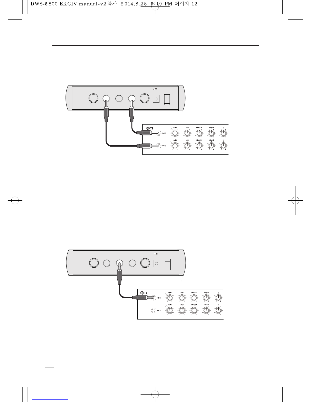
Connection with effector or powered mixer amplifier
Connection of microphones with ‘Mix’ output
Connecting with MIC input of powered mixer amplifier or effector.
‘Mix’ output makes it possible for the outputs of individual 2microphones to be mixed in 1 output.
So, even if there is only one microphone input in your mixer, amplifieror karaoke machine,
you can use 2 microphones at the same time using ‘Mix’ output of DWS-5800.
VOL 2VOL 2 MIC 2MIC 2 MIXMIX MIC 1MIC 1 VOL 1VOL 1 DC12V 1.5ADC12V 1.5A POWERPOWER
MINMIN MAXMAX MINMIN MAXMAX
ONON
OFFOFF
¼ Jack
Individual connection of microphone(s)
Connecting with MIC input of powered mixer amplifier or effector.
VOL 2VOL 2 MIC 2MIC 2 MIXMIX MIC 1MIC 1 VOL 1VOL 1 DC12V 1.5ADC12V 1.5A POWERPOWER
MINMIN MAXMAX MINMIN MAXMAX
ONON
OFFOFF
¼ Jack
¼ Jack
12

Installation of charging cradle mount
The charging cradle mount has a separable bracket toinstall to a wall.
Please refer to the following instruction when installing toa wall.
STEP1
Screw up the separable bracket (4 Points).
STEP2
Charging cradle mount set in bracket as following the picture.
2
1
1
1
1
S
A
F
E
T
Y
E
T
C
.
C
O
N
N
E
C
T
I
O
N
ENGLISH
S
Y
S
T
E
M
S
E
T
T
I
N
G
13

System setting
(Setting group, channel)
DWS-5800 wireless microphone can simply set channel and easily pair between
transmitters and a receiver.
DWS-5800 supports from 01CH ~ 99CH through a combination of group and channel.
(But the maximum supported channels are85 channels due to 14 non-allocated channels)
1. ‘MODE’ Button
: When you press the ‘MODE’, CHANNELdisplay panel will blink.
8
8
8
8828
82
2. ‘SELETOR’ -, + Button
: Use ‘SELECTOR - +’ to set the CHANNEL.
8
8828
82
3. ‘MODE’ Button
: After select the channel and press ‘MODE’, again. GROUP display panel will blink.
Then, you can set ‘GROUP’ in the sameway with channel setting.
2
8
82
8
82
4. ‘SELETOR’ -, + Button
: Use ‘SELECTOR - +’ to set the GROUP.
2
8
82
8
82
14

System setting
(How to pair : With receiver
→
MIC 1 pairing)
Please keep the distance within 50cm between receiver and microphone when pairing.
1 receiver supports 2 microphones, please finish the pairing of two microphones.
1. ‘MODE’ Button
: CHANNEL display blinks when pressing ‘MODE’ button.
00
0820
82
0820
2. ‘MIC 1’ Button
: When press ‘MIC 1’ button, indicator for sync MIC 1 will blink.
Which means MIC1 and Receiver are readyfor pairing.
3. ‘MIC 1’ Switch ON
: When the green LED is on, the pairing succeeds.
*If the pairing fails, the red RED will be on.
00
82
00
DWS-5800T
S
A
F
E
T
Y
E
T
C
.
S
Y
S
T
E
M
S
E
T
T
I
N
G
ENGLISH
C
O
N
N
E
C
T
I
O
N
15

System setting
(How to pair : With receiver
→
MIC 2 pairing)
Please keep the distance within 50cm between receiver and microphone when pairing.
1 receiver supports 2 microphones, please finish the pairing of two microphones.
1. ‘MODE’ Button
: CHANNEL display blinks when pressing ‘MODE’ button.
00
0
8
8
0820
82
0820
2. ‘MIC 2’ Button
: When press ‘MIC 2’ button, indicator for sync MIC 2 will blink.
Which means MIC2 and receiver are ready for pairing.
3. ‘MIC 2’ Switch ON
: When the green LED is on, the pairing succeeds.
*If the pairing fails, the red LED will be on.
82
00
82
00
DWS-5800T
16

System setting
(How to pair : With chargingcradle)
- It is also possible to pair between ‘Charging cradle’ and microphone(transmitter).
When the receiver is installed in cabinet or invisible place, you can easily pair with the charging
cradle.
- Please carefully read the below steps before installation.
The pairing with the charging cradle should be done only once at the initial installation.
But if a channel of the receiver and transmitters are changed, the channel of the charging
cradle should be synchronized with the changed channel of the receiver and transmitters.
Please select “pairing mode” on the bottom of charging cradle.
: White LED will be on, which means the charging cradle is ready to receive the channel from the receiver.
Step 1 : Transmit the channel of MIC(transmitter) to charging cradle
1
Please put the MIC1 which is already paired with receiver on the
charging cradle.
2
Turn on the MIC1
: When the MIC1 is on, the channel of MIC1 starts to be transmitted
to the charging cradle.
If the pairing is successful, the red LED and the green LED on MIC1
will blink consecutively and the white LED at the front of charging cradle
will blink as well.
4
After pairing, please select ‘charger mode’ on the bottom of the charging
cradle for normal use.
5
3
DWS-5800T
1
1
4
3
4
S
A
F
E
T
Y
E
T
C
.
S
Y
S
T
E
M
S
E
T
T
I
N
G
ENGLISH
C
O
N
N
E
C
T
I
O
N
17

18
System setting
(How to pair : With charging cradle)
This step is for when transmitter is replaced.
It is possible to simply pair for new transmitter using the charging cradle.
Step 2 : How to pair with charging cradle
Two microphones(transmitters) must be put on the charging cradle in order to transmit
the channel of charging cradle to the microphones(transmitters).
1
Turn on the transmitters on the charging cradle at the same time.
: green and red LED will blink subsequently when turn on the transmitter,
channel of charging cradle will be sent to transmitter automatically.
2
After the pairing, please turn off the microphones for charging.
3
Please turn off the microphones(transmitters) before charging.
If microphones(transmitters) are put on the charging cradle with turning on,
the green LED will blink.
Caution
DWS-5800T
DWS-5800T

Specification
SYSTEM
Working range line of sight
Operating channels
Audio sampling
Latency (delay)
Dynamic range
Total harmonic distortion
Operating temperature range
Up to 15m
85 channels
24Bit / 96kHz
3.4msecless
100dB, A-weighted
0.3% less, A-weighted, typical (Ref. 1KHz,100mV/rms)
0°C~+50°C
TRANSMITTER (MICROPHONE)
Working range line of sight
RF frequency band
Transmit power
Operating life time
Power consumption
Power supply
Dimensions (H ×W × D)mm
Weight
Up to 15m
5.7275 to 5.820875 GHz
10mW less
Up to 10 Hours (one time charge)
820mW
Li-ion 3.7V / 2,200mA
250 × ট40 (Mic Ball ট52)
284g (with battery)
RECEIVER
RF frequency band
Transmit power
Audio output connectors
Configuration
Power consumption
Power supply
Dimensions (W × H × D)mm
Weight
5.7275 to 5.820875 GHz
10mW less
¼” Phone Jack × 2, Mixer ¼” Jack × 1
Impedance Unbalanced
2.64W
Adaptor(SMPS) DC12V / 1.5A
208(W) × 45(H) × 110(D)
306g
CHARGER
Power supply
Dimensions (W × H × D)mm
Weight
Adaptor(SMPS) DC12V / 1.5A
152.5(W) × 75.5(H) × 81.5(D)
258g
S
A
F
E
T
Y
E
T
C
.
ENGLISH
C
O
N
N
E
C
T
I
O
N
S
Y
S
T
E
M
S
E
T
T
I
N
G
19

본제품은 대한민국용으로 제작, 판매되는 제품으로 타국가 판매 시발생되는 전파, 품질 문제에 대해서는 TJ미디어는
책임을 지지 않습니다.
무선 제품으로 국가별 전파 규격에 영향을 받는 제품이기 때문에 대한민국 이외 국가에서 사용시 반드시 해당 국가의 전파 승인을
득하시기 바랍니다.
법에 의해 전방향 전파발사 및동일한 정보를 동시에 여러 곳으로 송신하는 점-대-다지점 서비스에의 사용은 금지되어 있습니다.
사용전에 안전을 위한 주의사항을 반드시 읽고 정확하게 사용해 주세요.
사용설명서에 제품보증서가 포함되어 있습니다.
제품의 성능을 충분히 활용할 수있도록 사용설명서를 처음부터 끝까지 잘읽어 주세요.
다읽으신 후에도 필요하실 때에 볼수있는 장소에 보관해 주세요.
본제품은 전자파 장해 검정을 받은 기기로서 업소용으로 사용할 수있습니다.
DWS-5800 사 용 설 명 서
5.8GHz DIGITAL WIRELESS MICROPHONE SYSTEM
한국어
Table of contents
Languages:


