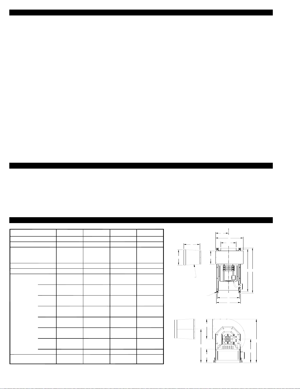
TJERNLUND AUTO-DRAFT VSUB Series User manual

Copyright © 2004, Tjernlund Products, Inc. All rights reserved. P/N 8504114
REV. 02/04
THESE INSTRUCTIONS ARE INTENDED AS AN AID TO QUALIFIED, LICENSED
SERVICE PERSONNEL FOR PROPER INSTALLATION, ADJUSTMENT AND
OPERATION OF THIS UNIT. READ THESE INSTRUCTIONS THOROUGHLY
BEFORE ATTEMPTING INSTALLATION OR OPERATION. FAILURE TO FOLLOW
THESE INSTRUCTIONS MAY RESULT IN IMPROPER INSTALLATION, ADJUST-
MENT, SERVICE OR MAINTENANCE POSSIBLY RESULTING IN FIRE, ELECTRI-
CAL SHOCK, CARBON MONOXIDE POISONING, EXPLOSION, PERSONAL
INJURY OR PROPERTY DAMAGE.
DO NOT DESTROY. PLEASE READ CAREFULLY AND KEEP IN
A SAFE PLACE ON JOB SITE FOR FUTURE REFERENCE.
MODELS
VSUB8
VSUB12
VSUB16
VSUB20
AUTO-DRAFT®VSUB-SERIES
VSUB BLOWERS
For providing combustion air; sidewall or
vertically venting heating appliances, dryers
and ovens. Can be installed indoors or
outdoors.
TJERNLUND PRODUCTS, INC.
1601 Ninth Street • White Bear Lake, MN 55110-6794
PHONE (800) 255-4208 • (651) 426-2993 • FAX (651) 426-9547
Visit our web site • www.tjernlund.com
Listings:
ETL CERTIFIED TO:
UL 378 - Draft Equipment / Variable Speed
UL 705 - Power Ventilators
CSA-CAN3-B255-M81
RECOGNIZE THIS SYMBOLAS AN INDICATION OF IMPORTANT SAFETY INFORMATION!
!

TABLE OF CONTENTS
PAGE(S)
VSUB BLOWER DESCRIPTION ................................................................................................................................. 1
DIMENSIONS AND SPECIFICATIONS ........................................................................................................................ 1
VSUB FAN PERFORMANCE CURVES..........................................................................................................................2
INSTALLATION RESTRICTIONS & CAUTIONS ........................................................................................................... 3
ADDITIONAL REQUIREMENTS BASED ON DRAFT INDUCER OR COMBUSTION AIR APPLICATION............... 3-4
DRAFT INDUCER TERMINATION CLEARANCES FOR CANADIAN & U.S. INSTALLATIONS ............................... 4-6
COMBUSTION AIR INTAKE CLEARANCES ................................................................................................................ 6
COMBUSTION AIR INTAKE HOOD/LOUVER OPENING SIZING............................................................................. 6-7
VSUB INSTALLATION ............................................................................................................................................... 7-8
PSA-1 FAN PROVING SWITCH INSTALLATION ...................................................................................................... 8-9
WIRING .....................................................................................................................................................................9-11
PSA-1 SAFETY INTERLOCK AND DRAFT ADJUSTMENT SET-UP PROCEDURE..............................................12-13
SAFETY INTERLOCK TEST.........................................................................................................................................13
COMBUSTION AIR ...................................................................................................................................................... 13
MAINTENANCE, SERVICE & HOUSING ROTATION.............................................................................................13-14
HOW TO OBTAIN SERVICE & LIMITED WARRANTY ..........................................................................................14-15
REPLACEMENT PARTS ..............................................................................................................................................15
Tjernlund Products welcomes your comments and questions. Call us at 800-255-4208, Fax 651-426-9547, Email us at
[email protected] or write to: Customer Service, Tjernlund Products, Inc., 1601 Ninth Street, White Bear Lake, MN 55110-6794.
VSUB-SERIES UNIVERSAL BLOWER DESCRIPTION
The VSUB-Series Universal Blowers are a multi-purpose adjustable-fixed speed or automatic-variable speed blower. It can vent natur-
al gas, LP-gas and oil fired heating appliances, clothes dryers or be used as a utility blower that will handle up to 575° F. It can also
be used as a adjustable-fixed speed or as an automatic-variable speed combustion air intake blower. All models are supplied with the
model PSA-1 Fan Proving Switch which will disable the burner(s) if an exhaust/supply malfunction should occur, and a FFP-1 fire
/freeze limit that will shut the VSUB Blower off in the event of extreme temperature swings for combustion air applications. The VSUB
Blower is rated for indoor or outdoor installation. Use positive pressure rated vent on the discharge side of the blower when venting
flue gases and mounting indoors. Refer to heating appliance manufacturer's instructions regarding specific venting requirements.
DIMENSIONS AND SPECIFICATIONS
1
3x230/460
2875
1.6
66
7 7/8
5 1/4
16 1/2
28 1/2
14 1/2
10 1/4
2125
3.2
153
11 7/8
9 5/8
21 1/2
33
17 3/8
13
2115
6.0
218
15 7/8
12
27 3/4
42 3/8
23 1/4
16
1760
8.8
319
19 7/8
14 1/2
32 3/4
44 3/4
26 1/2
23 1/4
Yes with
VFD
VSUB8 VSUB12 VSUB16 VSUB20
Does not include Amp load of VFD Drive.
in
in
in
in
in
in
lbs
@ 208 V
VAC
A
C
E
G
I
K
Dimensions
Weight
Full Speed
Max RPM with VFD
Voltage
MODEL
Variable Speed Motor
Figure 8067001 3/3/04
Power Rating hp 1/3 1 32
L
J
H
in 18 1/2
in
in
15 1/2
30 1/2
22
35
18 7/8
F
D
B
in
in
7 7/8
7 5/8
in 10
10
11 7/8
12 1/2
25 1/2
28
46 3/4
26 3/4
24 3/4
44 3/8
14
14
19 3/415 7/8
13 1/4
14
M
O
N
8in
in
in 23 1/2
13 3/8 9
28 1/2
15 1/2 19
43 3/4
23 1/2
15 3/8
34 3/4
18 7/8
3x230/460 3x230/460 3x230/460
@ 460 V 0.8 1.5 2.8 4.1
Yes with
VFD
Yes with
VFD
Yes with
VFD
5.6
@ 230 V 1.5 3.0 8.2
Amps *
*
O
L
END VIEW
M
N
K
MOUNTING
LOCATION (4)
D
TOP VIEW
B
ØA
ØF
E
C
GH
I
J
INCLUDED SQUARE
TO ROUND ADAPTER

COMPLETE VSUB-SERIES UNIVERSAL BLOWER SYSTEM SOLUTIONS
This installation manual does not contain any vent system design documentation. Installation and use of Tjernlund controls like the
CPC-2 Constant Pressure Controller, VFD Series Variable Frequency Drives, EXP-4 Appliance Interlock Expansion boards, UC-1
Universal Control or MAC1E and MAC4E Multiple Appliance Controls are not covered by this manual. Please refer to those installa-
tion manuals for details.
VSUB-SERIES FAN PERFORMANCE CURVES
VSUB Blower performance was independently tested by an accredited AMCA certified testing facility.
Selection of a VSUB Blower as a Draft Inducer involves determination of the maximum volume of gas to be handled, the density of
the gas and the maximum static pressure which the fan must overcome. Using the VSUB Blower as a combustion air intake or com-
mercial clothes dryer vent blower, involves the determination of the maximum volume of air to be handled and the maximum static
pressure which the fan must overcome.
Variable speed VSUB Blowers can operate at virtually any point to the left of the performance curve. For sidewall termination applica-
tions add 0.60" W.C. to vent system resistance to accommodate the effects of wind loading.
Consideration must be given to the temperature of the gases being handled and the elevation above sea level of the installation when
selecting a VSUB Blower. Blower performance curves are based on standard air conditions @ sea level.
Please feel free to contact us for application and model selection assistance by calling 800-255-4208 or email us at
2
00
CFM (STD AIR 70 DEGREES F)
STATIC PRESSURE IN W.C.
0
0
100 200 300 400 500 600 700 800 900 1000
1000900800700600500400300200100
0.5
1
1.5
2
2.5
3
3.5
4 4
3.5
3
2.5
2
1.5
1
0.5
VSUB8 PERFORMANCE
3
2.5
2
1.5
1
0.5
00 500 1000 1500 2000 2500
CFM (STD AIR 70 DEGREES F)
STATIC PRESSURE IN W.C.
0
0
0.5
1
1.5
2
2.5
3
VSUB12 PERFORMANCE
2500200015001000500
4.5
4
3.5
3
2.5
2
1.5
1
0.5
00 500 1000 1500 2000 2500 3000 3500 4000 4500
CFM (STD AIR 70 DEGREES F)
STATIC PRESSURE IN W.C.
0
0
0.5
1
1.5
2
2.5
3
3.5
4
4.5
45004000350030002500200015001000500
VSUB16 PERFORMANCE
4.5
4
3.5
3
2.5
2
1.5
1
0.5
00500 1000 1500 2000 2500 3000 3500 4000 4500 5000 5500 6000
CFM (STD AIR 70 DEGREES F)
STATIC PRESSURE IN W.C.
600055005000450040003500300025002000150010005000
0
0.5
1
1.5
2
2.5
3
3.5
4
4.5
VSUB20 PERFORMANCE

3
INSTALLATION RESTRICTIONS
Failure to install, maintain and/or operate the VSUB Blower in accordance with manufacturer's instructions may result in
conditions which can produce bodily injury and property damage.
The VSUB Blower must be installed by a qualified installer in accordance with these instructions and all local codes or in their
absence in accordance with the latest edition of The National Fuel Gas Code (NFPA 54), NFPA 211 or 31 when applicable, the latest
edition of the National Electrical Code (NFPA 70) and the Occupational Safety and Health Act (OSHA) when applicable. In the
absence of local codes in Canada, installations must comply with the Canadian Electrical Code (CSA Std 22.1), the latest edition of
the Natural Gas Installation Code (CAN/CGA-B149.1), the Propane Installation Code (CAN/CGA-B149.2) and the Installation Code for
Oil Burning Equipment (CSA Std B139-M91).
Improper installation can create a hazardous condition such as an explosion, fire, electrical shock or carbon monoxide poisoning
resulting in property damage, personal injury or death.
1. The VSUB Blower is intended to be installed on natural gas, LP-gas or oil-fired heating appliance systems. The VSUB Blower is
not Listed for use on condensing equipment in Canada.
2. The VSUB Blower was tested with exit flue gas temperatures of 575OF (300OC).
3. The VSUB Blower may not be installed on incinerators, incinerating toilets or solid-fuel burning appliances.
4. The VSUB Blower shall not be installed on an appliance with an automatic valve having a manual opener unless the manual
opener has been rendered inoperative or the automatic valve has been replaced with a valve not equipped with a manual opener.
5. VSUB Blowers not utilizing the Tjernlund CPC-2 Constant Pressure Control may only be installed on appliances equipped
with a draft hood, draft diverter or barometric draft control.
6. Tjernlund’s Model FFP-1, Fire and Freeze Protection Limit must be installed when using the VSUB as a combustion air intake to
protect the boiler room from temperature extremes. Do not install FFP-1 when VSUB is used as a draft inducer. It is designed to
disrupt power to a combustion air supply blower in the event of a boiler room fire or an extended period where frigid outdoor air
supply could cause pipes to freeze.
D
Never operate a mechanical draft or combustion air system without a proving device that proves the flow of flue gasses or combustion
air and is interlocked with all of the heating appliances. If installing a VSUB Blower in conjunction with a CPC-2 controller, the CPC-2
provides the safety interlock. If installing a VSUB Blower without a CPC-2 controller the PSA-1 fan proving switch must be installed in
conjunction with a UC1 Universal interlock control and any additional MAC-Series multiple appliance controls necessary to interlock
all heaters being vented.
IONS INSTALLER CAUTIONS
Disconnect the power supply when making wiring connections or when working around the fan impeller and motor. Failure
to do so can result in electrical shock, personal injury, death or property damage.
1. The VSUB Blower must be interlocked with the heating appliance burner(s).
2. Plan the vent system so that the code required clearances are maintained from plumbing, wiring and combustibles.
3. Make certain the power supply is adequate for VSUB Blower motor and VFD requirements. Do not add the VSUB Blower to a
circuit where the total load is unknown.
4. The installer must verify that the appliance on which the VSUB Blower will be installed is in a safe operating condition.
Consult appliance manufacturer’s Instructions for details.
5. VSUB Blower housing is single wall. Standard clearances to combustibles must be maintained when venting flue products.
6. VSUB Blowers must use the appropriate Tjernlund VFD model.
REQUIREMENTS WHEN USING THE VSUB BLOWER FOR COMBUSTION AIR INTAKE
Unless properly screened or guarded to prohibit contact with the blower wheel, a minimum of 3' of pipe must be connected to the
inlet/discharge of the VSUB Blower.
Use the FFP-1, Fire and Freeze Protection Limit that was provided in the VSUB Blower. Place this limit in the physical location as
defined in the limit installation instructions and wire into the control circuit as recommended for your type of installation. This limit is
designed to shut off the combustion air supply if excessive heat or extremely cold air is present in the mechanical room. Do not mount
the limit next to hot or cold surfaces or in the flow of the blower discharge.
1. Make sure the VSUB specified is large enough to supply the combustion air for all heating appliances in the mechanical room.
Tjernlund Products, Inc. is not responsible for vent layout, appliance type, size or design changes to the air supply system. The
Mechanical room must be sealed to keep the supplied air from being bypassed to other parts of the building or outdoors. We rec-
ommend that the blower be oversized by 25% to accommodate any unforeseen leakage.

4
2. If possible, discharge the air at or towards ceiling levels to mix the supply air with the warmer stratified mechanical room air.
Consideration should be given to the use of ducts and diffusers to evenly distribute the air throughout the mechanical room. NOTE:
Do not discharge air directly across water lines, temperature control devices, or draft hoods/draft controls. If correctly installed no
additional air heating means will be required beyond what heating means would be required for conventional air supply louvers.
3. Give careful consideration to the air inlet opening as it enters the building to connect to the supply duct system. Too high of a cap-
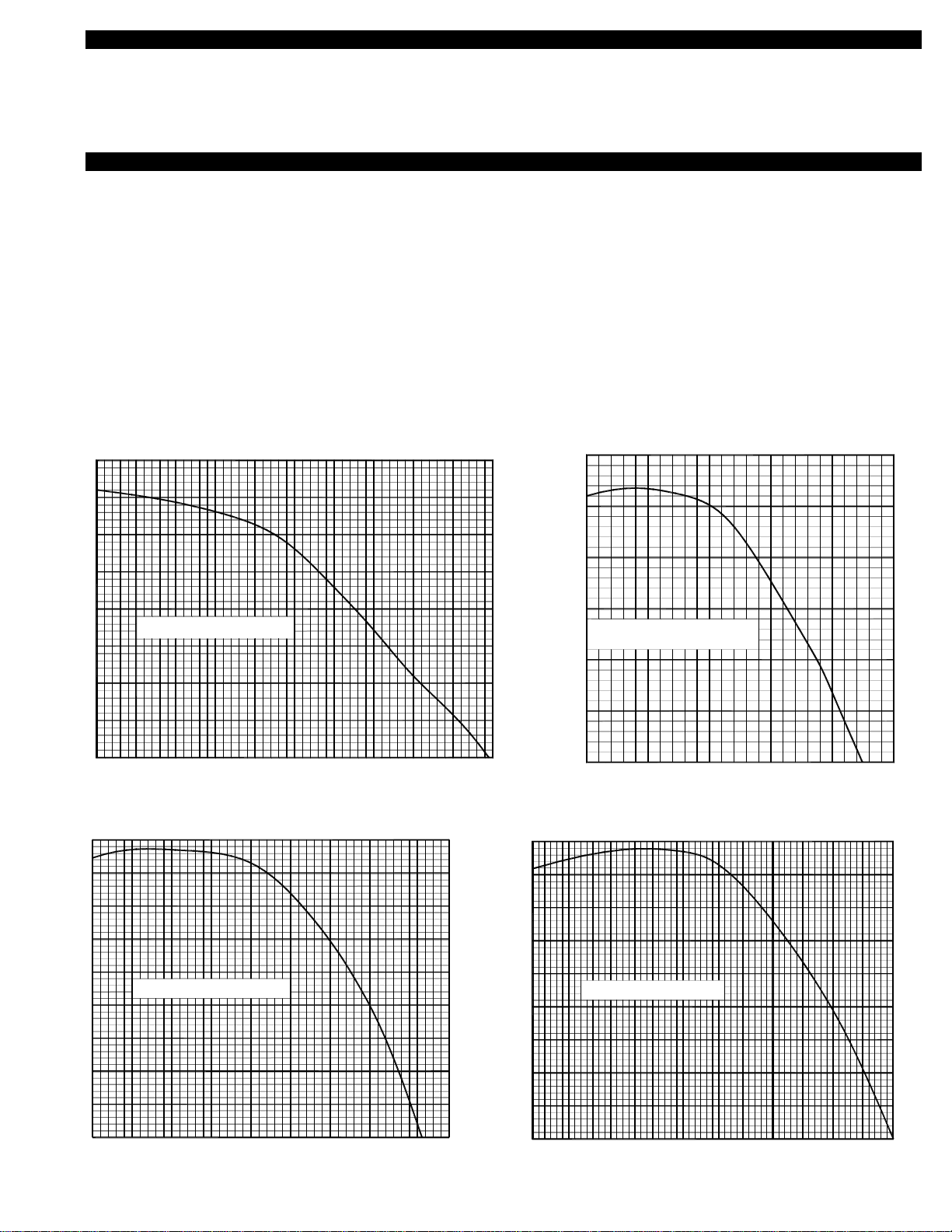
ture velocity can entrain rain or snow into the mechanical room. We recommend a capture velocity no greater than 800 feet per
minute for rain and 650 feet per minute for snow. Capture velocity is calculated by dividing the maximum Cubic Feet per Minute
(CFM) of air by the Square Feet of area it is pulled through. 1000 CFM through a 1' x 2' opening, would have a capture velocity of
500' per minute. Note: Inlet screens and louvers are typically not fully open and have an open area percentage. Make sure to add
area to the air opening to compensate for the reduction caused by the screen and/or louver blade.
4. The inlet shape has a bearing on the entrainment and capture velocity of the incoming air. In general, long tapered openings are
preferred to short flat openings. Inlet screening will help spread the velocity more evenly across the air inlet opening.
5. If possible, use gravity to your advantage, rain and snow are harder to pull up than they are to pull sideways. Do not design an inlet
opening that points upwards.
6. Refer to the Industrial Ventilation Manual produced by the American Conference of Governmental Industrial Hygienist or the
ASHRAE Fundamentals handbook for more in depth information.
REQUIREMENTS WHEN USING THE VSUB BLOWER FOR MECHANICAL DRAFT
1. Make sure the VSUB Blower specified is large enough to remove the exhaust gasses for all the heating appliances connected to it.
Tjernlund Products, Inc. is not responsible for vent layout, appliance type or design changes to the heating system.
2. For Vertical discharges: The VSUB Blower housing can be rotated to facilitate a vertical discharge. Make sure the clearance to
combustible surfaces inside and outside the building are followed as discussed in your state and local codes or in their absence,
the National fuel gas code NFPA 211 and NFPA 54 or 31. Canadian installations must comply with local codes or in their absence,
the latest edition of the Natural Gas Installation Code (CAN/CGA-B149.1), the Propane Installation Code (CAN/CGA-B149.2) and
the Installation Code for Oil Burning Equipment (CSA Std B139-M91). The VSUB Blower is designed for variable speed applica-
tions and the discharge velocity from the outlet of the blower or vent system can be similar to a conventional chimney.
For Horizontal discharges: The VSUB Blower can be rotated if necessary to facilitate a horizontal discharge. Make sure the clear-
ance to combustible surfaces inside and outside the building are followed as discussed in your state and local codes or in their
absence, the National fuel gas code NFPA 211 and NFPA 54 or 31. Canadian installations must comply with local codes or in their
absence, the latest edition of the Natural Gas Installation Code (CAN/CGA-B149.1), the Propane Installation Code (CAN/CGA-B149.2)
and the Installation Code for Oil Burning Equipment (CSA Std B139-M91). In addition, we strongly recommend that an exhaust ter-
mination be developed that has an outlet opening at least 1.5 times the area of the outlet area of the VSUB being used. If the dis-
charge opening is screened, verify that the screen does not reduce the open area to less than that of the connected vent pipe. The
termination should not direct the flue gasses down the building exterior and should not face directly into wind. The VSUB is rated to
handle 575°F flue gases. Consider the application temperature when developing the termination.
Never operate a mechanical draft or combustion air system without a proving device that proves the flow of flue gasses and is inter-
locked with all of the heating appliances. If installing a VSUB Blower in conjunction with a CPC-2 controller, the CPC-2 provides the
safety interlock. If installing a VSUB Blower without a CPC-2 controller the PSA-1 fan proving switch must be installed in conjunction
with a UC1 Universal Control and any additional MAC-Series multiple appliance controls necessary to interlock all heaters being vented.
MECHANICAL DRAFT TERMINATION CLEARANCES FOR CANADIAN INSTALLATIONS
In the absence of local codes in Canada, installations must comply with the latest edition of the Natural Gas Installation Code
(CAN/CGA-B149.1), the Propane Installation Code (CAN/CGA-B149.2), the Installation Code for Oil Burning Equipment (CSA Std
B139-M91) or as follows, (See Diagram A).
• A venting system shall not terminate underneath a veranda, porch, or deck, or above a paved sidewalk or a paved driveway
that is located between two buildings, and that serves both buildings.
• The exit terminals of mechanical draft systems shall not be less than 2.13m (7ft) above grade when located adjacent to a paved
sidewalk or driveway.
• A venting system shall not direct flue gases towards brickwork, siding, or other construction, in such a manner that may cause
damage from heat or condensate from the flue gases.
• A venting system shall not direct flue gases so as to jeopardize people, overheat combustible structures, or enter buildings.
Aventing system shall not terminate within 1.8 m (6ft) of the following:
• A window, door or mechanical air supply inlet of any building, including soffit openings
• A gas service regulator vent outlet
• A combustion air inlet
• A property line
• A direction facing combustible materials or openings of surrounding buildings
Aventing system shall not terminate within 1m (3ft) of the following:
• Above a gas meter/regulator assembly within 1m (3ft) horizontally of the vertical centreline of the regulator
• A oil tank or an oil tankfill inlet
Aventing system shall not terminate within .3m (1ft) of the following:
• Above grade level or any surface that may support snow, ice, or debris

5
MECHANICAL DRAFT TERMINATION CLEARANCES FOR U.S. INSTALLATIONS
CODE REQUIREMENTS
Terminate the VSUB Blower so that proper minimum clearances are maintained as cited in the latest edition of the National Fuel Gas
Code (NFPA 54), NFPA 211 or 31 when applicable, (See Diagram B):
• Not be less than 7 feet above grade when located adjacent to public walk ways.
• At least 3 feet above any forced air inlet located within 10 feet.
• At least 4 feet below, 4 feet horizontally from or 1 foot above any door, window or gravity air inlet into any building.
• At least 1 foot above grade.
• So that the flue gases are not directed so as to jeopardize people, overheat combustible structures or enter buildings, and
• Not less than 2 feet from an adjacent building.
DIAGRAM A CANADA

6
INTAKE HOOD/LOUVER LOCATIONS WHEN USING THE VSUB BLOWER AS A COMBUSTION AIR INTAKE
The VSUB Intake Hood/Louver location must
conform with the BOCA National Mechanical
Code or local codes.
LOCATION:
Outside air exhaust and intake openings shall
be located a minimum of 10 feet (3048mm)
from lot lines or buildings on the same lot.
When openings front on a street or public way,
the distance shall be measured to the center-
line of the street or public way.
INTAKE OPENINGS:
Outside air intake openings shall be located a
minimum of 10 feet (3048mm) from any hazard
or noxious contaminant such as vents, chim-
neys, plumbing vents, streets, alleys, parking
lots and loading docks. When a source conta-
minant is located within 10 feet (3048mm) of an
intake opening, such opening shall be located a
minimum of 2 feet (610mm) below the contami-
nant source.
IN ADDITION TO THESE CODES THE
MANUFACTURER RECOMMENDS THAT:
The Intake Hood/Louver should be a minimum of
1 foot above grade or anticipated snow line.
INTAKE HOOD/LOUVER SIZING WHEN USING THE VSUB BLOWER AS A COMBUSTION AIR INTAKE
When sizing an intake opening for northern climates always use 650'/min as a maximum capture velocity with respect to outside air
being entrained to an inside environment. For southern applications where snow is infrequent, 800 '/min can be used in respect to rain.
DIAGRAM B UNITED STATES
On wall installations, if possible, terminate the Intake Hood/Louver on a wall that does not face the
direction of prevailing winds. This will diminish the possibility of wind infiltration.

7
1000 CFM will require a minimum 15" x 15" opening to have a maximum capture velocity of 650'/min.
If an intake grille is 75% open, the area will need to increase to 17.25" x 17.25" to maintain a design maximum velocity of 650'/min.
2000 CFM will require a minimum 21" x 21" opening to have a maximum capture velocity of 650'/min.
If an intake grille is 75% open, the area will need to increase to 24.25 " x 24.25" to maintain the design maximum velocity of 650'/min.
4000 CFM will require a minimum 30" x 30" opening to have a maximum capture velocity of 650'/min.
If an intake grille is 75% open, the area will need to increase to 34.25" x 34.25" to maintain the design maximum velocity of 650"/min.
6000 CFM will require a minimum 36.5" x 36.5" opening to have a maximum capture velocity of 650'/min.
If an intake grille is 75% open, the area will need to increase to 42" x 42" to maintain the design maximum velocity of 650'/min.
INSTALLATION OF THE VSUB BLOWER
The VSUB Blower is designed to fit any type of industry standard 8", 12", 16" or 20" diameter vent pipe. Vent pipe must be installed
and supported according to manufacturer’s instructions, local codes and/or in accordance with NFPA 211, "Chimneys and Vents". The
VSUB Blower is rated for indoor or outdoor installation. Factory insulated vent pipe may reduce clearances to combustibles when pen-
etrating a combustible roof or wall. Refer to vent pipe manufacturer’s instructions for details.
Unless properly screened or guarded to prohibit contact with the blower wheel, a minimum of 3 feet of pipe must be connected to the
inlet/discharge of the VSUB Blower.
Do not use the VSUB Blower inlet or outlet collars to support the vent pipe. Support the vent pipe as instructed by the vent pipe man-
ufacturer.
The VSUB Blower housing can rotate 180 degrees in 45° increments, see “Housing Rotation”, Page 13. Always mount the VSUB
Blower so the shaft of the motor is horizontal and base is pointing down.
INSTALLING VSUB BLOWERS OUTDOORS WHEN USED AS A MECHANICAL DRAFT INDUCER
When installing VSUB Blowers outdoors as a mechanical exhauster, never orient the discharge vertically without installing a rain cap
or a vent pipe that alters the discharge to horizontal. Rain caps must be raised a distance equal to the vent diameter above the VSUB
Blower outlet. A minimum of 3 diameters of straight vent must be installed prior to connecting any elbow. Never connect a 90° elbow
directly to the discharge.
INSTALLING CONDENSATE DRAIN
IMPORTANT:
If the the VSUB Blower is mounted outdoors or potentially subject to condensation, we recommend the
use of the supplied condensate drain. Make sure to mount the condensate drain into the lowest point of
the VSUB Blower housing.
1. Use mounting plate as template and a drill bit for stainless steel to drill (4) 5/32" holes and (1) 1/2"
hole into lowest point of VSUB Blower housing, (See Diagram C)
2. Use supplied mounting screws to fasten mounting plate to the bottom of housing. Seal connection
with RTV sealant.
3. Connect to 3/8” NPT fitting and route drain to appropriate location.
MOUNTING FROM CEILING
1. Make sure the overhead support will handle 4 times the static weight of the Universal
Blower being installed, See “Specifications” on page 1.
2. To help prevent the VSUB Blower from swinging while operating we recommend mount-
ing the supports at a 30° angle, (See Diagram D).
3. Use either the provided eyebolts or 3/8" rod to suspend the VSUB Blower from overhead.
4. Make sure the VSUB Blower is mounted level and plumb. If necessary, rotate the housing
only for desired discharge angle, see “To Rotate Housing”, Page 14. Keep motor shaft parallel
with floor/roof and mounting base pointed down.
MOUNTING ON ROOF
1. Make sure the roof surface you plan to mount the VSUB Blower on is level.
2. When mounting on a roof we recommend using rooftop mounting support rails.
3. Make sure roof top mounting support rails are rated to handle the weight of the VSUB Blower, See “Specifications” on page 1.
4. Install vibration isolation pads between rooftop support rail and VSUB Blower base.
5. After positioning VSUB Blower remove the four eyebolts from the base and secure blower to roof rail with lag screws.
DIAGRAM C
MOUNT WITH SUPPORTS AT A 30O
ANGLE TO PREVENT UNIT FROM
SWINGING.
DIAGRAM D
MOUNT AT LOWEST POINT IN
VSUB HOUSING.

8
MOUNTING ON FLOOR
1. Make sure the surface you plan to mount the VSUB Blower on is level.
2. When mounting on the floor we recommend using anti-vibration floor mounts, springs or pads.
3. Make sure anti-vibration floor mounts, springs or pads are rated to handle the weight of the
VSUB Blower you are installing.
4. Fasten the floor mount, springs or pads to the bottom frame of the VSUB Blower.
5. Secure the VSUB Blower to the floor to ensure that is doesn't move during operation.
PSA-1 FAN PROVING SWITCH FOR ADJUSTABLE-FIXED SPEED MECHANICAL DRAFT INDUCER INSTALLATIONS
The PSA-1 is a field adjustable pressure switch
that is the primary fan prover for VSUB Blowers
not installed in conjunction with a CPC-2 con-
troller, and the manual operation mode fan
prover for installations incorporating a CPC-2
controller.
1. Install Fan Proving Switch sampling tube in
the vent connector as close as possible to
VSUB inlet and 2-3 pipe diameters away from
any elbow or “T”. For multiple appliances vent-
ing into a common manifold, install after appli-
ance closest to the VSUB Blower. If the
vent run is completely vertical, install after
draft hood or barometric damper, (See
Diagram E).
2. Drill 1/4" hole for Fan Proving Switch sampling
tube. The hole should be burr free. Secure
sampling tube bracket to pipe with sampling
hole centered.
3. Insert stainless steel sampling tube through
1/4" hole enough to just penetrate interior of
vent pipe and lock in place with compression
nut, (See Diagram F). With the VSUB Blower
on, a negative pressure reading on a draft
gauge is an indication that the interior of the
pipe has been penetrated.
4. Fan Proving Switch diaphragm must be mounted in a VERTICAL position within six feet of the sensing location. Firmly insert flexi-
ble tubing on sampling tube and Fan Proving Switch fitting marked (LOW). Leave the other Fan Proving Switch port open to room
atmosphere for reference. Make sure there are no sharp bends or kinks in flexible tubing. Do not mount the PSA-1 so that is direct-
ly in the path of the VSUB Blower discharge, unit heater or duct discharges. Doing so may cause a false reference pressure read-
ing, (See Diagram G).
PSA-1 FAN PROVING SWITCH FOR ADJUSTABLE-FIXED SPEED COMBUSTION AIR INTAKE INSTALLATIONS
The PSA-1 is a field adjustable pressure switch that is the primary fan prover for VSUB Blowers not
installed in conjunction with a CPC-2 controller, and the manual operation mode fan prover for installa-
tions incorporating a CPC-2 controller.
1 Install Fan Proving Switch sampling tube in the DISCHARGE/OUTLET duct as close as possible to
the outlet collar of the VSUB Blower. Directly after the VSUB Blower outlet collar the pressure will be
greatest at the point in line with the top of the scroll blower housing, (See Diagram H). If VSUB
Blower is mounted outside install sampling tube on closest indoor section of duct.
2 Drill 1/4" hole for Fan Proving Switch sampling tube. Insert sampling tube with 90° bend so that the
short side faces directly towards the VSUB discharge/outlet. Secure sampling tube bracket to pipe
with sampling hole centered. With all pipe connected, start VSUB Blower and adjust tube until a
high pressure reading is available, (at least +0.10” w.c.)
OR
VSUB-SERIES
IN VERTICAL OR
HORIZONTAL
TERMINATION
APPLIANCE
GAS APPLIANCE DRAFT
SAMPLE LOCATION
(MUST BE MOUNTED
SIX FEET OF SENSING
VERTICALLY WITHIN
FAN PROVING SWITCH
FIGURE CPE98 3/2/04
LOCATION)
FLAME RETENTION
OIL BURNERS
OVER-FIRE DRAFT
TJERNLUND ABD-SERIES
BALANCING BAFFLE
(IF BAFFLE IS INSTALLED
IT MUST BE POSITIONED
AFTER FAN PROVING SWITCH)
DRAFT CONTROL
/ DRAFT HOOD
DIAGRAM E
DIAGRAM F
1/4” STAINLESS STEEL
SAMPLING TUBE BEND MUST
FACE UPWARD
COMPRESSION FERRULE
COMPRESSION NUT
SAMPLING PORT CENTERED
OVER 1/4” HOLE
DIAGRAM G
FAN PROVING SWITCH MUST
BE MOUNTED WITHIN SIX
FEET OF SAMPLING TUBE.
SWITCH CAN BE ORIENTATED
IN A 360OPLANE AS LONG AS
DIAPHRAGM IS IN A VERTICAL
ORIENTATION AND TUBING IS
NOT KINKED.
FACE SAMPLING
TUBE INTO AIR
STREAM
DIAGRAM H

9
3. Lock in place with compression nut. With the VSUB Blower on, a positive pressure reading on a draft gauge is an indication that
the tube has been orientated properly.
4. Fan Proving Switch diaphragm must be mounted in a VERTICAL position within six feet of the sensing location. Firmly insert flexi-
ble tubing on sampling tube and Fan Proving Switch fitting marked (HIGH). Leave the other Fan Proving Switch port open to room
atmosphere for reference. Make sure there are no sharp bends or kinks in flexible tubing. Do not mount the PSA-1 so that is direct-
ly in the path of the VSUB Blower discharge, unit heater or duct discharges. Doing so may cause a false reference pressure reading.
WIRING
All wiring from the VSUB Blower to the appliance must be in compliance with local codes or in their absence, the National Electric
Code (NFPA 70).
All wiring from the VSUB Blower to the appliance must be appropriate class 1 wiring as follows: Installed in rigid metal conduit, inter-
mediate metal conduit, rigid non-metallic conduit, electrical metallic tubing, Type M1 cable or be otherwise suitably protected from
physical damage.
IMPORTANT:
All wiring from the VFD Variable Frequency Drive or CPC-2 constant Pressure Controller must be in metal conduit or shield-
ed cable where appropriate. Do not route these wires with any other wires. Improper system operation could result.
This installation manual does not contain any system design documentation. Installation and use of Tjernlund controls like the CPC-2
Constant Pressure controller, EXP-4 Appliance Interlock Expansion Boards, VFD-Series Variable Frequency Drives, UC1 Universal
Control, TD-2/TD-3 Pressure Transducer or MAC1E and MAC4E Multiple Appliance Controls are not covered by this manual. Please
refer to those accessory installation manuals.
WIRING VSUB MOTOR FOR PROPER VOLTAGE
IMPORTANT: CONFIRM PROPER IMPELLER ROTATION
If this VSUB Blower is being installed in conjunction with a CPC-2 Controller, follow impeller rotation check instructions outlined in the
CPC-2 installation instructions. Failure to insure correct rotation will result in higher power usage and poor blower performance.
All VSUB Blowers must use a Variable Frequency Drive (VFD) supplied by Tjernlund which is factory programmed specifically for the
VSUB model being installed.
VISUAL METHOD TO VERIFY PROPER ROTATION:
VSUB Series impeller must rotate counter-clockwise as viewed from the motor side, (See Diagram I). Verify motor cooling fan at back
of motor rotates counter-clockwise. While the VSUB Blower is running at a slow speed, starting up or coming to a stop, visually deter-
mine if the rotation is correct. Perform step 4 on page 10 if rotation is in the reverse direction.
MOTOR
WINDINGS
MOTOR
LIMIT
GROUND
P1
P2
BLACK
BLACK
BLACK
BLUE
ORANGE
GREEN
BLACK
BLACK
BLACK
BLUE
ORANGE
GREEN
VSUB MOTOR 4 x 4 WEATHERPROOF BOXFLEXIBLE CONDUIT
WIRE NUTS BY INSTALLERFACTORY CONNECTORS
IMPORTANT:
T4 T7 T1
T5 T8 T2
T6 T9 T3
BLACK
BLACK
BLACK
T4 T1
T5
T6
BLACK
BLACK
BLACK
T7
T2T8
T3T9
MOTOR WIRING
460 VOLT VFD MOTOR WIRING
230 VOLT VFD
(FACTORY WIRING)
FIGURE 8055001 4/5/04
RED RED
RED REDH2
H1
ARCTIC-DUTY
230 VAC OR 460 VAC
5 VDC BOARD-GENERATED
DO NOT SUPPLY POWER!
230 VAC
LEGEND:
POWER.
MOTOR HEATER
(15 WATTS FOR VSUB8,12,16
MOTOR HEATER T-STAT
460 VAC
BELOW FREEZING.
& 30 WATTS FOR VSUB20)
VSUB ROTATION 2/27/04
IMPELLER
R
O
T
A
T
I
O
N
DIAGRAM I

10
STATIC PRESSURE METHOD TO VERIFY ROTATION:
1. Turn OFF the service switch to all of the heating appli-
ances so they will not run during this test.
2. Adjust the heating appliance balancing baffle(s) or
blast gate(s) to the closed position.
3. Turn the speed adjustment knob on the VFD to the 3:00
o'clock position, Hz_____. Activate the VSUB Blower by
installing a jumper between positions MS3 and MS4 on
the VFD terminal strip. Record the static pressure in the
vent pipe using a manometer or digital pressure gauge
in. W.C. _____. Disrupt power to the VFD and wait 60
seconds before continuing to avoid electrical shock.
4. Locate the two wires within the VFD enclosure that are
connected with pink quick connects. Separate the quick
connects and reconnect the White/Brown lead attached
to the filter board to the previously unconnected lead
from VFD terminated with pink quick connect.
Reestablish power to the VFD.
5. Perform steps 3 & 4 above. Important: VFD must be at
same Hz _____ (speed) as the initial test. The rotation
direction that yielded the higher static pressure is the
correct rotation. If the earlier static pressure result was
the higher pressure result, perform step 4 to reverse the
rotation. Remove jumper from the MS3 and MS4 posi-
tions on the VFD terminal strip.
WIRING VSUB FOR A ADJUSTABLE-FIXED SPEED APPLICATION (MANUALLY ADJUSTED WITH AN OPEN LOOP VFD)
WARNING:
INC.
7. For appliance interlock, use UC1 instructions.
"O" means "Open Loop"
VFD- _ _ _ _ _ _ _ O
TJERNLUND DRIVE MODEL
Check motor rotation
(See VFD instructions)
VFD
MGND
M3
M2
M1
MS4
MS3
L3
F1
F2
L2
L1
ADJUST
SPEED
RELAY
Voltage from F1 & F2 is the same as voltage to L1 & L2.
DO NOT run input and output wiring in the same conduit.
All wiring must be in metal conduit (best) or shielded cable.
230 VAC OR 460 VAC
5 VDC BOARD-GENERATED POWER
DO NOT SUPPLY POWER!
115 VAC
NOTES:
FIGURE 8089002 03/23/04
6.
5.
3.
2.
1.
LEGEND:
24 VDC
FOR APPLIANCE INTERLOCK
SEE UC1 INSTRUCTIONS
INFORMATION
100' (30m) @ 460 VAC
All wiring must be in metal conduit
or shielded cable. Maximum length
300' (91m) @ 230 VAC and
BOX AND WHIP
WEATHERPROOF
3
1
ORANGE
BLACK
BLACK
GREEN
BLACK
BLUE
VSUB
will be off if power has been removed from the control.
in personal injury and/or equipment damage. LED #5 (RED)
Remove power to Universal Control when installing, servicing,
or changing dip switch settings. Failure to do this may result
P2 P1 C GND F
RED JUMPER POSITION MUST BE THE SAME
AMBER
GREEN
GREEN
CALL
INTERLOCK
RELAY
TJERNLUND
PRODUCTS,
9183006
MTRM
NO
COM
XL
R
XN
N
J1
J2
K2
JUMPER
PRE-PURGE SETTINGS
OPEN PROVER OPTION
POST-PURGE SETTINGS
K1
7
(9)
98
(1 - 2)
(3 - 8)
26534
ON
1
AS APPLIANCE INTERLOCK VOLTAGE.
IMPORTANT:
115V
UC1
24V
DRY
LED1LED3
RED
LED5
RED
LED4 LED2
FFP-1
PSA-1
4
PSA-1
P1P2
Verify that the VSUB motor is wired for the output voltage
from the drive. If not correct, severe damage will result.
Verify that the input voltage matches the drive's nameplate
BEFORE applying power or severe damage will result.
4. Use FFP-1 when using VSUB as a combustion air provider.
Auxiliary powered devices at F1 & F2 (e.g. the included
VSUB motor heater) may require a step-down transformer.
2
D
P
IMPORTANT:
in the installation manuals.
Perform a safety interlock and operational test as outlined
FIGURE 8084002
M1
M2
M3
MGND
L1
L2
F2
F1
L3
MS4
V1
S2
S1
MS2
MS1
V3
V2
YELLOW
RED
VIOLET
GREEN
BROWN
BLUE
GRAY
WHITE
ORANGE
BLACK
BLACK
BLACK
GREEN / YELLOW
E
X
P
L
O
D
E
D
U/T1 V/T2 W/T3
_+1 +2
R/L1 S/L2 T/L3
MA
MB
MC S1
S2
S3
S4
S5
SC
FS
FR
FC
AM
AC
WHITE / RED
WHITE / BROWN
MS3
YELLOW
ORANGE
BLACK
WHITE
FACTORY WIRING OF OPEN LOOP VFD DRIVE
PINK QUICK
CONNECT

MULTIPLE VSUBS ON AN ADJUSTABLE-FIXED SPEED APPLICATION (MANUALLY ADJUSTED WITH AN OPEN LOOP VFD)
11
R
Tjernlund Products, Inc. 1601 Ninth Street White Bear Lake, MN 55110 (651) 426-2993 (800) 255-4208 FAX (651) 426-9547 www.tjernlund.com
IMPORTANT:
in the installation manuals.
Perform a safety interlock and operational test as outlined
(Adjustable - Fixed Speed)
T
J
E
R
N
L
U
N
D
S
P
E
C
I
F
I
E
D
P
R
O
D
U
C
T
S
Auxiliary powered devices at F1 & F2 (e.g. the included
VSUB motor heater) may require a step-down transformer.
IMPORTANT:
RED JUMPER POSITION MUST BE THE SAME
AS APPLIANCE INTERLOCK VOLTAGE.
CALL
RELAY
INTERLOCK
PRODUCTS,
INC.
R
TJERNLUND
9183006
NO
MTRMN
COM
24 VDC
DO NOT SUPPLY POWER!
5 VDC BOARD-GENERATED POWER
115V
J2
24V
DRY
LEGEND:
115 VAC
5
POST-PURGE SETTINGS
OPEN PROVER OPTION
(9)
(3 - 8)
9
786
FGND
ON
LED1
PRE-PURGE SETTINGS
LED5 LED4 LED2LED3
(1 - 2)
243
1
CP1P2
J1
XL
XN
230 VAC OR 460 VAC
K2
K1
JUMPER
RED
RED
GREEN
GREEN
AMBER
or changing dip switch settings. Failure to do this may result
Remove power to Universal Control when installing, servicing,
WARNING:
in personal injury and/or equipment damage. LED #5 (RED)
PSA-1
INFORMATION
FOR APPLIANCE INTERLOCK
SEE UC1 INSTRUCTIONS
VFD
SPEED
ADJUST
1
ORANGE
BLUE
GREEN
BLACK
BLACK
BLACK
M1
M2
M3
MGND
L1
L2
F2
F1
L3
MS3
MS4
WEATHERPROOF
BOX AND WHIP
FIGURE 8089004 03/23/04
will be off if power has been removed from the control.
RELAY VSUB
UC1
M1
M2
MGND
M3
MS3
MS4
F1
ADJUST
SPEED F2
VFD
L2
L1
L3
1
RELAY
ORANGE
BLUE
GREEN
BLACK
BLACK
BLACK
WEATHERPROOF
BOX AND WHIP
VSUB
TJERNLUND DRIVE MODEL
VFD- _ _ _ _ _ _ _ O
"O" means "Open Loop"
TJERNLUND DRIVE MODEL
VFD- _ _ _ _ _ _ _ O
"O" means "Open Loop"
Auto-Draft Multiple Model VSUBs with a UC1 Control
300' (91m) @ 230 VAC and
or shielded cable. Maximum length
All wiring must be in metal conduit
100' (30m) @ 460 VAC
(See VFD instructions)
Check motor rotation
(See VFD instructions)
Check motor rotation
300' (91m) @ 230 VAC and
or shielded cable. Maximum length
All wiring must be in metal conduit
100' (30m) @ 460 VAC
33
FFP-1
4
PSA-1
P1P2
7. For appliance interlock, use UC1 instructions.
Voltage from F1 & F2 is the same as voltage to L1 & L2.
DO NOT run input and output wiring in the same conduit.
All wiring must be in metal conduit (best) or shielded cable.
NOTES:
6.
5.
3.
2.
1.
Verify that the VSUB motor is wired for the output voltage
from the drive. If not correct, severe damage will result.
Verify that the input voltage matches the drive's nameplate
BEFORE applying power or severe damage will result.
4. Use FFP-1 when using VSUB as a combustion air provider.
22

DRAFT AND PSA-1 FAN PROVER ADJUSTMENT PROCEDURES
DRAFT ADJUSTMENT FOR MECHANICAL DRAFT INSTALLATIONS
IMPORTANT: If installation includes a CPC-2 Controller, disregard these procedures and refer to the CPC-2 & System instructions for
draft and PSA-1 Fan Prover adjustment procedures.
Close all access doors and openings to the mechanical room that would typically be closed during the heating equipment operation.
Fire all other heating equipment not connected to this vent system and operate exhaust fans or air consuming devices within the facil-
ity that could affect the air pressure of the mechanical room.
1. Follow the heating equipment manufacturer’s instructions for sampling draft. In their absence drill a draft sampling hole in the vent
riser after each draft diverter or between the flue outlet and the draft hood / barometric draft control of each appliance.
2. It is important to note that various environmental and temperature conditions will cause draft levels to fluctuate. Set draft in the
middle of appliance manufacturer’s acceptable range.
3. For installations with a barometric draft control: Adjust weight on draft control to minimum or most responsive “open” position (Less
Draft). Turn adjustment screw on the PSA-1 counter-clockwise until it stops. Activate the VSUB Blower by installing a jumper be-
tween positions MS3 and MS4 on the VFD terminal strip. Adjust the speed control knob on the face of the VFD until approximately
-0.10" W.C. is measured at the draft sampling location referenced in step #1. If multiple heaters are being vented by a single VSUB
Blower, adjust balancing baffles so that approximately -0.10" W.C. is measured at each draft sampling location.
4. Remove jumper from MS3 and MS4 positions on VFD terminal strip. Activate burner farthest from the VSUB Blower at full capacity.
Adjust the draft within the manufacturer’s requirements by opening/closing the balancing baffle for that heater. Perform combustion
test and make any adjustments necessary to the burner so that it operates efficiently. If the desired draft cannot be maintained
through adjustment of the balancing baffle(s) adjust VSUB Blower speed to achieve desired draft range.
5. Fire each successive heater repeating the same procedure for each heater as outlined within step #3. Keep the previously adjusted
heaters operating as each successive heater’s draft is being adjusted.
6. After the draft has been adjusted for all heaters, and with all heaters operating, reverify that the draft on all heaters is within the
manufacturer’s specified range. Make any slight adjustments necessary to the balancing baffle, draft control or VSUB Blower speed
to allow all heaters to operate within the range specified. Record the final Hz _____ (speed) setting as referenced on the VFD
display.
SIDEWALL TERMINATIONS: It is normal for the draft control damper to be nearly wide open. This will allow the VSUB Blower to
respond to high wind loads.
PSA-1 FAN PROVER SET POINT ADJUSTMENT FOR MECHANICAL DRAFT INSTALLATIONS
1. Activate all heaters at full fire for 5 minutes.
2. Reduce the VSUB Blower speed slowly to the point that a negative draft cannot be maintained or flue gas spillage is detected at
any of the heaters.
3. Turn PSA-1 adjustment screw clockwise in 1/4 turn steps waiting 30 seconds between each turn until the PSA-1 switch opens,
causing the heaters to be disrupted. Turn the PSA-1 adjustment screw 1/4 turn counter-clockwise and replace electrical box cover.
4. Increase the VSUB Blower speed back to its original setting that was recorded in step #6 above. Hz _____ (speed)
5. Cycle all heaters and verify proper light-off and operation. Return all non-connected heaters, exhaust fans and air consuming
devices to their previous condition.
PSA-1 FAN PROVER SET POINT ADJUSTMENT FOR COMBUSTION AIR INSTALLATIONS
IMPORTANT: If installation includes a CPC-2 Controller, disregard these procedures and refer to the CPC-2 & System instructions for
draft and PSA-1 Fan Prover adjustment procedures.
Close all access doors and openings to the mechanical room that would typically be closed during the heating equipment operation.
Fire all other heating equipment not connected to this vent system and operate exhaust fans or air consuming devices within the facil-
ity that could affect the air pressure of the mechanical room.
1. Follow the heating equipment manufacturer’s instructions for sampling draft. In their absence drill a draft sampling hole in the vent
riser after each draft diverter or between the flue outlet and the draft hood / barometric draft control of each appliance.
2. Turn adjustment screw on the PSA-1 counter-clockwise until it stops. Turn the speed control knob on the face of the VFD complete-
ly clockwise (maximum Hz).
3. Activate all heating equipment within mechanical room at full fire and allow to reach steady state operation. Steady state operation
is achieved when flue gas temperatures stabilize. 12

4. Slowly turn VFD speed control knob counter-clockwise in 5 Hz increments every 5 minutes until a decrease in the draft in the
heater furthest from the chimney termination is measured or when any of the heaters starts to spill flue gases. Turn PSA-1 adjust-
ment screw clockwise in 1/4 turn steps waiting 30 seconds between each turn until the PSA-1 switch opens, causing the heaters to
be disrupted. Turn the PSA-1 adjustment screw 1/4 turn counter-clockwise and replace electrical box cover.
5. Note the frequency displayed Hz _____ (speed) on the VFD display and turn VFD speed control knob clockwise until 5 additional
Hz. is displayed Hz _____ (speed). Verify that all heater’s draft falls within the manufacturer’s recommended range. Increase
VSUB Blower speed if necessary to help achieve desired draft range.
SAFETY INTERLOCK TEST
1. Adjust the appliance thermostat(s) or aquastat(s) to call for heat.
2. Determine that the VSUB Blower operates before the gas valve or burner becomes energized.
3. With the appliance(s) and VSUB Blower operating, disrupt power to the VSUB Blower and determine that the appliance
gas valve(s) or burner motor(s) shut off.
Do not operate an appliance that does not shut off with the VSUB Blower disabled.
COMBUSTION AIR
Adequate combustion air is vital for proper combustion and for safe venting. Likewise, for proper inducer performance, adequate
combustion air must be available to the appliance. Many installers assume adequate combustion air is present, especially in older
structures. In some cases this is a false assumption because many structures have been made "tight" due to weatherization. Size
the combustion air opening(s) into the equipment room as outlined in NFPA 31, 54 & 211. Tjernlund’s IN-FORCERTM or Auto-Draft®
VSUB combustion air intake systems provide a convenient, automated way to supply combustion air to the equipment room. When
installing the VSUB Blower as a draft inducer, it is not necessary to supply any more combustion air than normally required when con-
ventional venting.
MAINTENANCE, SERVICE & HOUSING ROTATION
Disconnect the power supply when making wiring connections or when working around the fan impeller and motor. Failure
to do so can result in electrical shock, personal injury, death or property damage.
The Tjernlund VSUB Blower is designed for continuous use. The motor is equipped with permanently lubricated sealed ball bearings
which do not require regreasing.
A vent/duct pipe inspection must be performed annually. The inspection should include checking all vent/duct pipe and connections
for blockage and leaks. A safety interlock test must also be performed.
Inspect impeller after (3) months and set up a periodic inspection and cleaning routine as necessary.
Intake Hood and prefilters when Using VSUB as a combustion air intake:
Intake Hood screen, prefilters and blower impeller should be clear of any foreign material such as leaves, lint or other items.
SLIDE-OUT SERVICE & HOUSING ROTATION
The VSUB Blowers feature a slide out motor/blower impeller assembly for
easy servicing. The blower housing can be rotated 180° in 45° increments
so the discharge orientation best matches the job requirements. The
motor/blower impeller assembly must be completely slid out prior to rota-
tion of the housing.
TO SLIDE OUT MOTOR/BLOWER IMPELLER ASSEMBLY:
NOTE: Nuts on bottom can be removed through access openings.
Do not overtighten stainless steel fasteners.
1. Remove (8) nuts and washers from motor mount plate.
2. Remove (2) nuts and washers from the bottom stud of each side of
the motor mount flange.
3. Loosen nuts on motor mount base and slide motor/blower impeller
assembly out of housing. 13
ACCESS OPENING
MOTOR MOUNT BASE
MOTOR MOUNT FLANGE
SUPPORT BRACKET
(VSUB16 & 20 ONLY)
INLET
HOUSING
SUPPORT BRACKET
HOUSING STUDS
MOTOR MOUNT
PLATE STUDS
LETROTATES180°
IN
45°
IN
C
R
E
M
E
N
T
S
T
U
O
MOTOR
MOUNT
PLATE

TO ROTATE HOUSING:
VSUB16 & 20 ONLY:
1. Remove bottom (3) nuts that secure inlet support bracket onto the blower inlet collar.
2. Separate the entire inlet support bracket from the base by removing (4) additional nuts.
3. Refasten the (3) nuts to the inlet collar to keep inlet collar factory centered.
ALL VSUB-SERIES BLOWERS:
1. Remove (8) nuts and washers from housing support plate. NOTE: Leave top housing nut hand tight until ready to rotate housing.
2. Rotate housing to desired orientation.
3. Refasten blower housing to the housing support bracket.
VSUB16 & 20 ONLY:
1. Remove bottom three nuts and washers from the inlet support bracket.
2. Refasten inlet support bracket to the inlet collar.
3. Tighten remaining nuts on the inlet support bracket so that the housing remains level horizontally.
TO REINSTALL MOTOR/BLOWER IMPELLER ASSEMBLY:
1. Slide motor/impeller assembly back into housing and secure (8) nuts and washers to all studs on motor mount plate.
2. Retighten (2) nuts on the motor mount base.
IMPORTANT: With power removed to VSUB Blower, rotate blower impeller by hand to verify that it rotates freely. Make necessary
adjustments if impeller does not rotate freely.
VSUB16 & 20 ONLY: Readjust inlet support bracket if blower impeller does not rotate freely.
HOW TO OBTAIN SERVICE ASSISTANCE
1. If you have any questions about your VSUB Blower or if it requires adjustment, repair or routine maintenance, we suggest that
you initially contact your installer, contractor or service agency.
2. If you require technical information contact Tjernlund Products, Inc. at 1-800-255-4208.
When contacting Tjernlund Products, Inc., please have the following information available:
1. Model and Lot # of the VSUB Blower
2. Name and address of installer and service agency
3. Date of original installation and dates any service work was performed
4. Details of the problem
LIMITED PARTS WARRANTY AND CLAIM PROCEDURE
Tjernlund Products, Inc. offers a two year mechanical warranty on the VSUB Blower. This warranty covers defects in material and
workmanship. This warranty does not cover labor, normal maintenance, transportation or installation charges for replacement parts or
any other service calls or repairs. Products that are tampered with, damaged or defective due to malfunctioning appliances or misap-
plication are not covered under this warranty. This warranty DOES NOT cover the complete VSUB Blower if it is operative, except for
the defective part.
Tjernlund Products, Inc. will issue credit to your VSUB provider or provide a free part to replace one that becomes defective during the
two year warranty period. All receipts should include the Lot # of the VSUB Blower to ensure that the defective component corresponds
with the complete unit. This will help preclude possible credit refusal.
1.) Determine defective component. If unable to determine faulty component, contact your VSUB provider or Tjernlund Products
Technical Customer Service Department at 1-800-255-4208 for troubleshooting assistance.
2.) After the faulty component is determined, return it to your VSUB provider for replacement. Please include VSUB Lot # compo-
nent was taken from. The Lot # is located on the VSUB nameplate on the Inducer housing. Credit or replacement will only be
issued to your VSUB provider after the defective part has been returned prepaid to Tjernlund.
14

REPLACEMENT PARTS COVERED BY WARRANTY
WHAT IS NOT COVERED
Product installed contrary to our installation instructions
Product that has been altered, neglected or misused
Product that has been wired incorrectly
Product that has been damaged by a malfunctioning or maladjusted burner
Any freight charges related to the return of the defective part
Any labor charges related to evaluating and replacing the defective part
15
IMPELLER KIT
IMPELLER KIT VSUB8 950-8504
IMPELLER KIT VSUB12 950-8505
IMPELLER KIT VSUB16 950-8506
IMPELLER KIT VSUB20 950-8507
HOUSING KIT
HOUSING KIT VSUB8 950-8508
HOUSING KIT VSUB12 950-8509
HOUSING KIT VSUB16 950-8510
HOUSING KIT VSUB20 950-8511
HOUSING TRANSITION KIT
TRANSITION KIT VSUB8 950-8512
TRANSITION KIT VSUB12 950-8513
TRANSITION KIT VSUB16 950-8514
TRANSITION KIT VSUB20 950-8515
MOTOR KIT
VSUB8 MOTOR KIT 950-8500
VSUB12 MOTOR KIT 950-8501
VSUB16 MOTOR KIT 950-8502
VSUB20 MOTOR KIT 950-8503
MOTOR SHAFT EXTENSION W/ SEAL KIT
VSUB8 950-8516
VSUB12 & 16 950-8517
VSUB20 950-8518
MOTOR SHAFT SEAL KIT
VSUB8 950-8519
VSUB12 950-8520
VSUB16 950-8521
VSUB20 950-8522
TJERNLUND LIMITED TWO YEAR WARRANTY
Tjernlund Products, Inc. warrants to the original purchaser of this product that the product will be free from mechanical defects due to faulty material or workman-
ship for a period of (2) years from the date of original purchase or delivery to the original purchaser, whichever is earlier. Remedies under this warranty are limit-
ed to repairing or replacing, at our option, any product which shall, within the above stated warranty period, be returned to Tjernlund Products, Inc. at the address
listed below, postage prepaid. THERE ARE NO WARRANTIES WHICH EXTEND BEYOND THE DESCRIPTION ON THE FACE HEREOF, AND TJERNLUND
PRODUCTS, INC. EXPRESSLY DISCLAIMS LIABILITY FOR INCIDENTAL OR CONSEQUENTIAL DAMAGES ARISING FROM THE USE OF THIS PRODUCT.
THIS WARRANTY IS IN LIEU OF ALL OTHER EXPRESS WARRANTIES AND NO AGENT IS AUTHORIZED TO ASSUME FOR US ANY LIABILITY ADDITION-
AL TO THOSE SET FORTH IN THIS LIMITED WARRANTY. IMPLIED WARRANTIES ARE LIMITED TO THE STATED DURATION OF THIS LIMITED WARRANTY.
Some states do not allow limitation on how long an implied warranty lasts, so that limitation may not apply to you. In addition, some states do not allow the exclu-
sion or limitation of incidental or consequential damages, so that above limitation or exclusion may not apply to you. This warranty gives you specific legal rights
and you may also have other rights which may vary from State to State. Send all inquiries regarding warranty work to Tjernlund Products, Inc. 1601 9th Street,
White Bear Lake, MN 55110-6794. Phone (651) 426-2993 • (800) 255-4208 • Fax (651) 426-9547 or email us at [email protected].
This manual suits for next models
4
Table of contents
Other TJERNLUND Blower manuals