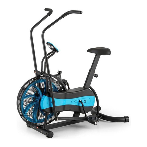
TKO Air Bike User manual

!
PLEASE READ THIS INSTRUCTION MANUAL
BEFORE YOU BEGIN ASSEMBLY
Air Bike Instruction Manual

2
contents
safety informaon 03
customer support 04
assembly instrucons 05
bike features explained 12
user instrucons 13
-
quick start
-
buon func
-
console display and feedback
-
using workout programs
how to take care of
your cycle 16
troubleshoong 16
exercising with your cycle 17
exploded diagrams and parts list 18

3
Safety Information
PLEASE READ THIS INSTRUCTION MANUAL BEFORE YOU BEGIN ASSEMBLY. GREAT
CARE HAS BEEN TAKEN TO DESIGN THESE INSTRUCTIONS AND FOLLOWING THEM
WILL HELPYOUWITH QUICKER ASSEMBLY AND MINIMISETHE RISK OF INJURY
YOU ARE RESPONSIBLE FOR YOUR OWN SAFETY - THIS LIST IS NOT EXHAUSTIVE.
•
Always assemble and operate the product on a level surface
•
Always use the product on a level surface, ensure that the product is stablebeforeuse.
•
Always ensure that the equipment has adequate space on each side and front (the back can be near to a wall).
•
Ensure that the seat height is adjusted correctly - you should be stable and balanced whilst on the saddle.
•
Adjust the seat height to ensure that you have a good downward pedal stroke without overstretching, don’t compromise your
balance.
•
Trytoensurethatyourbackisstraightwhilst exercising, especially for long periods
•
The safety level of this equipment can only be maintained if it is regularly examined for wear and tear
•
Replacedefectivecomponents immediately,and/or keep the equipment out of use until it is repaired.
•
Use only the adjustment settings as described in the instructions. Alwaysusethe correctadjustmentpin/fixing.
•
Always check that any pins / fixings are tight and secure before use and / or after adjustment.
•
Never leave any adjustment devices projecting from the product.
•
Always consult your doctor before undertaking anyexercise program.
•
Always wear suitable clothing andfootwear
e.g. tracksuit / shorts / training shoes
•
Remove all personal jewellery beforeexercising.
!
It is important that you keep these instructions for future reference.

4
Care & Maintenance
•
Always place the equipment in a dry environment.
•
Use a warm, damp cloth to keep the product clean.
•
No wet cleaning of electrical components, unplug before any care andmaintenance
•
The safety level of the equipment can be maintained only if it is regularly examined for damage and wear. This
includes any ropes, pulleys, nuts, bolts, moving parts, bushes, chains, wheels, bearings & connec�on points etc
•
Ensure that you inspect the product regularly - at least once a week is recommended.
•
Ensure that all fixings are �ght before use.
•
Always replace damaged / worn components with original parts from the manufacturer.
Protect the environment by not disposing of this product with household waste.
Check your local authority for recycling advice and facili�es (Europe only).
Customer Support
Should you require any assistance regarding this product please gather the following informa�on,
and then contact us using the details below:
1.
Serial no. - this can be found on
the s�cker below, located as indicated.
Forfuturereference,pleasewritedown
your serial number in the space
provided below.
2.
Original purchase date
3.
Place of purchase
4.
Informa�on about the place
and condi�ons of use
5.
Precise descrip�on of the issue/defect

Assembly Instruc�on
Before you start
1.
Prepare your work area -
it is important you assemble
the product in a clean and
uncluered space.
2.
Work with a friend-
we recommend you have
someone assist you with
the assembly as some of the
components are quite heavy.
3.
Open the carton -
checking any warnings on
the carton and make sure you
have it the right wayup.
4.
Unpack the carton
Make sure you have
the following parts:
Part
No.
1
Main Frame
Fixings Tools and Consumables
M10 x 20mm
Allen Head x 8
Bolt
x 2
M8 Nylon
Locknut x 2
M8 x 30mm
Screw
x 4
M6 x 15mm x 6
Screw
Wrench
Key (8, 6, 5, 4mm)
Phillips
Screwdriver
No.
Part
No.
Part
No.
Part
No.
Part
Allen
No.
Part
No.
Part
No.
Part
Front stabilizer
x 1
Rear stabilizer
x 1
LeHandlebar
x 1
No.
Part
Right Handlebar
x 1
Console Support
Frame x1
Console x 1
Pedalset
x 1pair
No.
Part
Fix Plate
x 2
End Cap
x 2
No.
Part
No.
Part
No.
Part
No.
Part
Foot Peg
x 2
Wrench
No.
Part
No.
Part
No.
Part
No.
Part
01
40
44
83
38 39
74
51 58
48
85
84
108
105
75
Conical sleeve
107
93
Key ( 6, 5, 4mm)
(14/17)
No.
J3
Part
No.
Part
x 8
117

6
Make sure the moving wheels
on the front stabiliser are facing
outward aer assembly.
1.
ach the Front Stabilizer
1-1. Remove the cardboard tube from the front end stabilizer bracket
•
Loosen the two M10 x 20mm Allen Head Bolt (108) from
the cardboard tube and remove the cardboard tube.
•
The cardboard tube is used for packaging pro purposes, which won’t be
used again during the assembly.
108
cardboard tube
1-2. Aach the Front Stabilizer
•
Aach the Front Stabilizer (40) to the Main Frame ( 01) with
four M10 x 20mm Allen Head Bolt(108) and Φ10.5XΦ25*1.5
Arc washer (117),then hten these bolts and washers with
the 6mm Allen Key.
!
!
!
TOOLS:
TOOLS:
Make sure the bolts are fully
htened with the allen key.
Be sure to t the parts in the
same order as the diagrams
shown.
x 4
FIXINGS:
PART
N
O
108
PART
N
O
117
X4
x 2
FIXINGS:
PART
NO
108

44
01
108
117
7
2.
ach the Rear Stabilizer
2-1. Remove the cardboard tube from the rear end stabilizer bracket
•
Loosen the two M10 x 20mm Allen Head Bolt (108) from the cardboard tube
and remove the cardboard tube.
•
The cardboard tube is used for packaging pro purposes, which won’t be
used again during the assembly.
108
cardboard tube
2-2. Aach the Rear Stabilizer
•
Aach the Rear Stabilizer (44)to the Main Frame (01) with
four M10 x 20mm Allen Head Bolt(108)andΦ10.5XΦ25X1.5
Arc washer (117),then hten these bolts and washers with
the 6mm Allen Key..
!
!
TOOLS:
Make sure the bolts are fully
�ghtened with the allen key.
Be sure to fit the parts in the
same order as the diagrams
shown.
x 2
FIXINGS:
PART
NO
108
x 4
FIXINGS:
PART
NO
108
PART
NO
117
X4
TOOLS:

8
Make sure the screws are fully
htened with the allen key.
Be sure to t the parts in the
same order as the dims
shown.
3.
ach the Dual Acon Handlebars
3-1. Aach the LeDual Ac Handlebar
Slide the
leDual Acon Handlebar
onto the pivot axle carefully.
Install the Foot )by screwing it on,and
Tighten it with the wrench as shown.
the
End Cap )onto the Foot )
!
!
3
-
2. Inst
all the Fix Plate & Linkae Bar
Connect the
leual Acn Handleba
and
Lin Bar
with Fix Plate
,
Disc Spacer
,
M8x30mm Scre
and
M8 Nylon Locknut
and ten with 5mm Allen Key &
13/17 Wrench.
Doubly
secure the
Fix P
late
to the Linkage Bar with
three
M6xmm
and secure with 4mm Allen Key.
!
!
Make sure the foot peis fully
htened with the allen key.
Be sure to t the parts in the
same order as the dims
shown.
TOOLS:
Wrench
Wrench
TOOLS:
x 3
x
x
x
FIXINGS:
No.
Part
No.
Part
No.
Part
No.
Part
83
84
83
83
51
01
51
74 75
105
107
93
105
75
93
107
14/17 Wrench.
Wrench
5mm
TOOLS:
4MM
(14/17)

9
3-3. Aach the Right Dual Acon Handlebar
Slide the
right Dual Ac�on Handlebar (58)
onto
the pivot axle carefully.
Install the Foot Peg (83) by screwing it on, and
Tighten it with the wrench as shown.
the
End Cap (84) onto the Foot Peg (83) .
!
!
3-4. Install the Fix Plate & Linkage Bar
Connect the right Dual Ac�on Handlebar (58) and Linkage Bar
with Fix Plate (74) , Disc Spacer(75) , M8x30mm Screw(105) and
M8 Nylon Locknut (93) and hten with 5mm Allen Key &
Wrench.
Doubly secure the Fix Plate (74) to the Linkage Bar with three
M6x15mm Screws (107)and secure with 4mm Allen Key.
!
!
Make sure the screws are fully
�ghtened with the allen key.
Be sure to fit the parts in the
same order as the diagrams
shown.
Make sure the foot peg is fully
�ghtened with the allen key.
Be sure to fit the parts in the
same order as the diagrams
shown.
TOOLS:
Wrench
x 3
x 1
x 1
x 1
FIXINGS:
No.
Part
No.
Part
No.
Part
No.
Part
01
58
84
83
14/17
58
74
105
107
75
93
105
75
93
107
Wrench
5mm
TOOLS:
4MM
(14/17)

10
4.
Attach the Pedals
4-1. Attach the Left Pedal
•
Loosen the Phillip Head Screw (109) fitted
on the left Crank Arm.
•
Attach the Left Pedal (38) to the left Crank Arm
and fasten with the Wrench.
•
Fasten the Phillip Head Screw (109) to the
crank Arm with the 5mm AllenKey.
!
!
!
4-2. Attach the Right Pedal
•
Loosen the Phillip Head Screw (109) fitted
on the right Crank Arm.
•
Attach the Right Pedal (39) to the right
Crank Arm and fasten with the Wrench #14 /
#15.
•
Fasten the Phillip Head Screw (109) to
the Crank Arm with the 5mm AllenKey.
!
!
!
Be sure to fit the parts in the
same order as the diagrams
shown.
This pedal will be threaded on
clockwise.
Make sure the screw is fully
tightened with the allen key.
This pedal will be threaded on
clockwise.
Be sure to fit the parts in the
same order as the diagrams
shown.
Make sure the screw is fully
tightened with the allen key.
39
109
38
109
Wrench
TOOLS:

11
Make sure the screws are fully
�ghtened with the allen key.
!
!
5.
ach the Console Support
Connect the Sensor Cable and Middle Wire together
and then aach the Console Support (48)to the front end
of the Main Frame (01) with two M8x30 mm Screws (105)
and secure with the 5mm Allen Key.
!
!
middle wire
sensor wire
!
wire
connect
6.
ach the Console
Remove the four ng screws which are located in the back of
the Console(85) .
Connect the Console Cable and Middle Wire together and
then aach the Console (85) to the Console Support (48)
with four M5 x 12mm fixingscrews(106) and
secure with the Screwdriver.
Be sure to fit the parts in the
same order as the diagrams
shown.
Make sure the cables are fully
connected.
!
console
cable
middle
wire
Final Checks
Your cycle is now assembled. Please make the following nal checks before you use it for the t
Make sure all screws, bolts and nuts are ghtened securely
Make sure you have posid it on a at, level surface
5mm
TOOLS:
Phillips
Screwdriver
TOOLS:
Make sure the screws are fully
�ghtened with the screwdriver.
Make sure the cables are fully
connected.
Be sure to fit the parts in the
same order as the diagrams
shown.
FIXINGS:
Part
No.
2
4
FIXINGS:
No.
Part
01
48
105
106
48
85
106
105

12
Bike Features Explained
Adjusting the seat reach
1.
Pull up the Adjustment Grip (62) and adjust
the reach of the Saddle.
2.
Release the Adjustment Grip (62) after the
proper saddle position had found.
!
Adjusting the seat height
1.
Pull up the Cam Handle (76) and adjust the
height of the Saddle Post.
2.
Press down the Cam Handle (76) afterthe
proper saddle position had found.
!
Levelling your air bike
1. To help you level the cycle on uneven surface, 2 height
adjustersareincludedonthe rear stabilisers.Simply turn it
to adjust the height of the airbike.
Transporting your air bike
1.
Your air bike has 2 transport wheels on the front
stabilizer.
2.
Lift the bike from the rear end of bike and then
pull or push to move itaround.
Do not pull the seat post out too far –the
maximum is indicated on the seat post.
Do not pull the seat post out too far –the
maximum is indicated on the seat post.
A51
5

Computer instruction
13
STARTENTERSTOP
interval
target
time
target
distance
target
calories
target
HR
WARNING:
Heart rate monitoring systems
may be inaccurate.If you feel
pain, faintness,or dizziness,
stop exercising immediately.

Operating the console:
1. QUICK START OPERATION
Under STAND BY display, the user can enter “QUICK START” mode by pressing the “START” button. And then
“TIME, DISTANCE, CALORIES” will ready to count up from zero. After starting the machine, the lever of resistance
can be adjusted manually. The system will pause counting TIME/DISTANCE/CALORIES if not receiving RPM
signals. The system will continue previous counting once receiving RPM signal. While using, pressing “STOP”
button will cease the operation of the console.
2. INTERVAL – PROGRAM
Under STANDBY DISPLAY, pressing “INTERVAL” button one time can enter default setting of interval 20/10
program ; pressing two times continuously can do the setting in Interval 10/20 program ; pressing three times
continuously can enter Interval Custom Program to set your own settings.
(A). Setting interval laps on Interval 20/10 Program
Under operating status, when choosing Interval 20/10, Internal 0/10 display will blink, the user can do the setting
using “UP/DOWN” button. Press “ENTER” when setting is finished and then press “START” to run the program.
When pressing “START”, the program will operate based on WORK TIME 20 seconds/ REST TIME 10 seconds.
Interval takes record on each cycle until reaching the setting laps.
(B). Setting Interval laps on INTERVAL 10/20 program
Under STANDBY mode, when choosing INTERVAL 10/20 program, “ INTERVAL 0/10” display will blink. Use
“UP/DOWN” button to do the setting. Press “ENTER” when finishing the setting and then press “START” to start the
workout.
When pressing “START”, the program will operate based on WORK TIME 10 seconds/ REST TIME 20 seconds.
Interval takes record on each cycle until reaching the setting laps.
(C). Operation on INTERVAL CUSTOM mode
Under STANDBY DISPLAY, when choosing “INTERVAL CUSTOM”, “WORK TIME” will blink.
(1). Setting “WORK TIME”
Use “UP/DOWN” button to set the time on “WORK TIME”. Press “ENTER” when finish the setting, and the program
will switch to display on the next setting column.
(2). Setting “REST TIME”
Use “UP/DOWN” button to set the REST TIME. Press “ENTER” when finish the setting, and the program will switch
to display on the next setting column.
(3). Setting on INTERVAL laps
Use “UP/DOWN” button to set the INTEVAL laps. Press “ENTER” when the setting is finished. Press “START” to
begin the workout.
When pressing “START”, the program will operate based on WORK TIME/ TEST TIME the user has set. Interval
takes record on each cycle until reaching the setting laps.
14

3. TARGET TIME – PROGRAM
Under STANDBY DISPLAY, pressing “TIME” program will enter the operation of this program.
(1). Setting TIME
When choosing TIME PROGRAM and pressing “ENTER”, the program switch to the default time of 30 seconds in
blinking display.
Press “UP/DOWN” button to set TIME or not changing the default time, press “ENTER” to save the setting.
(2). The processing mode after “START”
a. Under processing mode, TIME counts in decrement, DISTANCE/CALORIES counts in increment.
b. Console will stop function when pressing “STOP” during operation.
4. TARGET DISTANCE – PROGRAM
Under STANDBY DISPLAY, press “DISTANCE” program to enter the setting of this program.
(1). Setting DISTANCE
When choosing DISTANCE PROGRAM and pressing “ENTER”, the program switches to the default setting of 5.00
and display in blink.
Press “UP/DOWN” button to set DISTANCE or not changing the default distance. Press “ENTER” to save the setting.
(2). The processing mode after “START”
a. Under processing mode, DISTANCE display counts in decrement, TIME/CALORIES counts in increment.
b. Console will stop function when pressing “STOP” during operation.
5. TARGET CALORIES – PROGRAM
Under STANDBY DISPLAY, pressing “CALORIES” program to enter the setting of this program.
(1). Setting CALORIES
When choosing CALORIES PROGRAM and pressing “ENTER”, the program switches to the default setting of 50
calories and display in blink.
Press “UP/DOWN” button to set CALORIES or not changing the default calories. Press “ENTER” to save the setting.
(2). The processing mode after “START”
a. Under processing mode, CALORIES display counts in decrement, TIME/DISTANCE counts in increment.
b. Console will stop function when pressing “STOP” during operation.
6. TARGET HR PROGRAM
Under STANDBY DISPLAY, press “HR” program to enter the setting of this program.
(1). Setting AGE
When pressing HR program, console displays initial age setting of 30 years old. Press “UP/DOWN” button to setting
age, and press “ENTER” to save the setting. Press “START” to begin the workout.
(2). The processing mode after “START”
a. Under processing mode, TIME/DISTANCE/CALORIES display counts in increment.
b. Console will stop function when pressing “STOP” during operation.
15

16
How to Take Care of Your Cycle
Storage
Keep the equipment in a dry place with as
little temperature variation as possible.
Try to protect from dust and always
unplug when not in use (ifapplicable).
Cleaning
Use a warm, damp cloth to wipe the
surfaces. Mild detergent may be used if
necessary.
!
Maintenance
Ensure you regularly check components
for wear and make sure all the nuts and
bolts are tightened before each exercise
session.
Troubleshooting
!
If you are having problems with your heart rate reading please note that some fibres used in clothes eg)
polyester, create static electricity that may prevent a reliable heart rate reading. Mobile phones, TV’s,
microwaves and other electrical appliances that generate an electromagnetic field may also interfere with
heart rate measurement.
If you are still having problems with your equipment, please get in touch with your local distributor using
the details found in the Customer Support section on page 5.
Ifyou have a problem with your equipment, before youdoanythingelse please check thatall
thecables havebeenconnectedcorrectly. Loose cablesare verycommonandmany problems
can be solved by making sure the cables are properly connected
Never remove the protective casing.

17
!
Exercising with Your Cycle
!
Starting and finishing your workout
Begin and end each workout with a Warm Up / Down session –a few minutes of stretching to help prevent strains,
pulls and cramps
Correct cycling form
•
Sit on the cycle, with your feet on the pedals and inside the
pedal straps
•
Ensure that the seat height is adjusted correctly - you should
be stable and balanced whilst on the saddle. The basic rule
How long should I exercisefor?
That really depends on your current level offitness. Ifyou’re
just starting out on a new exercise program, you should
start gradually and build up –do not try to do too much too
quickly. 30 minutes,
for getting the seat height right is that as the pedal reaches its 3 times a week should be enough.
lowest point, the leg is almost straight.
•
Tryto ensurethatyourbackisstraightwhilst exercising,
especially for long periods.
Don’t push yourself too hard - you should never feel
exhausted during or following exercise.
Heart Rate Training
To get the most out of your new piece of fitness equipment
and see the best results from your training you should exercise
at the right level of effort, and that means listening to your
heart! Working out to a target heart rate means you can
direct your workout to achieve differentgoals:
Good health - For those wishing to improve quality of life
and general well being. Your sessions will need to be
done at an intensity of between 50-60% of your estimated
maximum heart rate, should last about 30 minutes and can
be done on most days of the week.
Weight loss –To see a significant reduction in body fat, your
sessions must be a little more intense - between 60 and
70%ofyour estimated maximum heart rate. These sessions
can also be performed on most days of the week for up to
30 minutes.
Improving Fitness levels –These sessions should be
performed at 70-80% of your estimated maximum heart
rate and can also involve bouts of interval training that
would have your heart rate peaking for short times near
yourmaximumheartratelevel.Theseareintensesessions
and will require at least a 48 hour rest between sessions.
Calculating your target heart rate
First, you need to find your estimated maximum heart rate
using theformula‘220 minus your age in years’.So, ifyou are
35 years old your estimated maximum heart rate is:
220 –35 = 185 beats per minute (bpm)
Next,tocalculateyourtarget heartrate,simply multiplyyour
estimated maximum heart rate (185bpm) by the applicable
percentage. So, if your goal is better heath:
185 x 60% = 111bpm
Note: Heart rate training requires you to monitor your heart
rate throughout the workout. For this we recommend using a
chest strap (if your machine has a wireless receiver) or a heart
rate monitor.
NOTE: The important issue to remember with all
estimated calculations is that they are just estimates –
if you don’t feel comfortable exercising at your target
then reduce it to a level you are comfortable with.
If you experience nausea, dizziness or other abnormal
symptoms during exercise, stop at once and consult
your doctor
Always consult your doctor
before undertaking a new
exercise regime

18
Expolded Diagram

Parts List
NO Name of the product Q'TY NO Name of the product Q'TY
01 Main Frame 1 45 Adjustment board 1
02 Fan wheel hub set 1 46 Foot pad 2
03 Fan wheel 1 47 Rear foot pipe plug 1
04 Fan wheel hub sleeve 1 48 Console support 1
05 Fan wheel hub sleeve 1 49 Circular tube plug 2
06 Fan hub 1 50 Wire plug 2
07 Bearing 6301Z 1 51 Left dual action handlebar 1
08 Bearing 6901Z 3 52 Dipping plastic 1
09 Left protection network group 1 53 Bearing 6003Z 2
10 Right protection network group 1 54 Bearing 6202Z 2
11 Protection network hoops 1 55 Bearing 6203Z 2
12 Protective net compression sheet 2 56 C-type buckle 2
13 Baffle 2 57 Pipe inside plug 2
14 Cat eye screw M8*45 2 58 Right dual action handlebar 1
15 Cap M8 2 59 Dipping plastic 1
16 Crankshaft center 1 60 Seat cushion up and down adjustment group 1
17 Pulley 1 61 Seat cushion front and rear adjustment group 1
18 Right-square crank 1 62 Socket wrench welding part 1
19 C-type buckle 1 63 Adjustable wrench with plastic sheath 1
20 Elastic cylindrical pin 1 64 Seat cushion adjustable short shaft 1
21 Bearing 6005 2 65 Seat cushion adjustable long pressure spring 1
22 Crankshaft center lock nut 1 66 Set piece 1
23 Left - square crank 1 67 Seat cushion adjustable short pressure spring 1
24 Left – disc crank group 1 68 Seat cushion adjustable small sleeve 1
25 Bearing 22052RS/NR 2 69 Seat cushion adjustable long shaft 1
26 Left - swing arm link 1 70 Seat adjustable positioning steel ball 1
27 C-type buckle 4 71 Pipe plug 1
28 Right-disc crank group 1 72 Seat cushion holder 1
29 Right-swing arm ling 1 73 Seat cushion 1
30 Left protection cover 1 74 Front outboard piece 1
31 Right protection cover 1 75 Conical sleeve 2
32 Crank guard-down 1 76 Wrench handle 1
33 Crank guard-on 1 77 Powder metallurgy 2
34 Left-front decorative cover 1 79 Adjustable pressure quick thin liner 1
35 Right-front decorative cover 1 80 Press bushing 1
36 Seat tube outside the hollow set 1 81 Compression block 1
37 Belt 1 82 Reset spring 1
38 Left pedal 1 83 Aluminium alloy pedal 2
39 Right pedal 1 84 Decorative plug 2
40 Forefoot tube group 1 85 Console 1
41 Round plug 2 86 Induced magnet 1
42 Square foot pad 2 87 Cylindrical head socket screw M8*20 1
43 Moving wheels 2 88 Cylindrical head socket screw M5*12 8
44 Rear foot tube group 1 89 Hex nut M12*1.25 4
19

No. Name of the product QTY No. Name of the product QTY
90 Cylindrical head socket screw M6*12 6 107 Countersunk head socket screw M6*15 6
91 Cylindrical head socket screw M10*40 4 108 Umbrella head socket screw M10*20 8
92 Cylindrical head socket screw M6*20 1 109 Cylindrical head socket screw M6*10 2
93 Cap M8 5 110 Umbrella head socket screw M8*50 1
94 Flat washer 3 111 Spring washer M8 1
95 Cylindrical head socket screw M6*16 1 112 Cylindrical head socket screw M5*6 3
96 Pan head cross self tapping screw ST4*10 7 113 Allen key 4MM/5MM/6MM 1+1+1
97 Countersunk head cross screw M6*15 2 114 Wrench(14/17) 1
98 Cap M6 1 115 Wrench 1
99 Cylindrical head socket screw M6*35 1 116 Phillips screwdriver 1
100 Pan head cross self tapping screw ST4*15 12 117 Arc washer 8
101 Countersunk head cross screw M4*10 4 119 Press spring 2
102 Umbrella head socket screw M8*50 2 120 Right hollow plug 1
103 Cap screw M8 3 121Left hollow plug 1
104 Pan head cross screw M5*8 4
105 Countersunk head socket screw M8*30 4
106 Pan head cross screw M5*12 4
20
Table of contents
Other TKO Exercise Bike manuals
