TKR Group 83 30 2 299 380 User manual

Automotive measuring lead set
Operating manual
83 30 2 299 380

Section Page
Safety
1.1 Explanation of symbols 2
1.2 Information regarding this manual 3
1.3 Operating principles 3
1.4 Safety instructions 3
Scope of supply
2.1 Scope of Supply – Accessories 5
2.2 Scope of Supply – Measuring Leads 6
Use
3.1 Open case 8
3.2 Positioning the lead marker 8
3.3 Determining the right measuring lead 9
3.4 Connecting with a Y-lead 10
3.5 Connecting with an I-lead 11
3.6 Bridging the safety fuse 12
3.7 Testing 13
3.8 Measurement instrument connectivity 14
Service
4.1 Spare parts 15
1.
2.
3.
4.
Observe the instruction
manual
Pacemaker-wearers
prohibited
Warning:
General source of danger
1.1 Explanation of symbols
In this instruction manual, some sections use internationally known warning symbols, warning notes and general
instructional symbols.
The individual symbols are explained below. Follow all instructions and safety rules.
Warning: dangerous
electric voltage
Please note
the following
Arrow to clarify compres-
sion
Arrow showing direction
For more information, see
section …
Audibly engage
This instruction manual is protected by copyright. Any use beyond the restrictions imposed by copyright legislation undertaken without the permission of the
publisher is forbidden and punishable. This also applies to the extraction of individual illustrations and the use of texts in extract form.

3
State-of-the-art
Technical
modifications
Read instruction manual
Handling
1.2 Information regarding this manual
1.4 Safety instructions
This automotive measuring lead set represents state-of-the-art technology. To ensure functionality,
it must be operated in a proper and safe manner.
In the interests of quality assurance, we reserve the unrestricted right to proceed with
technical modifications arising out of further developments in technology and product
improvements, without prior notification.
Read the instruction manual carefully before using the automotive measuring lead set.
All handling necessary to ensure correct operation is described in the instruction manual. No
methods of working other than those approved by the manufacturer may be undertaken.
Read the operating instructions.
Observe caution when touching hot components: risk of burns.
Do not use the measuring lead set if any leads are faulty.
Do not allow leads to hang over the edge of the desk, working area or counter, or come into
contact with hot manifolds or moving parts.
Always replace leads so they lie loosely in the carry-case. Make sure that they do not get jam-
med!
To reduce the risk of electrical shock, do not use the measuring lead set on wet surfaces or in
the rain.
Only use the measuring lead set in the manner described in these operating instructions.
Only use accessories approved by BMW.
1.3 Operating principles
Our automotive measuring lead set has been developed specially for making contact with
almost all plug connectors found in the automotive sector. With its numerous possible
combinations it is suitable for universal use. Many innovative details permit flexible and reliable
fault diagnosis.

4
1.4 Safety instructions
Usage as described in
instruction manual
Improper use
Warranty
Important Notes for
Maintenance
Service address
The automotive measuring lead set is intended exclusively for testing voltages and currents in
the automotive sector. The tool must only be used for purposes which do not entail any risk
to man and machine.
The automotive measuring lead set must be used only as described in the operating instructions.
Any modification of the automotive measuring lead set or other usage forms are the responsibility
of the user.
Make sure that the automotive measuring lead set is in perfect condition and that it has all
functionality necessary to ensure safe operation.
Follow all health and safety regulations in the country of operation. Wear personal protection
equipment.
Use of the tool by personnel that have not been trained and instructed is prohibited.
Make sure that the automotive measuring lead set is used in a work area that is free from heat
sources (max. 50C / 122F), corrosive liquids, oil and grease.
The automotive measuring lead set must never be used in any areas where there is a risk of
explosion.
Only use tools and accessories that do not show signs or wear or damage. Damaged tools or
accessories can lead to serious injury.
The manufacturer accepts no liability for damage or injury caused by improper repair or use
of non-original spare parts.
Any incorrect use of the automotive measuring lead set resulting in damage to either the
appliance or the vehicle nullifies the warranty.
In the event of any noticeable damage, the components must be replaced. Damaged compo-
nents can lead to serious injury.
Use only original spare parts. Check contacts and connections for damage.
For further details please contact our service address:
TKR Automotive GmbH
Am Waldesrand 9-11
D-58285 Gevelsberg (Germany)

5
Automotive measuring lead set
Operating manual
Automotive Messkabel-Set
Bedienungsanleitung
2.1 Scope of Supply – Accessories
83 30 2 299 394
Contact gauge,
1 pc.
83 30 2 299 399
Extension lead, 2 m,
1 set
83 30 2 299 404
Blade-type safety fuse adap-
ters, 1 set
83 30 2 299 408
Terminal clips, red and black,
1 pair
83 30 2 299 407
Test prods, red and black,
1 pair
83 30 2 299 400
Connector plugs,
1 set
83 30 2 333 697
Lead markers,
1 set
Instruction manual
83 30 2 299 380
2 .1.1
2.1.5
2.1.2
2.1.6
2.1.3
2.1.7
2.1.4
2.1.8

6
2.2 Scope of Supply – Measuring Leads
Item BMW No.
1) Contact dimension WxD
2) Lead Ø
3) Permitted up to max. A
Case contents Illustration
183 30 2 328 993
1) 0.63x0.63 mm
2) 0.75 mm2
3) 3A
2 pairs
283 30 2 329 115
1) 1.20x0.60 mm
2) 0.75 mm2
3) 6A
2 pairs
383 30 2 329 116
1) 1.50x0.60 mm
2) 1.00 mm2
3) 10A
2 pairs
483 30 2 329 156
1) 2.80x0.80 mm
2) 1.50 mm2
3) 13A
2 pairs
83 30 2 299 380

7
Item BMW No.
1) Contact dimension WxD
2) Lead Ø
3) Permitted up to max. A
Case contents Illustration
583 30 2 333 580
1) 4.80x0.80 mm
2) 2.50 mm2
3) 16A
2 pairs
683 30 2 333 584
1) 5.20x0.63 mm
2) 2.50 mm2
3) 16A
2 pairs
783 30 2 333 615
1) 6.30x0.80 mm
2) 2.50 mm2
3) 16A
1 pair
883 30 2 333 619
1) 9.50x1.20 mm
2) 4.00 mm2
3) 25A
1 pair
983 30 2 333 623
1) Ø 0.80 mm
2) 0.75 mm2
3) 3A
2 pairs
10 83 30 2 333 625
1) Ø 1.50 mm
2) 2.50 mm2
3) 6A
1 pair
11 83 30 2 333 694
1) Ø 2.50 mm
2) 2.50 mm2
3) 16A
2 pairs
12 83 30 2 333 695
1) Ø 3.50 mm
2) 1.50 mm2
3) 10A
1 pair
13 83 30 2 333 696
1) Ø 4.00 mm
2) 2.50 mm2
3) 16A
1 pair

8
3.1 Open case
3.2 Positioning the lead marker
3 .1.1 3.1.2
3.1.3
3.2.1 3.2.2

9
7 7
3
3.3.2
Judge the initial selection of the right gauge for the casing
by eye.
3.3.3 – 3.3.6
Check the choice of gauge is correct.
3.3.7
The matching test lead set in each case is identified with the
same number as that printed on the gauge selected.
The letter on the lead is for differentiation purposes, where a
number of test leads with the same number are being used
at the same time.
3.3 Determining the right measuring lead
3.3.3 3.3.4
3.3.5
3.3.23.3.1
3.3.6
3.3.7

10
3 A
3 A
3 B
3 B
3.4.4
When using a number of measuring leads,
always ensure that the leads marked A and B
are correctly assigned.
3.4.5
Always connect the measuring instrument
first – the bare ends of the leads must never
come into accidental contact with the
bodywork or other bare metal parts.
3.4.1
Socket-side connection
3.4.2
Plug-side connection
3.4.3, 3.4.4
T-pieces allow test leads to be connected to measuring
leads. A Y-lead of this kind guarantees max. conductivity in
the consumer path. The voltage measured is tapped off.
3.4 Connecting with a Y-lead
Connection
see Fig. 3.4.1
Connection
see Fig. 3.4.2
1 2
1
2
3.4.1
3.4.3
3.4.5
3.4.4
3.4.2
3.4.6

11
3B
3.5 Connecting with an I-lead
3.5.1
Socket-side connection
3.5.2
Connecting to ground potential
3.5.3 – 3.5.5
I-connection – test leads to measuring leads
3.5.6
Always connect the measuring instrument
first – the bare ends of the leads must never
come into accidental contact with the
bodywork or other bare metal parts. 1 2
Connection
see Fig. 3.5.2
Connection
see Fig. 3.5.1
1
2
3.5.1
3.5.3 3.5.4
3.5.5
3.5.2
3.5.6

12
7
3
7
3.6 Bridging the safety fuse
Warning:
Any measurements before the safety fuse must be carried out by professionally qualified personnel only.
Warning:
You are working in an unprotected current circuit. Bridging safety fuses can result in subsequent
damage to the vehicle‘s electrical and electronics systems.
3.7.4
Always ensure that you connect up the measuring instrument first, so that no bare lead ends can come
into contact with the bodywork.
Bare lead ends could produce a short circuit and even cause the lead to catch fire.
3.7.1 3.7.2
3.7.3 3.7.4
3.7.5 3.7.6

13
3.7 Testing
3.6.1 3.6.2
3.6.3 3.6.4
3.6.5 3.6.6
14
3 A
3 A
3B
3 A
3 A
3 B
3 B
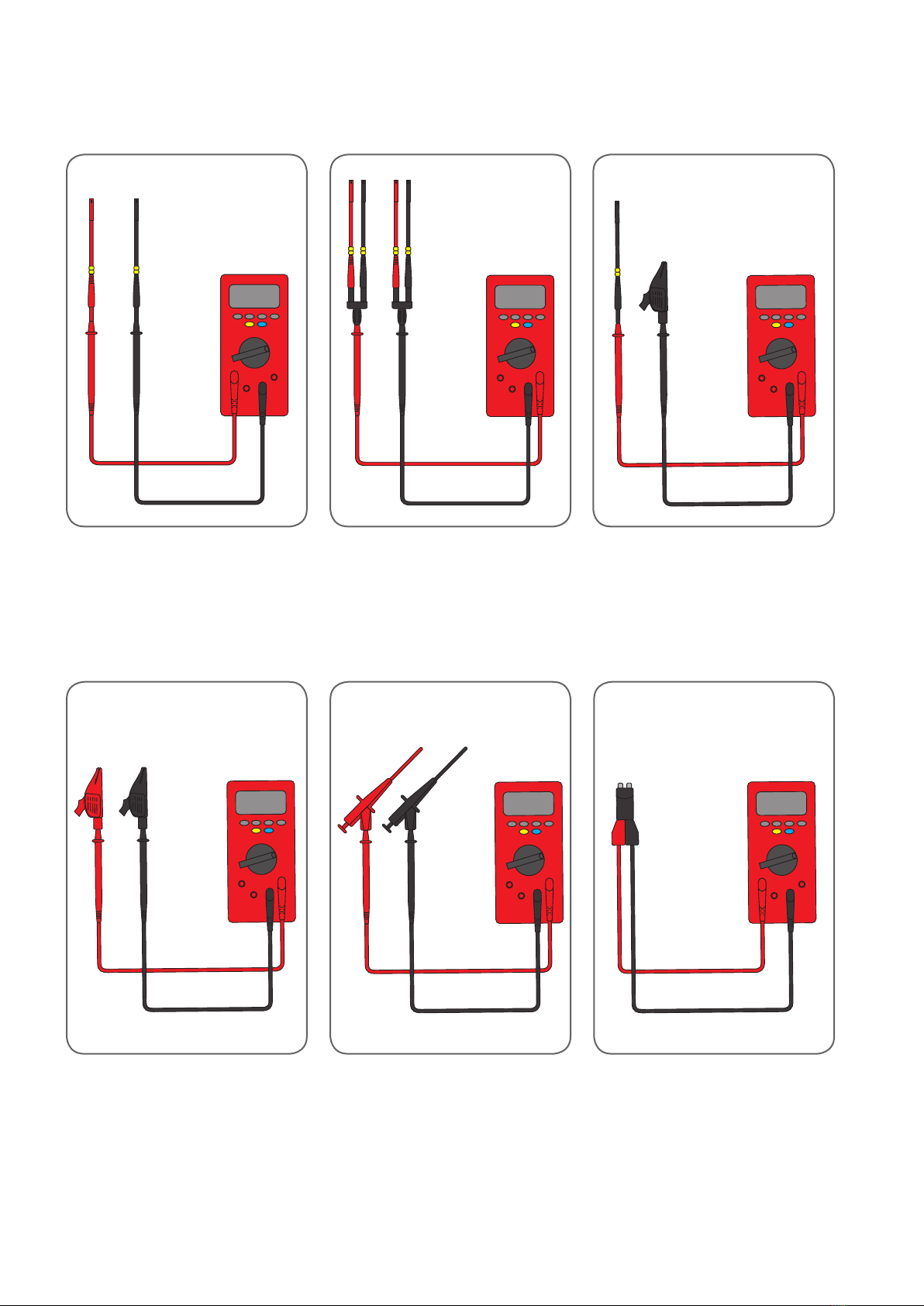
3.8 Measurement instrument connectivity
3.8.1
I-connector for current measurement
3.8.2
Y-connector for voltage measurement
3.8.3
Plug combination with respect to
ground - predominantly for measuring
voltage, current measurement also
possible
3.8.4 – 3.8.6
Measurement instrument equipped with universal alligator clips for widest variety of uses.
3.8.1 3.8.33.8.2
3.8.4 3.8.63.8.5

15
4.1 Spare parts
The individual items described in this guide are integral parts of the case and can
be re-ordered as spare parts or additions to the set.
Test lead sets can be re-ordered as spare parts or as additions. This means that
entire plug connectors with a number of identical contacts can be tested. Depen-
ding on the number of poles, as many test leads as required can be added. The
case has spaces available for the purpose.
BMW No. Designation Unit
83 30 2 299 394 Contact gauge 1 pc.
83 30 2 299 399 Extension lead, 2 m 1 set
83 30 2 299 408 Terminal clips, red and black 1 pair
83 30 2 299 407 Test prods, red and black 1 pair
83 30 2 299 400 Connector plugs 1 set
83 30 2 333 697 Lead markers 1 set
83 30 2 299 404 Blade-type safety fuse adapters 1 set
83 30 2 328 993 Measuring leads, 0.63x0.63 mm 1 pair
83 30 2 329 115 Measuring leads, 1.20x0.60 mm 1 pair
83 30 2 329 116 Measuring leads, 1.50x0.60 mm 1 pair
83 30 2 329 156 Measuring leads, 2.80x0.80 mm 1 pair
83 30 2 333 580 Measuring leads, 4.80x0.80 mm 1 pair
83 30 2 333 584 Measuring leads, 5.20x0.63 mm 1 pair
83 30 2 333 615 Measuring leads, 6.30x0.80 mm 1 pair
83 30 2 333 619 Measuring leads, 9.50x1.20 mm 1 pair
83 30 2 333 623 Measuring leads Ø 0.80 mm 1 pair
83 30 2 333 625 Measuring leads Ø 1.50 mm 1 pair
83 30 2 333 694 Measuring leads Ø 2.50 mm 1 pair
83 30 2 333 695 Measuring leads Ø 3.50 mm 1 pair
83 30 2 333 696 Measuring leads Ø 4.00 mm 1 pair

Am Waldesrand 9-11
D-58285 Gevelsberg (Germany)
Phone +49 2332 66607-77
Fax +49 2332 66607-51
E-mail info@tkrgroup.com
Internet www.tkrgroup.com
Zubehör und Ersatzteile:
www.tkr-powertools.com
DOK-BMW-00000001, Vers. 12.11
Table of contents


