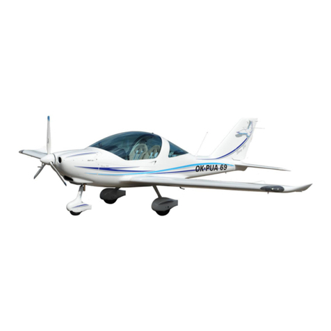
TL Ultralight TL-96 STAR Quick start guide

Flight and Operational Manual
TL- 96 STAR s/n 99 S 25
Notice! The information contained in this document is for reference and information only.
The pilot is the final and only responsible party for the safe operation of this aircraft.
- 1 -
T L - U L T R A L I G H T
Letiště 515, Pouchov
503 41 Hradec Králové
tel/fax 049 5213378
tel +42049 5218910
tel +42049 5211753
info@tl-ultralight.cz
www.tl-ultralight.cz
T L - 96 STAR
F l i g h t a n d o p e r a t i o n a l m a n u a l
Published in December 2000
Serial number: 99 S 25 Registration nmr.:
Revision: 1/8.10.2018

Flight and Operational Manual
TL- 96 STAR s/n 99 S 25
Notice! The information contained in this document is for reference and information only.
The pilot is the final and only responsible party for the safe operation of this aircraft.
- 2 -
1. General information 6
1.1. Important information 6
1.2. Description of airplane 6
1.2.1. Airframe 6
1.2.2. Fuelsystem 7
1.2.3. Propeller 7
1.2.4. Engine 7
1.2.5. Meaning of movement of control component units 8
1.2.6. Basic technical data of the airplane 8
1.3. Layout of the airplane 9
1.4. Detecting the center of gravity position, allowed and measured values 10
1.4.1. Weighting the airplane for the the headmost center of gravity 10
1.4.2. Weighting the airplane for the backmost center of gravity 10
1.4.3. Measured values of the center of gravity for the airplane TL-96 Star before
test flying 11
2. Operating restrictions 11
2.1. Restriction of the speed of the flight and reparation of position fault of
airspeed indicator 11
2.1.1. Airspeed ind. data reparation regarding the position fault of Pitot tube 12
2.1.2. Reparation table of real and indicated air-velocity 12
2.2. Weights and loads 12
2.2.1. Maximum and minimum weights 12
2.2.2. Siting of the load 12
2.3. Engine operating restrictions 13
2.4. Propeller operating restrictions 13
2.4. Fuel and lubricant oil 13
2.4.1. Fuel Tank 14
2.4.2. Consumption of the fuel 14
2.5. Restriction of maneuver 15
2.5.1. Allowed turns 15
2.5.2. Flight multiples 15
2.6. The crew 15
2.6.1. Minimal and maximal weight of the crew 15
2.6.2. Pilot qualification 16
2.6.3. Pilot´s place on the plane, ageof the crew, application of seat belts 16
2.7. Maximum flight height 17
2.8. Meterologic condition restriction 17
2.9. Carriage of baggage restriction 17
2.10. Types of airport traffic 17
3. Emergency process 18
3.1. Misfire of the engine 18
3.1.1. Misfire of the engine during the flight to the height 200m 18
3.1.2. Misfire of the engine during the flight above the height 200m 18
3.2. Fire on board of the plane 18
3.3. Vibrations 18

Flight and Operational Manual
TL- 96 STAR s/n 99 S 25
Notice! The information contained in this document is for reference and information only.
The pilot is the final and only responsible party for the safe operation of this aircraft.
- 3 -
3.4. Undercarriage failure 19
3.4.1. Main undercarriage failure 19
3.4.2. Nose undercarriage failure 19
3.5. Using the rescue system 19
4. Normal processes 20
4.1. Starting up the engine 20
4.2. Engine test 20
4.3. Important parts made before getting off 21
4.4. Taxying 21
4.5. Taking-off 22
4.5.1. Maximum power of wind at time of taking off 22
4.6. Tasks after reaching the flight level 22
4.7. Flight at the flight level 22
4.8. Descend 22
4.8.1. Sideslid 23
4.9. Landing 23
4.10. Tasks after landing 23
4.11. Pilotage in lateral wind 23
4.12. Flight in turbulent atmosphere 24
4.13. Standing up to the lane 24
5. Output 24
5.1. Conditions for output assessment 24
5.2. Speeds 24
5.3. Rate of climbs and height loss from the beginning of stalling 24
5.4. Ceiling 25
5.5. Gliding range 25
5.6. Getting off length 25
5.7. Landing length 25
5.8. Flight persistency 25
5.9. Flying range 26
6. Maintenance and operating the plane 27
6.1. Parking 27
6.2. Anchoring the plane 27
6.3. Manipulation with the plane 27
6.4. Assembly and disassembly of the plane 27
6.4.1. Disassembly of the plane 27
6.4.2. Assembly of the plane 28
6.5. Washing and cleaning the plane 28
6.6. Before flight inspection 29
6.7. Filling the fuel 30
7. Service life of the flight and maintenance periodicity 31
7.1. Service life of the plane and its parts 31
7.2. Workaday maintenance 31

Flight and Operational Manual
TL- 96 STAR s/n 99 S 25
Notice! The information contained in this document is for reference and information only.
The pilot is the final and only responsible party for the safe operation of this aircraft.
- 4 -
7.2.1. Lubricant plan and lubricant preparation 32
7.2.2. Blocking, raising and jogging along preparation 32
7.2.3. Disassembly of front wheel 32
7.2.4. Wheel disassembly of main undercarriage 33
7.2.5. Mending the tyre 33
7.2.6. Electrical system voltage 33
7.2.7. Tolerance and setting up values 33
7.2.8. Supporting and subordinate construction 33
7.2.9. Special assembly, controlling and setting preparations 34
7.2.10. Special tools 34
7.2.11. Materials for small reparations 34
7.2.12. Changing the fuel filter in the engine area 34
7.2.13. Maintenance of airscrew SR 2000 xa 35
7.3. Contract revision 35
7.4. Periodical revision after every 50hours 35
7.5. Periodical revision after every 100hours 35
7.6. Periodical revision after every 200hours 35
7.7. Periodical revision after every 300hours 35
7.8. Jacking points on the plane 36
7.9. List of labels and their placing 36
8. Airplane repairs 36
8.1. Repairs of connection screw 36
8.2. Repairs of rivet joints 37
8.3. Pilotage repairs 37
8.4. Airframe repair 37
8.5. Fuel system repairs 37
8.6. Engine repairs 37
8.7. Electroinstalment and appliance repairs 37
8.8. Revision of electroinstalment 38
9. Engine Rotax 912/912S maintenance 38
9.1. Oil refill 38
9.2. Sparking plugs 38
9.3. Refregarating liquid 38
9.4. Service life of the plane, revisions and inspection of the engine 39
9.5. Service life of rubber parts of engine 40
Dear airplane owner,

Flight and Operational Manual
TL- 96 STAR s/n 99 S 25
Notice! The information contained in this document is for reference and information only.
The pilot is the final and only responsible party for the safe operation of this aircraft.
- 5 -
I would like to compliment you on the purchase of the ultralight airplane TL-96
Star which is the result of many years of development of our company. This
company belongs, in its category, to European top.
With its output, TL-96 Star is getting near the small sports airplanes category, but
flying with TL-96 Star is much economical and its maintenance is also much easier.
I believe that the aircraft will operate for your enjoyment for very long time and it
will satisfy you. Also this Flight and operating guidebook should help you. You can
find operating and maintenance information in this guidebook. Inseparable part of
this guidebook is instruction for using the engine, airscrew and respectively the
saving system.
I wish you a lot of joy from flying with Your new aircraft TL- 96 Star.
In Hradec Králové July 27, 1999
Jiří Tlustý
owner of TL-ULTRALIGHT
TL Ultralight s.r.o.
Letiště 515, Pouchov
503 41 Hradec Králové
tel/fax +420049 5213378
tel +420495218910
tel +420495211753
info@tl-ultralight.cz
www.tl-ultralight.cz

Flight and Operational Manual
TL- 96 STAR s/n 99 S 25
Notice! The information contained in this document is for reference and information only.
The pilot is the final and only responsible party for the safe operation of this aircraft.
- 6 -
1.General information
In case that this guidebook reveals to the rule UL1, UL 2 or UL 3, it is only a calling off
corresponding rule of Letecké amatérské asociace české republiky – Czech republic amateur
flight association. This association is encharged by Úřad pro civilní letectví-Office for civil
aviation.
1.1.Important information
Every airplane holder, operational organization and pilot of the airplane TL-93 Star must
acquaint with this guidebook at its full lenght. This phamlet consists of flying and maintenance
part of this type of airplane. This phamlet must be on board of the plane within other
documents at all flights.
Its inseparable parts are the operating instructions for engine, airscrew and respectively
saving system.
This airplane is intended to sports and recreational purposes. Also for perfoming basic and
continuative practice. It is certificated by technical guideline UL 2 and it is not allowed to
make commercial flights with the exception of practice and the lease.
This guidebook is valid only if the changes send to the airplane holder TL-96 Star
are put into effect. These changes are gradually paginated and they contain removable
pages. Respective pages should be changed in the guidebook. If there is no page with such
number, new page is subsumed due to the sort order.
ATTENTION
This airplane belongs to the sports and recreational category and is dateless to the
approbation of Úřad pro civilní letectví v ČR-Office for civil aviation in Czech
Republic. Operating this airplane at one own risk.
1.2.Description of the airplane
1.2.1. Airframe
Ultralight airplane TL-96 Star is two-placed full composite low wing plane with flowing
elevator.
The fuselage is laminated, in some places made into sandwich, with oval cross section shaped
to achieve the propitious proportion among the rigidity, weigh and aerodynamic drag. There is
integrated the fuel tank, seats and the base of the board in the fuselage.
The undercarriage has three wheels with hydraulic disk brakes. On main wheels they are
draped on a laminated spring. The front wheel is maneuverable.
The brakes are foot-operated at pilot´s place, each wheel can be braked separately.
The wheel can be equipped with aerodynamic covers.
The cabin is arranged with seats next to each other, it is covered with large either clear or with
darker toned cover, which provides an exceptional view. Locking of the cabin is lockable at
three points. At head part impact ventilation is controlled from the place of pilot, it can also be
equipped with side circled or scrollable windows.

Flight and Operational Manual
TL- 96 STAR s/n 99 S 25
Notice! The information contained in this document is for reference and information only.
The pilot is the final and only responsible party for the safe operation of this aircraft.
- 7 -
The pilotage of the airplane is duplicated, arranged classically. Flowing elevator
is controlled by the rod, direction indicator by wires. Ailerons and lifting flaps are controlled
by rods.
The wing is rectangle all composite with main and helpful longeron from glassy laminate,
The dust-cover is sandwiched. Lifting flaps are made into two-positions.
Flowing elevator is also composite, it is supplied with aggravating tab, and through the tab
is also provided longitudinal trim of the airplane. The conception of the flowing elevator
contributes to the low aerodynamic drag of the airplane. Producer of the fuselage is the
company TL Ultralight.
1.2.2. Fuel system
The fuel system constitutes by the integrated composite fuel tank in the fuselage. It is fitted
out with fuel meter, distribution, closing cock, filter and mechanical fuel pump. These all
belong to the engine types 912 and 912s. At engine 914 Turbo the supply is ensured
electrically.
The fuel tank is equipped with lockable lid placed on the front right side of the fuselage.
The producer of the fuel system is also the company TL Ultralight.
1.2.3. Propeller
It is possible to use stationary and adjustable propeller. The description of the propeller is
provided with your airplane and is included in the instruction for assembly and maintenance
of the propeller which is a part of the delivery.
1.2.4. Engine
Most used engines are types Rotax 912, 912S and 914, which ensure the airplane excellent
dynamic and flying properties. Engines Rotax 912, 912S and 914 are four-stroke four-
cylinder engines the type boxer. The cylinder head is cooled by the refrigerating liquid and
the cylinders are cooled down by air.
There is a reductor at the engine, the engine has two carburettors. Detail information are
enclosed in the instruction for using the engine.
ATTENTION!
None of the enclosed engines are certificated as a flying engines. Even though
maximum attention is paid during the procedure of the engine, misfire of the
engine can occur at any time. The only pilot is responsible for the consequences.
The obligation of the pilot which is written down in the rule UL1 is to fly at all
conditions the way to be able to glide and land safely to preselected area in case
of misfire of the engine.

Flight and Operational Manual
TL- 96 STAR s/n 99 S 25
Notice! The information contained in this document is for reference and information only.
The pilot is the final and only responsible party for the safe operation of this aircraft.
- 8 -
1.2.5.Meaning of movement of control component units
Foot pilotage:
Pushing on the left foot pedal, the airplane turns to the left if on land or in the air, pushing
on the right pedal it turns to right on land or in the air.
Manual control :
Snapping the control bat to the pilot´s body, the proe and the airplane is rising,
pushing away the control bar the airplane is sinking.
Braking:
Wheels of the main undercarriage are braking, the control is only from the left seat, pushing
on the top part of the left pedal-left wheel is braking and pushing on the top right pedal-the
right wheel is braking. Synchronous pressure on both top parts of pedal-both wheels of
main undercarriage are braking.
Lifting flaps:
Compressing the button on the hand lever between the seats and snapping this bar up, we
can rebuilt the lifting flaps to second extended position and pushing on this lever while
compressing the button, we can shift them in.
Balance:
The balance lever at middle bracket in front position correspond to the balance ´´ heavy on
head´´, back position corresponds to the position ´´heavy on tale´´. Middle position
corresponds to the balance for traveling speed.
Gas lever:
The gas lever in front position corresponds to full gas and gas lever in back position
corresponds to idling move.
1.2.6. Basic technical data of the airplane
Wing span 9.20m
Length 6.50m
Height 2.15m
Wing area 12.10m2
Main wheel-spacing 1.95m
Wheel base 1.65m
Atmospheric pressure in tyres 2.0kPa
Brakes hydraulic disc brakes
Rebound of main undercarriage tires, resilience of the legs of the undercarriage
Rebound of the front wheel coil spring
Volume of the fuel tank 68litres
Weight of empty airplane 299kg

Flight and Operational Manual
TL- 96 STAR s/n 99 S 25
Notice! The information contained in this document is for reference and information only.
The pilot is the final and only responsible party for the safe operation of this aircraft.
- 9 -
1.3.Layout of the airplane
There are all the drawn dimensions in the layout. 1.4. recalls to this layout.

Flight and Operational Manual
TL- 96 STAR s/n 99 S 25
Notice! The information contained in this document is for reference and information only.
The pilot is the final and only responsible party for the safe operation of this aircraft.
- 10 -
1.4.Detecting the center of gravity position, allowed and measured values
Observance of the center of gravity is decisive for the stability and manageability of the
airplane. That´s why it is necessary for every airplane holder to know how to diagnose the
center gravity position of the airplane for factual occupancy.
It is necessary to know the length of the middle aerodynamic subtence when making the
calculation of the center of gravity. Calculated center of gravity must be inside the range
given by the producer.
Length of middle aerodynamic subtance of the wing 1420mm
Allowed range of the center of gravity in %SAT 22-28
When detecting the point of balance and subsequent calculation let the airplane stand in
flying position at three weighting-machines and proceed after these instructions:
1.4.1.Weighing the airplane for the headmost center of gravity position
-pilot´s seat is occupied with a pilot with the lowest allowed weight
-there can not be any load on the plane, the fuel tank must be empty
-at the weighing-machines under the main undercarriage deduct the data of the weighing-
machines, the weight effecting to the main wheels Gp you can find out as the sum of the
data of both weighing-machines
-deduct the weight effecting the front wheel Go at the weighing machine under the front
wheel
-total weight of the airplane Gvzl. is equal to the sum of Gp+Go
-measure the distance of axle of the main undercarriage from the axle of the front wheel Lb
in millimeters
-measure the distance of leading edge of the wing / with plummet/ from the axle of the
main undercarriage La in millimeters
-measure the vertical distance of the point of balance from the axle of main undercarriage
Lt by the formula : Lt=Go*Lb/Gvzl
-measure the distance of the point of balance from the leading edge of the wing Xt by the
formula: Xt=La-Lt
-calculate the front center of gravity in percents by the formula X%=Xt/SAT*100
1.4.2.Weighing the airplane for the aft center of gravity
Pilot´s seat and the seat next to the pilot must be occupied with maximum weight of the
crew, also the fuel tank must be full and the useful load must have the maximum weight.
The procedure of measuring and weighing is the same as detecting the front center of
gravity

Flight and Operational Manual
TL- 96 STAR s/n 99 S 25
Notice! The information contained in this document is for reference and information only.
The pilot is the final and only responsible party for the safe operation of this aircraft.
- 11 -
1.4.3. Measured values of the center of gravity for the airplane TL-96 Star before test flying
Serial number: 00S52
Measured value Unit Front center of gravity Back center of gravity
Gp kg 295 368
Go kg 73 82
Gvzl kg 365 450
Lb mm 1710 1710
Lt mm 344 315
La mm 670 670
Xt mm 326 355
X% % 23 25
Detected position of the point of balance is 23-25%SAT for the front center of gravity with the
pilot weighting 70kg, for the back center of gravity with the crew weighting 149kg.
2.Operating restrictions
2.1. Restriction of the speed of the flight and reparation of position fault of air-
speed recorder
Presented speeds of the flight applies to the maximum take off weight of 450kg and at the
conditions of the sea level by the MSA. The speed are presented in kilometers per hour.
Take off speed 75
Climb speed 130
Cruising speed 180-220
Accession landing speed 120
The speed of bearing the surface 62
Maximum speed of horizontal flight 230
Never never-exceed speed Vne 275
Maximum speed at turbulence 180
Stalling speed with no flaps 72
Stalling speed with flaps 35degrees / 2nd grade flap / 62
Maximum speed for extending the 1st grade flaps Vfe 140
Maximum speed for extending the 2nd grade flaps Vfe 120
Vne is the never-exceed speed which the airplane can not fly
Vfe is the maximum speed for extending the lifting flaps, there are the same speed restrictions
for the flight with extended flaps as for their extension.

Flight and Operational Manual
TL- 96 STAR s/n 99 S 25
Notice! The information contained in this document is for reference and information only.
The pilot is the final and only responsible party for the safe operation of this aircraft.
- 12 -
2.1.1. Airspeed indicator data reparation regarding the position fault of Pitot tube
Harming the by –passing in the area of placing the Pitot tube can run short that the speed data
indicated by the airspeed indicator do not correspond at all speed to the real aerial speed.
That´s why we do introduce the reparation of the indicated values for couple of the speed
ranges. The real speed is at about 6.3% - 8.2% lower than the speed indicated by the board
air-speed recorder. At low speed the relative mistake is lower and at higher speed the mistake
is increasing.
For security reasons / not extending the maximum allowed speeds /we choose the type of
lower real / calibrated / speed than the indicated speed.
All speed limits introduced in this guidebook as operating restrictions are initiated as the speeds
indicated by the air-speed recorder. There is no need for any recount in the way of functioning
of the airplane.
2.1.2. Reparation table of real and indicated air-velocity /km/h /
Indicated Actual Indicated Actual
I
ndicated Actual
60 58 110 103 160 148
70 67 120 112 170 157
80 76 130 121 180 167
90 85 140 130 190 176
100 94 150 139
2.2. .Weights and loads
2.2.1. Maximum and minimum weights
Maximum taking off weight 450kg
Maximum landing weight 450kg
Maximum weight of the fuel 49kg
Maximum load of one seat 90kg
Maximum weight of load behind the seats 4kg
Maximum weight of the crew 70kg
Empty airplane and detected position of the point of balance see point 1.4.3.
2.2.2.Sitting of the load
see point 2.10.

Flight and Operational Manual
TL- 96 STAR s/n 99 S 25
Notice! The information contained in this document is for reference and information only.
The pilot is the final and only responsible party for the safe operation of this aircraft.
- 13 -
2.3.Engine operating restrictions
ATTENTION!
Engines Rotax are not certificated as flying engines and sudden misfire can occur at
any time, which can lead to emergency landing. Never fly with this engine at
conditions when safe landing without using the engine is possible. There is no life
service or safety certificate initiated to this engine. Also it does not correspond to
any aerial standards.
All risks and the responsibility with using and operating this engine of this airplane
are on the side of the user. We inform you, as the user, with the possibility of
sudden misfire of the engine.
Engine restrictions for engines Rotax 912 and 914, for the 912S are the same values as for
engine 912.
Minimum temperature of air when taking off in Celsius -25
maximum temperature of air when taking off +50
Maximum engine revolutions 1/min 5.800
Maximum steady revolutions 1/min 5.500
Maximum time of running the engine at maximum revolutions 5 minutes
No-load speed 1.400
This data can slightly differ at factual conduct of the engine, for details look at the
Instruction for using the engine. These data introduced in these instruction are main.
2.3. Propeller operating restrictions
There is a general requirement for protecting the propeller against all winds effects for all types
of delivered propeller. Covers for your airscrew blades were delivered together with your
airscrew and please, use them at anytime when your airplane stands off.
At any damage which can exhibit by increased jitter, it is necessary to discontinue the flight and
make the reparation by the producer´s instructions.
There is a technical description and principle of maintenance of the airscrew which you should
go through. Delivered propeller was chosen due to the delivered engine the way not to limit the
engine speed at allowed modes of functioning the airplane.
The propeller is subject to regular revision at the producer, its periodicity usually goes beyond
the guarantee period of the airplane as an integrate. Behave the way the instruction to the
airscrew profess.
2.4. Fuel and lubricant oil
For engine Rotax 912,912S and 914 there are many approved fuel types. Details are enclosed
in the instruction for maintenance for the engine. In our conditions we recommend using the
petrol Natural 95. Peruse the demands for the fuel prescribed by the producer in detail. In
emergency to know what other fuel is possible to use.
There are also conditions prescribed by the producer for the oil used in the engine and these
conditions are also enclosed in the instruction for maintenance for the engine. In our normal
conditions we recommend the oil Castrol GTX 3. There are types of oil with which can the term
for change of the oil and oil filter shorten from 100 to 50 flight hours. These details are in the
instructions of maintenance for the engine.

Flight and Operational Manual
TL- 96 STAR s/n 99 S 25
Notice! The information contained in this document is for reference and information only.
The pilot is the final and only responsible party for the safe operation of this aircraft.
- 14 -
2.4.1.Fuel tank capacity
Total volume of tanks 68litres
Unexhaustible supply 3litres
Minimum amount of fuel when taking off 8 litres
Unexhaustible amount of fuel is such amount of fuel in the tank in which can occur first
symptoms of the lack of the fuel at normal conditions.
2.4.2.Consuption of fuel
The consumption of fuel expressively depends on the type of used airscrew, engine, for factual
airscrew and engine then on the technique of pilotage, total weight of the airplane, height of
the flight, flight regime and the consumption is expressively influenced by the meteorological
conditions / the consumption is increasing with higher temperature /. In general, flight with
heavier airplane requires higher engine output because for reaching needed rising force it
needs to be progressed with bigger angle of incidence, so the aerodynamic resistance is higher.
Aerodynamic resistance is also increasing with second power of the speed of the flight and
that´s why the consumption of the fuel is increasing with higher speed. The consumption-
output of engine curve is enclosed in the instruction for maintenance for the engine. Also used
airscrew expressively influences the consumption. Positioning the angle of incidence of the
airscrew blades can be a compromise among many various flight regimes at stationary or
adjustable airscrews. Using adjustable airscrew can the consumption decrease by 10-15%.
The average consumption for steady running flight with the speed of 170km/per using the
engine Rotax 912 or 914 and using the on land adjustable 3blade airscrew at the weight of the
airplane 450kg.
With using the fuel computer, which also evaluates the immediate hour consumption of the
fuel, you can, for factual conditions, optimize flight regime and achieve that way another
reduction of the consumption.
Remark: In this context it is much more interesting for traveling the consumption of fuel per
hour, the consumption of fuel to indicated 100km of flight, so the portion of the fuel in litters
and indicated aerial speed in hundreds of kilometers.
Whilst consumption of the fuel for and hour of flight enables us to find out how long you can
keep in the air, the consumption of the fuel for 100kilometres tells us what indicated aerial
distance the airplane can fly. The flight at minimum consumption for 100km represents the
most valuable way of flight for actual trace. You will find out later, that the consumption of
17litres for 1 hour at the speed of 195km/h is more valuable than seemingly low consumption
of 12 litters per hour at the speed of 120km/h.

Flight and Operational Manual
TL- 96 STAR s/n 99 S 25
Notice! The information contained in this document is for reference and information only.
The pilot is the final and only responsible party for the safe operation of this aircraft.
- 15 -
2.5.Restriction of maneuver
The restriction of the airplane UL in the view of allowed maneuvers is determinated by the
requirements of the rule UL2 part 2. which allows for this category only non-acrobatic
operating, there are also technical restrictions of the airplane on its own.
Non-acrobatic operation due to Ul2, part 1., letter A, point 2 includes any turns needed for
normal flying, practicing of drops and sharp turn to 60degrees.
We also overplay that the airplane TL 96 Star with its exceptional attributes leads on
operating acrobatism, this airplane is not an acrobatical airplane and intentional drops, spins
and acrobatism are strictly prohibited.
2.5.1. Allowed turns
-non-acrobatic operations in sense of definitions proposed at the top by the rule UL2
-sharp turns are not recommended at lower speed than 130km/h
-use maximum 1/3 of full displacement at the speed over 180km/h
2.5.2. Flight multiples
Flight multiple expresses the load of the airplane while operating with inertial and
aerodynamic power in order to its total allowed maximum weight. Airplane TL 96 Star is
certificated for maximum taking off weight of 450kg. Also the rule UL 2 demands the
operating multiples
N1 +4.0
N2 +4.0
N3 -1.5
N4 -2.0
N1, N2, N3, N4 ............. operating multiples by the diagram V-a / turn envelope /
2.6.The crew
2.6.1. Minimum and maximum weight of the crew
TL Star is two placed and there are three restriction conditions, which must be kept
in the view of the weight.
First is the minimum weight of the crew 70kg. This minimum weight ensures the
observance of the center of gravity so its good controllability and the stability at the flight.
If this condition is not fulfilled it is necessary to fasten respective amount of weight to
another seat.

Flight and Operational Manual
TL- 96 STAR s/n 99 S 25
Notice! The information contained in this document is for reference and information only.
The pilot is the final and only responsible party for the safe operation of this aircraft.
- 16 -
Second condition is not to overpass the maximum total weight of the airplane 450kg.
The observance of this condition is for the airplane to have the attributes and be so save as it
has been approved. The weight of the airplane without the crew responds to the sum of its
weight with no fuel and the weight of the fuel. There is a label in the cabin on left front side
where maximum weight of the crew with various volume of the fuel in the trunk is presented.
Third condition is maximum load of one seat with no more than 90kg.
Remember, usually it is not a problem to take off with overpassing the maximum weight but it
is exactly the problem of landing.
ATTENTION
Maximum weight of 450 kg can not be overpassed in any case!
2.6.2. Pilot´s qualification
TL 96 Star is aerodynamically controlled airplane. The rule UL 1 in head 3 determines the
requirements for qualification of the pilot for this category of airplane.
The requirements can change by time and that´s why get to know the valid wording of this rule
in time when this problem is up to date. In time of pressing this guidebook applies:
-pilot must have the qualification at least of “pilot of UL aerodynamic controlled”
-if instructor ULLa is on board, the pilot can have the qualification of learner ULLa
-piloting learner ULLa can be on board alone, when he is taken aback by the valid training
program in such part, when he is able to operate independent flights
-to be able to have another person on board with no qualification, it is necessary for the pilot to
have flown at least 50 flight hours on ULL and from this at least 5 flying hours at the type TL
96 Star
2.6.3.Pilot´s place on the plane, age of the crew, using the seat belts
The airplane TL 96 Star is equipped with two pilotages and the ability of seeing the appliances
from both seats is well. Assessing the place of pilot is not a technical question but the law
question. In this sense from the habit we determine the pilot´s seat to the left side.
The age of the pilot is not confined in any way and is derived of the requirements of the
minimum age of the pilot or piloting learner by the rule UL3. The upper limit of the age is given
by the health capability, so the holding of the valid piloting license.
The age of the other person is not determined by any rule LAA, but in the way of minimum age
we can generally consider that the second person of the crew should have the size to be able to
use the seat belts.
On basis of this general requirement with reference to the rule UL1, head 3, article 3.3., it is
necessary in factual case for the pilot to decide if he will accept factual person on board, taking
account on the age, physical and mental ability.
As producers we can not give any recommendation nor any restriction. We lay stress on the
crew to be using the seat belts which are fastened.

Flight and Operational Manual
TL- 96 STAR s/n 99 S 25
Notice! The information contained in this document is for reference and information only.
The pilot is the final and only responsible party for the safe operation of this aircraft.
- 17 -
2.7.Maximum flight height
From technical view the airplane is able to rise into such height, when it is permanently able to
be rising with the speed of 0.5m/s at the speed of flight 130km/h / practical ceiling/. Factually
this technical ability depends on actual weight of the airplane, conditions of engine, the
airscrew output, meteorological conditions and etc.
In the way of legislative, the height of the flight is influenced by many restrictions which can
change in course of time. Meantime, these restrictions are introduced for example in the rule
UL1, head 2., point 2.7. make sure you get to know these conditions in its full length. We
roughly introduce for orientation, these restrictive conditions:
-with ULLa it is possible to fly only at conditions VFR during the day, and only to the flight level
f FL 205, it means 6.250m MSL
-within its borders of the height limit FL 205 it is necessary to respect the conditions laying the
flight in single forms of the aerial area / flying schedule, radiolink, responder.../
2.8.Meteorologic condition restriction
Operating the airplane is restricted on meteorological conditions and also on constitution of
valid rules for the performance of the flight /keeping the meteorological minimums and the
rules of flights in single forms of the aerial area –see the rule LAA ČR UL1 /, also technical and
flying attributes need to be considered. There are these restrictive conditions:
Maximum outside temperature +45 degrees of Celsius
Minimum outside temperature -15 degrees of Celsius
Maximum vertical side component of wind 3m/s
Maximum speed of the wind in the direction of taking off 1m/s
Operating restrictions of the airplane in the way of meteorological conditions in cooler weather
are determinated mostly by the possibility of ice formation. Keep away from flight in conditions
which increase the probability of its formation.
2.9. Carriage of baggage restriction
Transport of load is restricted by the valid rules and also by the technical possibility.
Valid flying rules prohibit the transport of some kinds of loads, for example weapons,
explosives, volatile and caustic agents and etc.
In the way of technical possibility the airplane is able for transportation in its cabin only at these
conditions:
-maximum weight of the airplane can not be overpassed
-the load can be transferred only if it does not influence controllability of the pilot, the
movement and the view of the pilot in any way, also the load must be mounted to the seat
-small sized things can be conveyed in side pockets of padding
-at the put off area in the back under the overlap of the cabin behind the seats there can be
conveyed only such things, when the center of gravity will be ensured. At the same time, the
load must be kept the way not to terminate the pilot´s view and controllability even in worse
flying conditions / for example flying into the turbulence /
2.10.Types of airport traffic
Flying rule and the equipment of the airplane terminate the operating with the airplane only for
flights under the conditions VFR during the day. Other flights are strictly prohibited.

Flight and Operational Manual
TL- 96 STAR s/n 99 S 25
Notice! The information contained in this document is for reference and information only.
The pilot is the final and only responsible party for the safe operation of this aircraft.
- 18 -
3.Emergency process
3.1.Misfire of the engine
The procedure while failure of the engine differs due to the time we have to solve the situation,
so the height of the flight where the failure occurs.
3.1.1.Failure of the engine during the flight to the height 200m
- bring the airplane to gliding
- at small height, perform the emergency landing in the direction of the flight because
turning at small height above the land and with low speed can give upon the risk of fall
into the spin
- at higher height perform other tasks that will increase the safety of emergency landing –
which are
- close the fuel supply to the engine
- fasten your seat belts
- perform the emergency landing to free area with no barriers and if it is possible against
the wind
3.1.2.Failure of the engine during the flight above the height 200m
Bigger height will enable you to find out the reason of the engine failure, perform these tasks:
-bring you airplane to gliding
-make sure, the ignition is on
-check the fuel status
-try to launch the engine
If the engine is not able to start up, proceed by the point 3.1.1.
3.2.Fire on board of the plane
In case of fire on board, proceed this way:
-close the fuel supply to the engine
-open to maximum the gas lever of engine for the fastest consumption of the fuel behind the
shut-off the fuel
-perform the distress call
-after the failure of the engine, turn off the ignition, all electrical appliances and the main switch
-perform the emergency landing
3.3.Vibrations
Vibrations can occur due to flight in bad weather flight regime, or due to the technical fault on
the airplane.
If unnatural vibrations occur, make sure you are not flying the speed close to the stalling speed
or if you are not flying in glide.
The airplane signalize the vibrations in pilotaging the airplane with approaching stalling speed,
this is the consequence of beginning breaking of the line of flow. In this case perform the
change of flying regime / recall the practice of inhibition of the fall /.
Vibrations can exhibit by the glide performing and this is the consequence of unsymetric by-
passing the aerodynamic clean airplane TL 96 Star. In this case slow down the speed of the
glide.

Flight and Operational Manual
TL- 96 STAR s/n 99 S 25
Notice! The information contained in this document is for reference and information only.
The pilot is the final and only responsible party for the safe operation of this aircraft.
- 19 -
If you quickly exclude some of the sources of increasing vibration written at the top, proceed
this way:
-try to find such regime of the engine when the vibrations are as low as possible
-if the vibrations are increasing, perform the emergency landing with turned off engine
alternatively perform the safety landing
3.4.Undercarriage failure
3.4.1.Main undercarriage failure
Land on the side of not damaged leg, on this side using the ailerons, try to relief the damaged
leg as long as possible, in case of the main undercarriage failure.
3.4.2.Nose gear undercarriage failure
In the course of the proe undercarriage failure, try to keep the nose up as long as possible, if
possible do not use brake, because the inertia force actuating on the center of gravity of the
airplane is trying while braking to collaps the proe of the airplane down. Try to land on a
appropriate area and if possible against the wind, to slow down the landing speed against the
ground.
3.5.Using the rescue system
If your airplane is equipped with the saving system, you have received with handed
documentations ´´Guidebook for assembling and using the saving system´´ elaborated by the
producer. Go through this guidebook in its full length and keep to the procedures which are
introduced there.
The handgrip which activates the saving system is placed in the upper part of the back upper
lap of the cabin between the seats.
Do not forget to unlock and lock off the saving system before the flight and to lock it after the
flight.
Generally, the saving system is recommended to use in the case of definite loss of control under
the airplane, for example for its destruction. In the case, perform:
-turn off the ignition
-fasten your seat belts
-activate the saving system
-if the airplane is equipped by the radio perform the distress call
When the airplane is dropping steadily, the airplane is in the position wheel down. It is
necessary to count with a damage of the airplane when falling down to the ground.
ATTENTION!
The saving system is constructed for the maximum speed of flight 240km/h, so if
such situation happens, which responds to using the saving system, arbitrate
quickly.
Practice the movement of your hand activating the saving system and make sure,
there are no barriers in activating-seat belts or clothing. Before the flight, introduce
the placing of the starter to the fellow-traveller and let him try on a dustproof
system if he is possible to use it.

Flight and Operational Manual
TL- 96 STAR s/n 99 S 25
Notice! The information contained in this document is for reference and information only.
The pilot is the final and only responsible party for the safe operation of this aircraft.
- 20 -
4.Normal processes
4.1.Starting up the engine
Tasks which need to have be done especially before first startup of the engine in the flight day,
or in the case the engine had cooled down, are written in detail in the guidebook for the
maintenance for the engine of your airplane, which was delivered to you with other documents.
When starting up the engine, please keep to the device included in that handbook. Here are
included some of the principles.
-before starting up the engine, make sure all conditions for its safe starting up are kept / UL 1,
point 3.8.6/
-at a cool engine, turn over the airscrew several times in its direction for the oil from the
engine to be pushed in the tank
-if the airplane is equipped by adjustable airscrew, set it to the smallest angle of incidence
ATTENTION
Always do this task only when the both circles of ignition and the main switch is off
-open the fuel tap if is closed
-turn on the main switch
-turn on both ignition circuits
-at cool engine, pull out the saturator
-set the gas lever for no load, or 10% of the output
-proceed the starter in activity
- be starting up with no interruption for maximum 10sec.
If the engine is not started, let the starter cool down for about 2 minutes and then repeat the
starting. Overheated starter loses its output very quickly and the engine is hard to start with it
because it does not rev up to the sufficient amount engine revolutions.
4.2.Engine test
The engine test is made when the engine is warmed up with the goal to verify its operating
efficiency. The procedure for the warming up the engine and making the test of ignition is again
introduced in its full length in the handbook for the engine, keep to the procedures enclosed
there.
We initiate only the basic principles:
-let the engine run for about 2 minutes with the revolutions of 2000/minute and continue with
its warming up with the revolutions of 2500/min till the oil temperature does not reach
50*Celsius. Check the temperatures and the pressures while warming up and if all operating
values have been reached
-do the test of ignition at the revolutions of 4000/min, the drop of the revolutions for each
circuit can not be higher than 300 revolutions per minute, the difference of the revolutions can
not reach more than 120revolutions per minute. If you find out that there is no drop of the
revolutions, it can mean that interruption of the short circuit cable, which turns off the ignition
circuit, has occurred. In this case try to turn off the engine. If the engine would not turn off
after turning off both ignition circuits, stop the fuel supply to the engine and let the engine
come down. Check the connection of the connectors of the ignition circuit / under the engine
hood / .
Table of contents
Other TL Ultralight Aircraft manuals
Popular Aircraft manuals by other brands
Wills Wing
Wills Wing T2 144 Owner's service manual
Ramsey Electronics
Ramsey Electronics AR2WT manual
AEROPRAKT
AEROPRAKT AEROPRAKT-22L2 Pilot operating handbook
KANGKE INDUSTRIAL
KANGKE INDUSTRIAL Pitts Python ARF Assembly manual

Thrush Aircraft
Thrush Aircraft S2R-T660 Maintenance manual

Independence paragliding
Independence paragliding Trigon owner's manual
