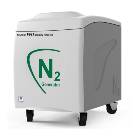
VICI DBS MISTRAL User manual

1
MISTRAL GAS STATION
USER MANUAL www.vicidbs.com
Version 2.00.0000
TECH SUPPORT
Europe, Asia, Africa, Australia & New Zealand:
techsupport@vicidbs.com
USA, Canada, Central & South America:
techsupportus[email protected]
Italy
service@vicidbs.com
VICI AG INTERNATIONAL
Parkstrasse 2
CH-6214 Schenkon
Switzerland
tel: + 41 41 925-6200
fax: + 41 41 925-6201
web: www.vicidbs.com
APPLICABLE MODELS
This manual is applicable to the following models:
• Mistral Gas Station
Version 2.00.0000

1
MISTRAL GAS STATION
USER MANUAL www.vicidbs.com
Version 2.00.0000
TABLE OF CONTENTS
1. VERSION HISTORY................................................................................................................................ 2
2. INTRODUCTION.................................................................................................................................... 3
2.1. Symbol Denitions...............................................................................................................................3
3. SAFETY.................................................................................................................................................. 4
3.1. Personal Safety Instructions.................................................................................................................4
3.2. Instrument Safety Instructions ............................................................................................................4
4. SPECIFICATIONS................................................................................................................................... 5
5. PRESENTATION OF DEVICE ................................................................................................................. 6
5.1. Front View............................................................................................................................................6
5.2. Back View............................................................................................................................................6
5.3. Lateral View.........................................................................................................................................7
5.4. Connections ........................................................................................................................................7
5.5. Power Supply Settings ........................................................................................................................8
5.6. Transport and Storage ........................................................................................................................8
6. SCHEMATICS......................................................................................................................................... 9
6.1. Fluidics.................................................................................................................................................9
6.2. Electrical............................................................................................................................................ 10
7. STARTING THE GENERATOR ......................................................................................................... 11-13
8. SOFTWARE.......................................................................................................................................... 14
8.1. Overview of the Menus.....................................................................................................................14
8.2. Parameters ........................................................................................................................................14
8.3. Diagnostic .........................................................................................................................................15
9. OPTIONAL EXTERNAL TANK.............................................................................................................. 15
9.1. Size of Tank .......................................................................................................................................15
9.1.1. Tank Size Calculation................................................................................................................16
9.2. Where to Get the Tank......................................................................................................................16
9.3. Recommended Set-Up......................................................................................................................16
10. ALARMS & PRE-ALARMS .................................................................................................................. 17
10.1. Pre-Alarms.......................................................................................................................................17
10.2. Alarms .............................................................................................................................................17
11. TROUBLESHOOTING......................................................................................................................... 18
12. MAINTENANCE................................................................................................................................. 19
12.1. 4000h Maintenance ......................................................................................................................... 19
12.2. 8000h Maintenance......................................................................................................................... 19
13. SPARE PARTS ............................................................................................................................... 19-20
2
MISTRAL GAS STATION
USER MANUAL www.vicidbs.com
Version 2.00.0000
1. VERSION HISTORY
VERSION DATE COMMENT/CHANGE
1.00.0100 01/10/2017 Layout and initial release, VICI DBS
1.01.0000 03/29/2019 Update
2.00.0000 07/13/2021 New layout, images and graphics, VICI Gig Harbor Group

3
MISTRAL GAS STATION
USER MANUAL www.vicidbs.com
Version 2.00.0000
2. INTRODUCTION
The VICI DBS® Mistral Gas Station includes an oil-free air compressor and delivers a continuous ow of
nitrogen with a purity of 99.5% at a rate of 25 L/min and simultaneously 35 L/min of ltered air.
The Mistral Gas Station uses pressure swing adsorption technology (PSA) to remove oxygen, carbon dioxide
and water from compressed air. The resulting pure nitrogen is ideal for laboratory applications like LC-MS and
other applications requiring inert gas.
2.1. Symbol Denitions
SYMBOL DESCRIPTION
General warning. Caution is necessary when operating the device or control
close to where the symbol is placed, or to indicate that the current situation
needs operator awareness or operator action in order to avoid undesirable
consequences.
The manual must be consulted in all cases where this symbol is marked on
the device.
Risk of asphyxia. Caution is necessary when operating the device in a not
sufciently ventilated area.
Oxidant material. Caution is necessary due to the presence of oxidant material.
WEEE symbol. When discard this product, it must be sent to separate collection
facilities for recovery and recycling.
Fuse. Notify replaceable fuse place.
OR
OR
OR

4
MISTRAL GAS STATION
USER MANUAL www.vicidbs.com
Version 2.00.0000
3. SAFETY
3.1. Personal Safety Instructions
When using your Mistral Gas Station, basic safety precautions should always be followed, including
the following:
• The quantity of dust in the ambient Air can be very different from one place to another.
We recommend to replace the dust lters every 4000H. In some dusty areas, this
maintenance need to be performed more frequently.
• Clogged dust lter may damage the device or give a bad Nitrogen quality.
• The power supply main cable connector is the disconnect device in case of
emergency, it must be easily accessible at any time.
• If the Mistral Gas Station is used in a way not specied by VICI DBS, the
protection provided by the equipment could be compromised.
3.2. Instrument Safety Instructions
• The Mistral Gas Station is a nitrogen generator. Do not let it run with the outlet open to
the air in a low volume room.
• The increase of the Nitrogen (and decrease of oxygen) may cause human disease.
It is the responsibility of the user to check if the room is appropriate or if an O2
measurement is necessary.
• The Mistral Gas Station rejects oxygen as waste.
• Oxygen ratio in the air could change around the device in a low volume or not
sufcient ventilated room.
• If fuel gases are present around, their explosive or ammable limits could be
affected. It is the responsibility of the user to check if the room is appropriate or
if an O2 measurement is necessary.

5
MISTRAL GAS STATION
USER MANUAL www.vicidbs.com
Version 2.00.0000
4. SPECIFICATIONS
MISTRAL GAS STATION
Nitrogen ow rate L/min 25 @ 5.5 barg (80 psig)
Air 1 - ow rate L/min 35 @ 5.5 barg (80 psig)
Nitrogen purity >99.5%
Dewpoint oC (oF) -40 (-40)
Outlet pressure barg (psig) 7 (100)
Technology Carbon molecular sieve
Warm up time (minutes) 20
Electrical supply 110-120V 60 Hz / 220-240V 50Hz
Power consumption (watts) 2700
Noise level 55 dBA @ 1 meter
Dimensions mm (in) 482W x 641H x 1235D (18.9W x 25H x 48D)
Weight kg (lbs) 110 (243)
Shipping dimensions mm (in) 550W x 800H x 940D (21.6W x 31.4H x 37D)
Shipping weight kg (lbs) 141 (311)
Operating temp oC (oF) 15 to 35 (59 to 95)
Outlet connection 2 x 6mm OD compression or 1/4”
Certication CE, FCC, MET (UL and CSA compliant)
MODELS & SPECS

6
MISTRAL GAS STATION
USER MANUAL www.vicidbs.com
Version 2.00.0000
5. PRESENTATION OF THE DEVICE
5.1. Front View
Command Buttons (x3)LED Indicator Lights
Backlit Display
5.2. Back View
Relay Alarm
Outlet Compressor
Box Cooling System
Dust Silencer Filter
Outlet Water
Purge
Outlet N2
with Valve
Air Power Supply
and Fuses
Nitrogen Power
Supply and Fuses
Outlet Air
with Valve
Fuse Holder F3

7
MISTRAL GAS STATION
USER MANUAL www.vicidbs.com
Version 2.00.0000
Line Pressure
Flow Set
Pressure
Air Outlet
Pressure
5.3. Lateral View
5.4. Connections
Power Supply: C-20 Outlet N2 with Valve: G1/4” female
Outlet Water Purge: Ø10mm tube Relay Alarm: 2 pos universal Mate-N-Lock
connector female
N2 Outlet
Pressure
Service Box

8
MISTRAL GAS STATION
USER MANUAL www.vicidbs.com
Version 2.00.0000
5.5. Power Supply Settings
The current power supply setting of the generator is indicated on the ID Sticker at the back of the generator.
The MISTRAL GAS Station standard setting is 210-230V /50-60Hz.
If other voltages are required, this should be done when ordering. In this case a transformer will be installed
to transform internally the requested voltage to 110-115 V /50-60Hz. Below you will nd the list with possible
voltage- and frequency settings. In any case the voltage of the power supplied must stay within +/- 10% of the
nominal value.
VOLTAGE SETTING FREQUENCY FUSE F3 (5X20 OR 6.3 x 32 mm) COUNTRY
110-120 VAC 60 Hz 20 A Japan/U.S.A.
220-240 VAC 50 Hz 10 A Korea/Europe
Please see service manual for the connection of the transformer. General earth connection is done via power
supply main cable.
5.6. Transport and Storage Conditions
Temperature Minimum 4ºC (39ºF), Maximum 45ºC (113ºF)
Humidity Inferior to 90% Rh, non-condensing
Shocks and vibrations during transport Shocks <1g; Vibrations <0.2g/5Hz
Instruments position Horizontal
The above mentioned values are considered for an instrument transported in its original new packing.
The device contains castors to be moved easily. Use the breaks to make the device stable. The Mistral Gas
Station could be elevated from any points under the chassis base.
Recommendations for Transport
When the instrument is shipped back to the factory for recalibration or repair, the Mistral Gas Station should
be packed in its original packing with the inlets and outlets protected against any accidental penetration of
dust or particles of the package.

9
MISTRAL GAS STATION
USER MANUAL www.vicidbs.com
Version 2.00.0000
6.1. Fluidics
6. SCHEMATICS
System:
Schematic no:
Date:
Created:
Checked:
Released:
THIS DOCUMENT AND THE INFORMATION WHICH
IT CONTAINS SHALL NOT BE USED, EXPLOITED
OR SOLD, AND SHALL NOT BE REVEALED OR
DISCLOSED TO OTHERS WITHOUT THE EXPRESS
WRITTEN PERMISSION OF VICI. THIS DOCUMENT
SHALL REMAIN THE PROPERTY OF VICI AND
SHALL BE RETURNED UPON DEMAND.
R
Rev.:
Sheet:
By:
Description:
ECN no:
Mistral Evolution Gas Station
air flow diagram 11.06.21 SBU
1
1/1

10
MISTRAL GAS STATION
USER MANUAL www.vicidbs.com
Version 2.00.0000
6.2. Electrical
System:
Schematic no:
Date:
Created:
Checked:
Released:
THIS DOCUMENT AND THE INFORMATION WHICH
IT CONTAINS SHALL NOT BE USED, EXPLOITED
OR SOLD, AND SHALL NOT BE REVEALED OR
DISCLOSED TO OTHERS WITHOUT THE EXPRESS
WRITTEN PERMISSION OF VICI. THIS DOCUMENT
SHALL REMAIN THE PROPERTY OF VICI AND
SHALL BE RETURNED UPON DEMAND.
R
Rev.:
Sheet:
By:
Description:
ECN no:
Mistral Evolution Gas Station
electrical diagram 11.06.21 SBU
1
1/1

11
MISTRAL GAS STATION
USER MANUAL www.vicidbs.com
Version 2.00.0000
• Read the Operations Manual carefully.
• Do not place the Mistral Gas Station on a sloping area, use the wheel breaks.
• Make sure the voltage setting is correct
• The power supply main cable connector is the disconnect device in case of emer-
gency, it must be easily accessible at anytime.
7. STARTING THE GENERATOR
Connect the Mistral Gas Station to the power line.
1. Close the On/Off (O/I) valve placed at the back side of the device
2. Connect the outlet to your application
3. If you use an intermediate buffer tank, please look at the specic chapter. Connect the outlet water
condensate of the Mistral Gas Station to an external water tank
4. Turn the generator on (switch in back).
5. The Air part will run automatically and constantly when switched on
6. The Nitrogen part will run according to the program/command entries
7. The following display will come up:
AIR NITROGEN

12
MISTRAL GAS STATION
USER MANUAL www.vicidbs.com
Version 2.00.0000
9. The following display will come up (example):
8. Press the “Menu” button and scroll through the program until you get to the “Parameter” menu. Press the
“Select” button:
Go through the sub menus and select the parameters. The different possible settings are explained in the
specic chapters
10. Now press 2 times the “Exit” button to come back to the initial screen
11. Press the “Start” button
12. The compressors will start and the pressure will increase up to 8 bar (this pressure value is pre-set at the
factory). IMPORTANT: Do NOT change this pre-set value!

13
MISTRAL GAS STATION
USER MANUAL www.vicidbs.com
Version 2.00.0000
13. If you need another pressure setting, then open the service box at the back side of the generator.
14. Turn the tap clockwise to increase the pressure or counter-clockwise to decrease the pressure.
15. Once the pressure is set, open the ON/OFF valves at the back side of the generator.
16. The generator will need several hours before it will reach the correct Nitrogen purity and Air quality.

14
MISTRAL GAS STATION
USER MANUAL www.vicidbs.com
Version 2.00.0000
8. SOFTWARE
8.1. Overview of the Menus
The Mistral Gas Station has the following menus:
PARAMETER Used to set the different parameters
CONFIGURE Only available to trained individuals; password protected
DIAGNOSTIC Used to see the different values of the sensors
ALARM HISTORY Shows the history of alarms
SET CLOCK Sets the clock
SPECIAL FUNCTIONS Enter a password to access specic menus
8.2. Parameters
ITEM DESCRIPTION OPTIONS/RANGE DEFAULT
Pressure Unit Sets desired unit of measure for pressure bar/kPa/psi bar
Temperature Unit Sets desired unit of measure for temperature ºC/ºF ºC
Flow Unit Sets desired unit of measure for ow rate L/min - ft3/min L/min
Auto Start Choose to automatically start production upon
powering on or not
Yes/No No
Display Contrast Sets desired contrast of display 1-10 5
Beeper Sets alarm beep on/off Yes/No Yes
Pre-Alarms in List Choose to see pre-alarms in alarm history or not Yes/No No
External Tank Activated only for external tank. Using this mode,
the generator will stop when tank reaches “P.
Max. Tank” pressure and will start when pressure
drops below minimum level of “P. Min. Tank”
Yes/No No
P. Min. Tank Sets minimum pressure reached in external tank
to restart the generator
1-8 1 bar
P. Max. Tank Sets maximum pressure reached in external tank
to stop the generator
6-9 8 bar
Standby Purge Restart every 24 hours if the generator is in
standby, in external tank mode
Yes/No No

15
MISTRAL GAS STATION
USER MANUAL www.vicidbs.com
Version 2.00.0000
8.3. Diagnostic
ITEM DESCRIPTION
Temperature Shows the instant temperature in the cabinet
Outlet Pressure Shows the instant outlet pressure
Int. Tank Pressure Shows the instant pressure in the internal reservoir
Comp. Work Time Shows the work time of the compressor
Service 4000h Shows the work time for the 4000h service
9. OPTIONAL EXTERNAL TANK
In some situation, the LC-MS devices do not need the full ow of Nitrogen. This is also the case if the LC-MS
stops. In such situation it does not make sense to have the Mistral Gas Station run continuously and throw
away the produced Nitrogen.
The Mistral Gas Station is able to handle an external tank management. The Mistral Gas Station will run until
the high set pressure (P Max Tank) is reached. Then the Mistral Gas Station will stop until the low set pressure
(P Min Tank) is reached.
9.1. Size of Tank
The size of the tank is very critical. If at the same time...
• the tank is to small
• the pressure difference = (P Max Tank)- (P Min Tank) is small
• the requested ow is high
...then the Mistral Gas Station will start and stop too often and this will damage the compressors of the device.
That’s the reason, once the Mistral Gas Station has stopped, he will not restart before 300s (5 minutes).

16
MISTRAL GAS STATION
USER MANUAL www.vicidbs.com
Version 2.00.0000
9.1.1. Tank Size Calculation
Given:
• The nitrogen consumption is 30 L/min
• The LCMS needs 7 barg (101.5 psig) pressure
...the max usable pressure of the Mistral Gas Station is 9 barg (130.5 psig). This mean that the max pressure
difference is our example is 2 barg (29 psig).
You’ll need to store at least the requested Nitrogen for the 5 minute stops of the compressors (30 NL/min x 5
min) = 150 L atm.
As we can have 2 barg (29 psig) pressure difference, the requested volume will be 150 L / 2 = 75 L
This is the minimal size tank requirements. In order to save the compressor life time, we recommend to
oversize the tank by a factor of 3.
In this example, the right size of the tank will be around 225 L
9.2. Where to Get the Tank
As the size of the tank will be large for application and in addition legislation is different from one country to
another, DBS doesn’t sell this article and let the customer purchases it locally.
Note: The tank must be compatible with pressures up to 10 bar and certied (CE marked for Europe).
Using a non-certied external tank may be dangerous and may cause human disease.
Tubing and ttings must also support the requested pressure.
9.3. Recommended Set-Up
As the size of the tank will be large for application (and legislation is different from one country to another),
VICI DBS does not sell this product allowing the customer to purchase it locally.
Relief valve set
below the max
pressure allowed
by the tank
Manometer
(Pressure of the
application)
Manometer
(Pressure of the
application)
External certied
air buffer vessel
LCMS Application

17
MISTRAL GAS STATION
USER MANUAL www.vicidbs.com
Version 2.00.0000
10.2. Alarms
Do stop the device.
ITEM DESCRIPTION
Temperature The temperature inside the cabinet is too high
Int. Tank Pressure Min. The pressure in the internal reservoir is too low
Int. Tank Pressure Max. The pressure in the internal reservoir is too high (10 bar) and the relief valve do
not work. Check the relief valve. The High pressure compressor may not work.
Call the service line.
P. Max Outlet The outlet pressure is too high. Check if the output tting is free. If it is all right,
call the service.
WT CMP The compressors must be changed.
SRV 4000 The lter must be changed. See service manual section on 4000 h service kit.
10. ALARMS & PRE-ALARMS
10.1. Pre-Alarms
Precursors of the alarms – they Do not stop the device.
ITEM DESCRIPTION
Temperature The temperature inside the cabinet is over the maximum limit. Check if the room
temperature respects the specications and if there is enough space in the rear side of
the unit for the ventilation. Otherwise, remove the right panel of the machine and the
cabinet panel and check if all the fans are working. If it is all right, call the service. Press
the reset button.
P. Min Internal
Tank
The pressure in the internal reservoir is less than the lower limit. Call the service. Press
the reset button.
WT CMP The compressors must be changed. Call the service. Press the reset button.
SRV 4000 The lter must be changed. See the maintenance section of this manual relatively to
the 4000 h service kit. Call the service to order the new kit. Press the reset button.

18
MISTRAL GAS STATION
USER MANUAL www.vicidbs.com
Version 2.00.0000
• Please refer to the service manual before self-servicing Mistral Gas Station.
• Please contact our service department before self-servicing.
• If the device is self-serviced without an agreement with VICI DBS Service
Department, the warranty will be void.
11. TROUBLESHOOTING
PROBLEM MAIN POTENTIAL CAUSE CORRECTIVE ACTION
Temperature: The
temperature inside the
compressor cabinet is
too high
The Outlet compressor box cooling
system is blocked or the back side of the
device is next to a wall and the hot air
cannot go out.
Put the device in another place.
The outside temperature is too high and
do not cool the compressors
The compressors are overheating Check and eventually replace the
compressors
Int. tank pressure min.:
The pressure in the
internal reservoir is too
low.
The dust lters are clogged Change the foam dust lters.
The compressors do not gives enough
pressure
Check and eventually replace the
compressors
Leakage Check a leakage.
Int. tank pressure max.
The pressure in the
internal reservoir is too
high.
The relief valve is not working properly
and High pressure compressor is not
working
Check and eventually replace the
compressors / and the relive valve
WT CMP Standard Life time of compressors has
expired
Perform the preventive compressor
change
SRV 4000 Standard Life time of dust lters has
expired
Perform a maintenance
Alarm EEP failure:
Failure of the static
memory
Call the service department

19
MISTRAL GAS STATION
USER MANUAL www.vicidbs.com
Version 2.00.0000
12.1. 4000h Maintenance
Every 4,000h the intake air lter, outlet silencer and cartridges must be replaced.
12. MAINTENANCE
DB-10619 Maintenance kit 4000h for Mistral
Gas Station includes:
1 - white silencer
3 - blue silencers
3 - cartridges
12.2. 8000h Maintenance
Every 8,000-10,000h the compressors must be replaced.
DB-EVO-002 OF-302 Air compressor (hybrid and gas station)
DB-EVO-010 OF-312 Air compressor (air)
DB-EVO-011 OF-332 Air compressor (nitrogen)
13. SPARE PARTS
VICI DBS P/N DESCRIPTION
DB-EVO-001 Complete Heat Exchanger
DB-EVO-003 Resin Inlet Filter
DB-H200-041 Display for NM series 2/PG series 3
DB-H200-042 Display membrane
DB-WN2-003 Manometer
DB-EVO-007 Plastic Cover Kit
DB-EVO-008 Inlet Power Filter 110
DB-EVO-009 Mistral Evo Main Board
DB-EVO-010 OF-312 Air Compressor (air)
DB-EVO-011 OF-332 Compressor, high pressure
DB-EVO-012 Silencer white
Table of contents
Other VICI DBS Portable Generator manuals

VICI DBS
VICI DBS MISTRAL EVOLUTION 10 User manual

VICI DBS
VICI DBS MISTRAL EVOLUTION HYBRID User manual

VICI DBS
VICI DBS PG Plus Rack 100 User manual

VICI DBS
VICI DBS PCB 1500 User manual

VICI DBS
VICI DBS NM PLUS User manual

VICI DBS
VICI DBS HK PLUS Series Instruction manual

VICI DBS
VICI DBS GT ULTRA ZERO AIR GENERATOR User manual

VICI DBS
VICI DBS NM PLUS Series User manual

VICI DBS
VICI DBS MINI WHISPER User manual

VICI DBS
VICI DBS HP PLUS Series User manual