TLT-Moto 4010 User manual

User Manual for CAN-Switchbox
from serialnumber (S/N) 900
(Order-Code #4010)
Looking for German manual?
Visit our hompage
www.tlt-moto.de
Thank you for coosing the TLT-Moto CAN-Switchbox, which is assembled in
Germany. This product is continually tested and developed of engineers and
technicians who also drive motorcycle.
User Manual for CAN-Switchbox Seite 1 / 12

Please read and follow these instructions when mounting and connection the CAN-
Switchbox.
1. Function of the CAN-Switchbox
The CAN switch box is able to simulate and replace the original handlebar fittings as
well as the speedometer on the current Sportster®, Dyna® and Softail® models
with HD-LAN.
A step-by-step conversion is also possible by replacing the handlebar fittings with
other buttons in the first step and later the original speedometer. If, for example,
the HD speedometer is no longer available, this is automatically recognized by the
CAN switch box and our box begins to simulate the speedometer. It sends all the
necessary signals to the on-board electronics and the BCM does not recognize any
difference to the original version. This means that there are no error messages and
the motorcycle can be operated with a third-party speedometer.
It is important here that all functions that are given in the Harley® original version
are also retained with our CAN switch box. Most custom conversions try to achieve
a "clean" condition. Here comes the compact one The design of the box with only
70x50x20mm is very opposed. It can actually be installed at any point in the
motorcycle, preferably in the frame triangle behind the steering head bearing. This
would have the advantage that you are directly at the original connection point of
the fittings. The connector can thus be used directly, preferably from the right-hand
side.
Please note that with the CAN switchbox, the wiring harness can remain completely
unchanged and does not have to be laboriously converted. With the optionally
available cable kits, not even a plug needs to be changed. Everything remains
ORIGINAL.
This CAN switchbox version is suitable for both HD keyless models and HD CAN
motorcycles with a conventional ignition lock.
2. Connection
The connection of our box is not difficult, but it should be done by an expert. One
side of all push-button and switches has to be connected to ground and the other
side has to be connected to the CAN-Switchbox, please take a look of the schematic.
The outputs of the CAN-Switchbox switch +12 volts. The outputs for display LEDs
[R7 - R12] switch to ground (GND). See also the wiring diagram and the pin
assignment.
The power supply for the high-power outputs (supply line [M2]) should be
connected to +12 volt from the ignition.
All associated power outputs are also located on the M bar [M3-M10].
For proper function, a good connection to the vehicle mass is very important, so at
least one of the two hexagon threaded bolts should be firmly connected to ground.
2.1 Wiring Diagram
The exact connection name of the CAN switch box is described in more detail in the
following table. The pin assignment is shown in figure 2.1 and the following table.
User Manual for CAN-Switchbox Seite 2 / 12

Terminal Block Left (Input)
Pin-Nummer Function Connection
L1 - GND vehicle mass (GND)
push-button ground inputs
L2 – turn left Blinker Links on / off push button turn left
L3 – turn right Blinker Rechts on / off push button turn right
L4 - start Start des Motors push button start
L5 – kill/run ignition off / on push button kill/run
L6 - clutch clutch clutch
L7 - break brake push button brake
L8 – high beam high beam on / off push button high beam
L9 - horn Horn push button horn
L10 – trip Trip push button trip
L11 - flash flasher push button flaher
L12 - EMC warning flasher push button EMC
Terminal Block Left (low power output)
Pin-Nummer Function Connection
HD-Connector
R1 - GND GND [22B-1] Ground (bk or bl tlt-color
R2 - +12V +12 Volt battery [22B-1] +12V (red tlt-color)
R3 – CAN L CAN_Low [22B-1] CAN Low (green tlt-color)
R4 – CAN H CAN_High [22B-1] CAN High (yellow tlt-color)
Tacho
R5 – speed out external speedometer Output external Speedometer
R6 – RPM out external RPMmeter Output external RPM-meter
LED Ground Output
R7 – turn left LED turn left output only for LED (switched to GND)
R8 - turn right LED turn right output only for LED (switched to GND)
R9 – ABS LED ABS output only for LED (switched to GND)
R10 – neutral LED neutral output only for LED (switched to GND)
R11 – oil LED oil output only for LED (switched to GND)
R12 – high beam LED high beam output only for LED (switched to GND)
Terminal Block middle (high power output)
Pin-Nummer Function Connection
M1 - GND GND vehicle mass (GND)
+
1
2
V
H
i
g
h
P
o
w
e
r
O
u
t
p
u
t
s
M2 - +12 Volt Power +12V input for M3 - M9 Please connect with ignition
M3 – Turn Left Power Power Output 36 Watt output turn left indicator l.
M4 – Turn Right Power Power Output 36 Watt output turn right indicator l.
M5 - ABS Power-Out Power Output 36 Watt output ABS indicator light
M6 – Oil Power-Out Power Output 36 Watt output Öl indicator light
M7 – Neutral Power Power Output 36 Watt output neutral indicator light
M8 - High Beam Power Power Output 36 Watt out. high beam indicator light
M9 - reserved
M10 – reserved
M11 – Trip Switch Out Switched to ground original menu/trip switch out
M12 – RUN RUN [22B-2] Energie Stop
User Manual for CAN-Switchbox Seite 3 / 12
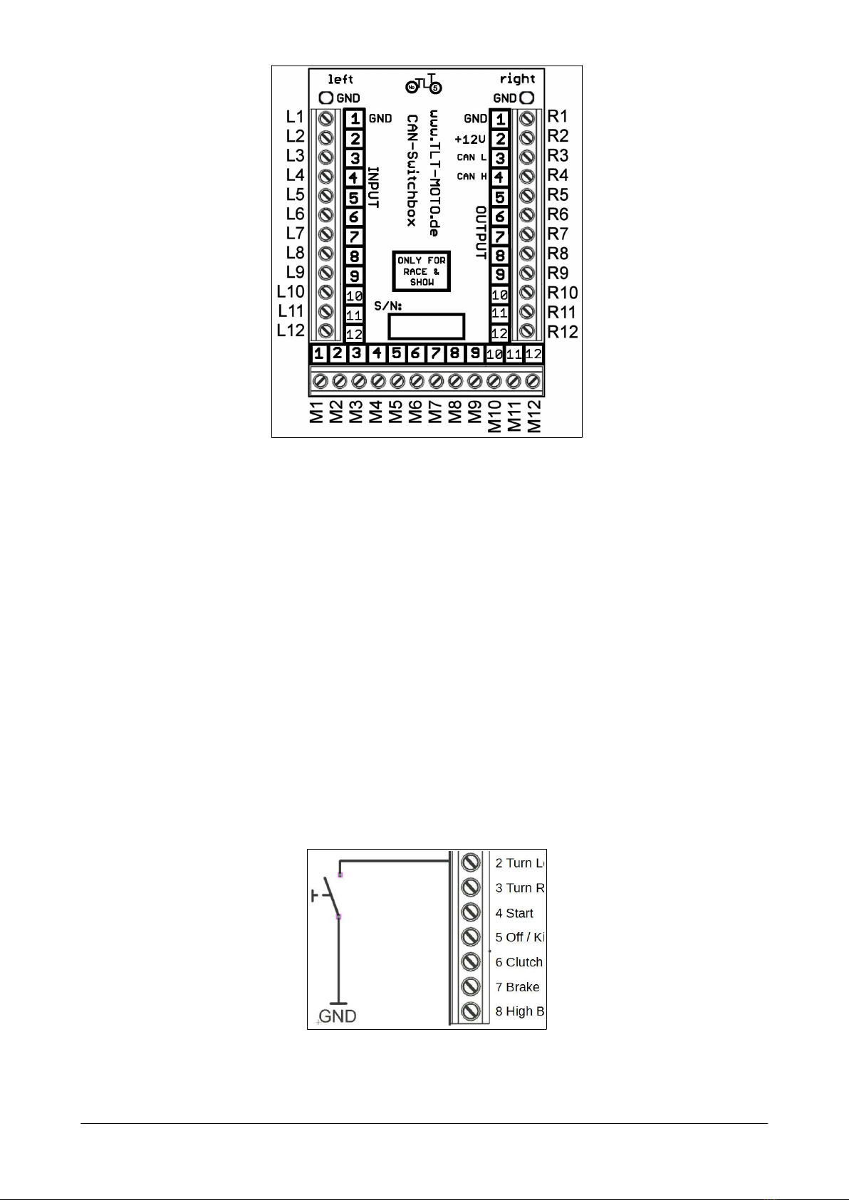
Figure 2.1 pin assignment
2.2 CAN-Switchbox connection
The contacts [R1] (GND), [R2] (+ 12V), [R3] (CAN-Low), [R4] (CAN-High) and
[M12] (RUN) connect the CAN-Switchbox to the motorcycle. These signals are
located on the connectors for the original handlebar fittings. A corresponding set
Connection plug is available from TLT-Moto (see Figures 4.1 and 4.2). Will the
motorcycle switched off, the CAN switchbox switches itself off after approx. 30
seconds (the Power LED goes out). The CAN switchbox switches itself when
required or manually with the KILL / RUN button.
2.3 push-button connection
As already mentioned, the buttons are connected to the corresponding input
of the CAN switch box connected. One pole of the push button is connected to
the input of the box and the other pole with connected to the ground (GND) of
the vehicle. The polarity of the button does not have to be be respected.
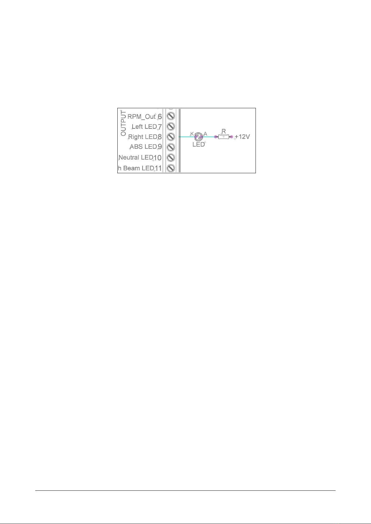
Figure 2.3 connection of the push-button
User Manual for CAN-Switchbox Seite 4 / 12
2.4 Connection of the LED indicator lights
The CAN switchbox switches ground (GND) for the LED lights. These are the
outputs [R7] to [R12]. See also chapter 2.6.
Thus, the + pole (anode) of the control LEDs must be connected to +12 volts and the
cathode to the corresponding output of the CAN switch box. It is placed on the
control LED by the CAN switch box GND. With 12 volt LEDs no series resistor is
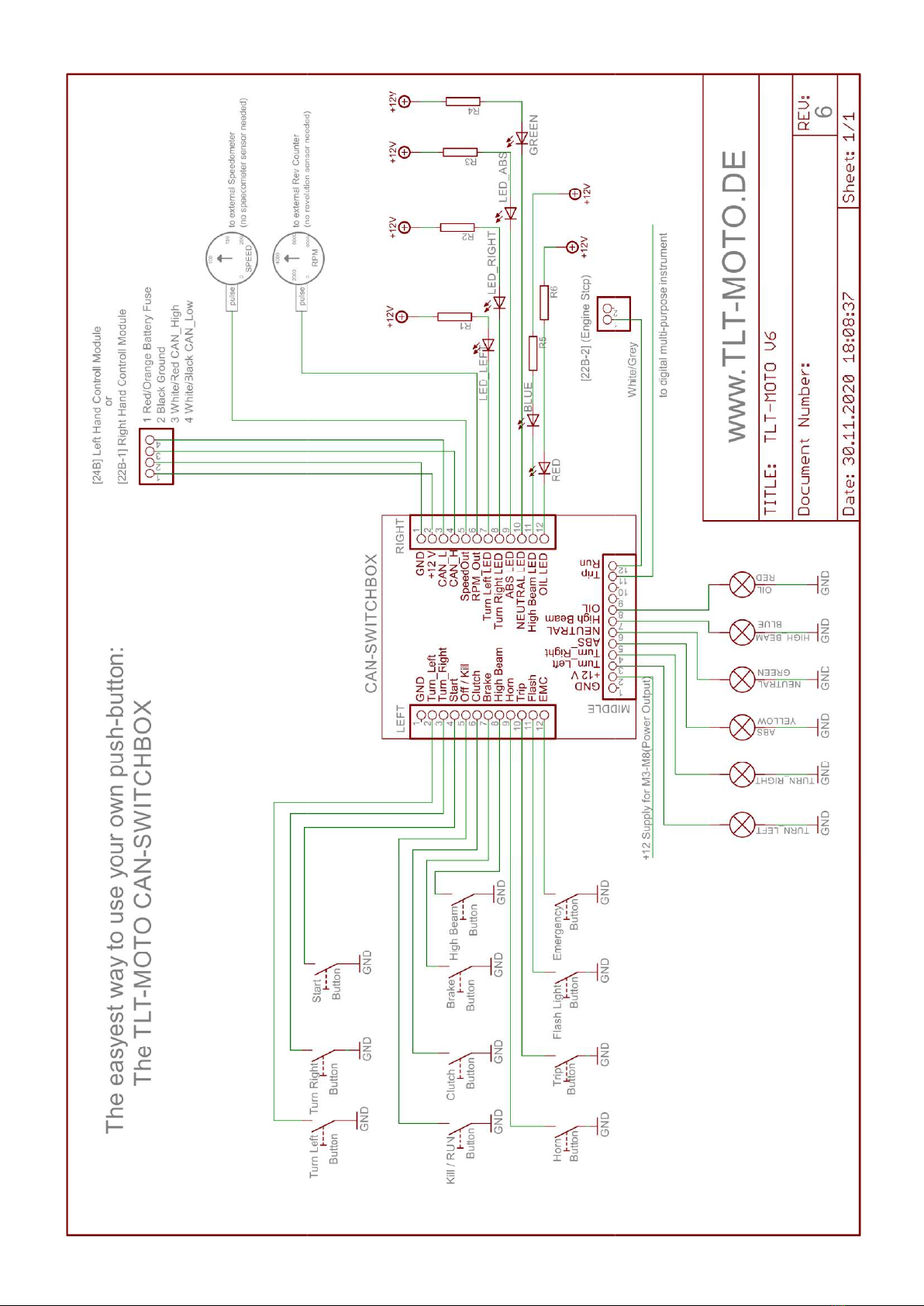
necessary. Otherwise, a series resistor, see Figure 2.4, is required. Please take care
only that all outputs [R5 - R12] may not be loaded with more than 100 mA.
Figure 2.4 Connection of LED indicator lights
User Manual for CAN-Switchbox Seite 5 / 12

2.5 Connection of the Turn Signals
The + pole of the turn signals is connected to the corresponding output [M3 + M4]
of the CAN switchbox. The other pole must again be connected to ground (GND) of
the vehicle. The connection of 12 volt LED turn signals is possible without load
resistor. Note that these outputs are supplied by a common supply line [M2]. These
should be connected + 12V from the ignition.
Figure 2.5 Connection of turn signals and indicator lights
2.6 Exchange of the original HD speedometer with the
CAN-Switchbox
If, for example, only the original speedometer unit is to be replaced, the CAN
switchbox can be connected in its place, as can be seen in Figure 2.7.
Figure 2.6 Extract from the circuit diagram of a Dyna® model 2012
Figure 2.6 shows the connector [39B] from the original speedometer and which
lines are to be connected where. The connection to [22B] is also shown in the
connection diagram on the following pages. We also offer two different cable
connection kits as optional accessories so that the original HD cable harness does
not have to be destroyed.
User Manual for CAN-Switchbox Seite 7 / 12
2.7 Connection of a new speedometer or rev counter, e.g. from
motogadget®
The CAN-Switchbox provides a pulse signal for the external tachometer
[R5] (e.g. motoscope®-mini the white line) and also a pulse signal for a RPMmeter
[R6] (e.g. motoscope®-mini the yellow line). Thus, no pulser must be installed.
The CAN-Switchbox provides a clocked ground (GND). This signal is the same as
that of most speedometer accessories (eg motoscope® or Chromclassic® from
motogadget®). In the rarest cases, a pull-up resistors must be connected to the
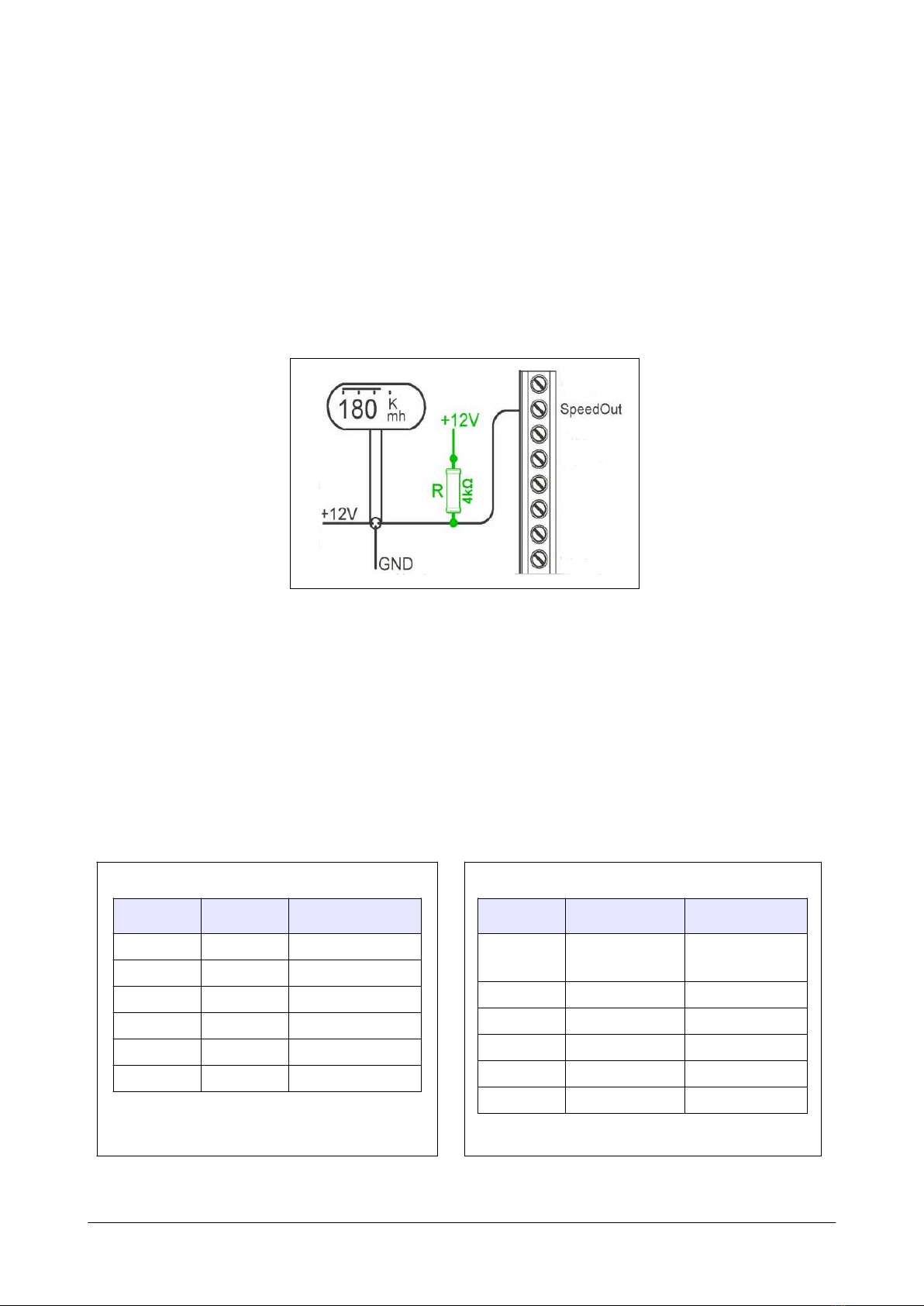
operating voltage and the outputs SpeedOut or RPMOut (see Fig. 2.6) so that the
tacho interprets the signal correctly.
Figure 2.6 connection without resistor or with a ca. 2-4 kΩ Pull-Up
If you do not want to activate the menu of the new speedometer with an additional
button, the trip input of the speedometer (e.g. motoscope®-mini the green line) can
be connected to [M11] of the CAN-Switchbox.
Even the 6-fold LED bar from Thunderbike or the motoscope®-mini connect is no
problem.
Example ways:
Thunderbike 6x LED-bar
color funktion CAN-Switchbox
w
h
i
t
e
t
u
r
n
l
e
f
t
R
7
g
r
a
y
/
p
i
n
k
t
u
r
n
r
i
g
h
t
R
8
b
l
a
c
k
a
b
s
R
9
g
r
a
y
n
e
u
t
r
a
l
R
1
0
b
l
u
e
o
i
l
R
1
1
g
r
e
e
n
h
i
g
h
b
e
a
m
R
1
2
connect brown, yellow, pink, red, violett,
red/blue to switched +12V
motosign-mini
color function CAN-Switchbox
red turn left
or right
M3 + M4 via
two diodes
b
l
u
e
a
b
s
M
5
w
h
i
t
e
n
e
u
t
r
a
l
M
6
b
r
o
w
n
o
i
l
M
7
g
r
e
e
n
h
i
g
h
b
e
a
m
M
8
o
r
a
n
g
e
g
r
o
u
n
d
/
M
a
s
s
e
M
1
o
r
g
r
o
u
n
d
connect [M1] from our box or ground to
orange, yellow, black and violett
User Manual for CAN-Switchbox Seite 8 / 12

2.8 Start and change the CAN-Switchbox mode
The function of the CAN-Switchbox should correspond to the handling of the
keyless version and also that of the original HD control with ignition lock. Therefore
it starts in KILL-Mode, this is indicated optically by the output LED flashing very
quickly (approx. 4Hz). If the CAN-Switchbox is in this mode and no button is
pressed, it goes to sleep again after approx. 30 seconds and switches off.
By pressing the KILL / RUN button, the CAN switchbox changes to RUN-Mode,
the output LED of the box goes out and the BCM activates the ignition.
Pressing the KILL / RUN button again deactivates the ignition of the motorcycle,
the CAN switchbox switches back to KILL-Mode. The output LED flashes again
very quickly and after approx. 30 seconds the motorcycle switches off again.
2.9 Special functions and keyboard shortcuts
When converting the original handlebar fittings usually the number of controls,
buttons are reduced. Therefore, some buttons have additional functions so that you
can emulate all original functions even with a total of 6 buttons.
Thus, the following is possible :
Left-Hand-Controll-Module: turn left, high beam, horn
Right-Hand-Controll-Module: turn right, KILL/RUN (+Start), Trip
L ist of I mplemented A dditional F unctions :
transport mode: simultaneous pressing of both turn signals
hazard lights: with the handbrake held, press both indicators at the same
time
KILL/RUN button: by briefly pressing the KILL/RUN button you switch between
KILL and RUN mode. In RUN mode, the ignition is switched
on and the low beam is switched on lights up and the fuel
pump works. In KILL mode, the output LED on the CAN
switch box flashes very fast (approx. 4Hz). The motorcycle
switches off the ignition and everything turns off completely
after a while. Should the If the engine has been running
before, it will stop
Start engine with Kill/RUN: long press the KILL/RUN button (approx. 2-3 sec.)
simulates pressing the start button and the engine starts.
Trip/Menu button simulation: If the speedometer has been replaced, the so-
called Menu button of the new speedometer via the CAN
switchbox be operated. For example just the green line of the
Connect the mg-scope-mini to the [M11] of the CAN
switchbox. So is with original handlebar fittings by pressing
the trip the menu button is pressed.
Attention, this only works with menu buttons after Switch
ground.
User Manual for CAN-Switchbox Seite 9 / 12

3 What do the LEDs of the CAN-Switchbox mean?
There are three LEDs on the board to facilitate connection of the CAN-Switchbox.
At the top of the board is the Power-LED, which lights up as soon as the CAN-
Switchbox is active (Figure 3.1).
The Input-LED is located on the top left of the CAN switch box. It lights as soon as
one of the numerous inputs is connected to ground, but only if the box is connected
to the BCM. This means that the input LED is not lit although, for example, the trip
input is grounded, but the CAN is not connected or is connected incorrectly.
On the right is the Output-LED, which is alternately on / off only when the turn
signal is switched on to the beat of the original turn signals. If the output LED
flashes very fast, the CAN-Switchbox is in kill / stop mode, the ignition is off.
Figure 3.1 CAN-Switchbox LEDs
4 Optional Accessories
To facilitate the connection to the existing motorcycle electronics, we offer a cable
connection kit. These kits are optional and must be ordered separately. The
following pictures show the two available cable connection kits for direct connection
to the original existing HD connectors.
Fig. 3.1 Handlebar-Cable-Kit [22B] Fig. 3.2 Speedometer-Cable-Kit [39B]
(Order-Code #3001) (Order-Code #3002)
User Manual for CAN-Switchbox Seite 10 / 12

5 Technical Data
length / width / height: 70 mm / 50 mm / 20 mm
weight: ca. 35 g
mounting holes: 2 x M3 10 mm
current: ca. 34 mA (Logik), standby ca. 9 µA
operating voltage: 9 – 18V
operating temperature: -20°... + 80°C
6 Disclaimer
THE CAN SWITCHBOX SHOULD NEVER BE OPENED OR CHANGED, IN
THIS EVENT WILL VOID ANY WARRANTY. TLT-MOTO ASSUMES NO
LIABILITY FOR DIRECT OR INDIRECT DAMAGE OR CONSEQUENTIAL
DAMAGES OF ANY KIND CAUSED BY THE USE, THE MOUNTING OR
CONNECTION OF THE CAN SWITCHBOX OR THE INCLUDED
ACCESSORIES ARE CREATED. UNDER THAT FALL UNDER
OTHERWISE ALL DAMAGE TO PERSONS, PROPERTY DAMAGE AND
FINANCIAL DAMAGE DAMAGE. ESPECIALLY USE IN THE PUBLIC
SECTOR ROAD TRAFFIC IS AT YOUR OWN RISK AND MAY ONLY IN
CONNECTION WITH AN ACCEPTANCE FOR EXAMPLE BY THE TÜV
OR THE DEKRA SUCCESS. FURTHERMORE IS THE FUNCTION AND
THE STRUCTURE PATENT PROTECTED, THEIR REPRODUCTION,
ALSO BY PARTIAL FUNCTIONS, WILL BE FOLLOWED BY PENALTIES
Finally
If you have a motorcycle equipped with the CAN switchbox, then we look
forward to a photo of your machine in order to publish it in our gallery.
Please mail photos to [email protected] .
rev. 6.03
User Manual for CAN-Switchbox Seite 11 / 12

Connect:
function color
L1 ground ___________________________________________________
L2 turn left-switch ___________________________________________________
L3 turn right-switch ___________________________________________________
L4 start-switch ___________________________________________________
L5 kill/run-switch ___________________________________________________
L6 clutch-switch ___________________________________________________
L7 break-switch ___________________________________________________
L8 highbeam-switch ___________________________________________________
L9 horn-switch ___________________________________________________
L10 trip-switch ___________________________________________________
L11 flashlight-switch ___________________________________________________
L12 emergency-switch ___________________________________________________
function color
R1 ground ___________________________________________________
R2 +12 Volt ___________________________________________________
R3 hd-can low ___________________________________________________
R4 hd-can high ___________________________________________________
R5 speed-out ___________________________________________________
R6 rpm-out ___________________________________________________
R7 turn left led ___________________________________________________
R8 turn right led ___________________________________________________
R9 abs led ___________________________________________________
R10 neutral led ___________________________________________________
R11 oil led ___________________________________________________
R12 highbeam led ___________________________________________________
function color
M1 ground ___________________________________________________
M2 +12Volt power input ___________________________________________________
M3 turn left power out ___________________________________________________
M4 turn right power out ___________________________________________________
M5 abs power output ___________________________________________________
M6 neutral power out ___________________________________________________
M7 oil power output ___________________________________________________
M8 highbeam power out ___________________________________________________
M9 reserved ___________________________________________________
M10 reserved ___________________________________________________
M11 trip switch output ___________________________________________________
M12 RUN-control ___________________________________________________
User Manual for CAN-Switchbox Seite 12 / 12
Table of contents
Popular Control Unit manuals by other brands


Samson
Samson 3248 Mounting and operating instructions

Profort
Profort multiGuard DIN6 quick guide

Interlogix
Interlogix ATS 500A Series user guide

Supermicro
Supermicro SuperBlade SBI-4129P-T3N user manual

Continental Disc Corporation
Continental Disc Corporation SANITRX HPX installation instructions

schmersal
schmersal SRB 220XV2 V.2 operating instructions