TLV LA13 User manual

172-65133M-04 (LA Series) 1 October 2021
Thermostatic Air Vent for Steam
LA13 •LA13L
LA21
Copyright © 2021 by TLV CO., LTD.
All rights reserved

172-65133M-04 (LA Series) 1 Oct 2021
1
Contents
Introduction ...................................................................................1
Safety Considerations...................................................................2
Operation...................................................................................... 3
Specifications................................................................................4
Configuration.................................................................................5
Installation.....................................................................................6
Maintenance..................................................................................7
Disassembly/Reassembly .............................................................8
Troubleshooting ..........................................................................11
TLV EXPRESS LIMITED WARRANTY .......................................12
Service........................................................................................14
Introduction
Thank you for purchasing the TLV thermostatic air vent for steam.
This product has been thoroughly inspected before being shipped from the
factory. When the air vent is delivered, before doing anything else, check the
specifications and external appearance to make sure nothing is out of the
ordinary. Also be sure to read this manual carefully before use and follow the
instructions to be sure of using the air vent properly.
The air vent for steam is of a revolutionary design that uses a high-
performance X-element. This is a new type of valve mechanism in which a
thermoliquid is sealed inside the X-element and the valve opens or closes
based on the difference between the saturation temperatures of the
thermoliquid and the water. The X-element is very sensitive to changes in
temperature and responds with great accuracy, quickly discharging air and
the large quantities of condensate created immediately after operation start-
up, thereby greatly reducing start-up time. It also reacts with great sensitivity
to the hot air accumulated during operation, preventing air-locking.
The superior features of the X-element help increase heating efficiency and
reduce manpower requirements for maintenance and bypass blowdown.
If detailed instructions for special order specifications or options not contained
in this manual are required, please contact TLV for full details.
This instruction manual is for the models listed on the front cover. It is needed
not only for installation but for subsequent maintenance, disassembly
/reassembly and troubleshooting. Please keep it in a safe place for future
reference.

172-65133M-04 (LA Series) 1 Oct 2021
2
Safety Considerations
Read this section carefully before use and be sure to follow the instructions.
Installation, inspection, maintenance, repairs, disassembly, adjustment and valve
opening/closing should be carried out only by trained maintenance personnel.
The precautions listed in this manual are designed to ensure safety and prevent
equipment damage and personal injury. For situations that may occur as a result
of erroneous handling, three different types of cautionary items are used to
indicate the degree of urgency and the scale of potential damage and danger:
DANGER, WARNING and CAUTION.
The three types of cautionary items above are very important for safety: be sure
to observe all of them as they relate to installation, use, maintenance, and repair.
Furthermore, TLV accepts no responsibility for any accidents or damage
occurring as a result of failure to observe these precautions.
Symbols
Indicates a DANGER, WARNING or CAUTION item.
DANGER
Indicates an urgent situation which poses a threat of death or
serious injury
WARNING
Indicates that there is a potential threat of death or serious injury
CAUTION
Indicates that there is a possibility of injury or equipment / product
damage
CAUTION
Install properly and DO NOT use this product outside the
recommended operating pressure, temperature and other
specification ranges.
Improper use may result in such hazards as damage to the product or
malfunctions that may lead to serious accidents. Local regulations
may restrict the use of this product to below the conditions quoted.
Take measures to prevent people from coming into direct contact
with product outlets.
Failure to do so may result in burns or other injury from the discharge
of fluids.
When disassembling or removing the product, wait until the
internal pressure equals atmospheric pressure and the surface of
the product has cooled to room temperature.
Disassembling or removing the product when it is hot or under
pressure may lead to discharge of fluids, causing burns, other injuries
or damage.
Be sure to use only the recommended components when
repairing the product, and NEVER attempt to modify the product
in any way.
Failure to observe these precautions may result in damage to the
product and burns or other injury due to malfunction or the discharge
of fluids.
Use only under conditions in which no freeze-up will occur.
Freezing may damage the product, leading to fluid discharge, which
may cause burns or other injury.
Use only under conditions in which no water hammer will occur.
The impact of water hammer may damage the product, leading to fluid
discharge, which may cause burns or other injury.

172-65133M-04 (LA Series) 1 Oct 2021
3
Operation
Principles of air discharge:
1. Start-up Air Discharge
Initially, the X-element is open and air in piping is
quickly vented, significantly shortening equipment
start-up time.
2. Closed Position
When steam flows in, the increased temperature
causes the X-element to close immediately. If the
temperature around the X-element is near steam
saturation temperature, the vent will remain closed.
3. Discharge During Operation
When the temperature of the X-element decreases
due to inflowing air, the X-element contracts opening
the vent and allowing air discharge.
Condensate
Air
172-65133M-04 (LA Series) 1 Oct 2021
4
Specifications
Install properly and DO NOT use this product outside the recommended
operating pressure, temperature and other specification ranges.
Improper use may result in such hazards as damage to the product or
malfunctions which may lead to serious accidents. Local regulations
may restrict the use of this product to below the conditions quoted.
CAUTION
Use only under conditions in which no freeze-up will occur. Freezing
may damage the product, leading to fluid discharge, which may cause
burns or other injury.
CAUTION
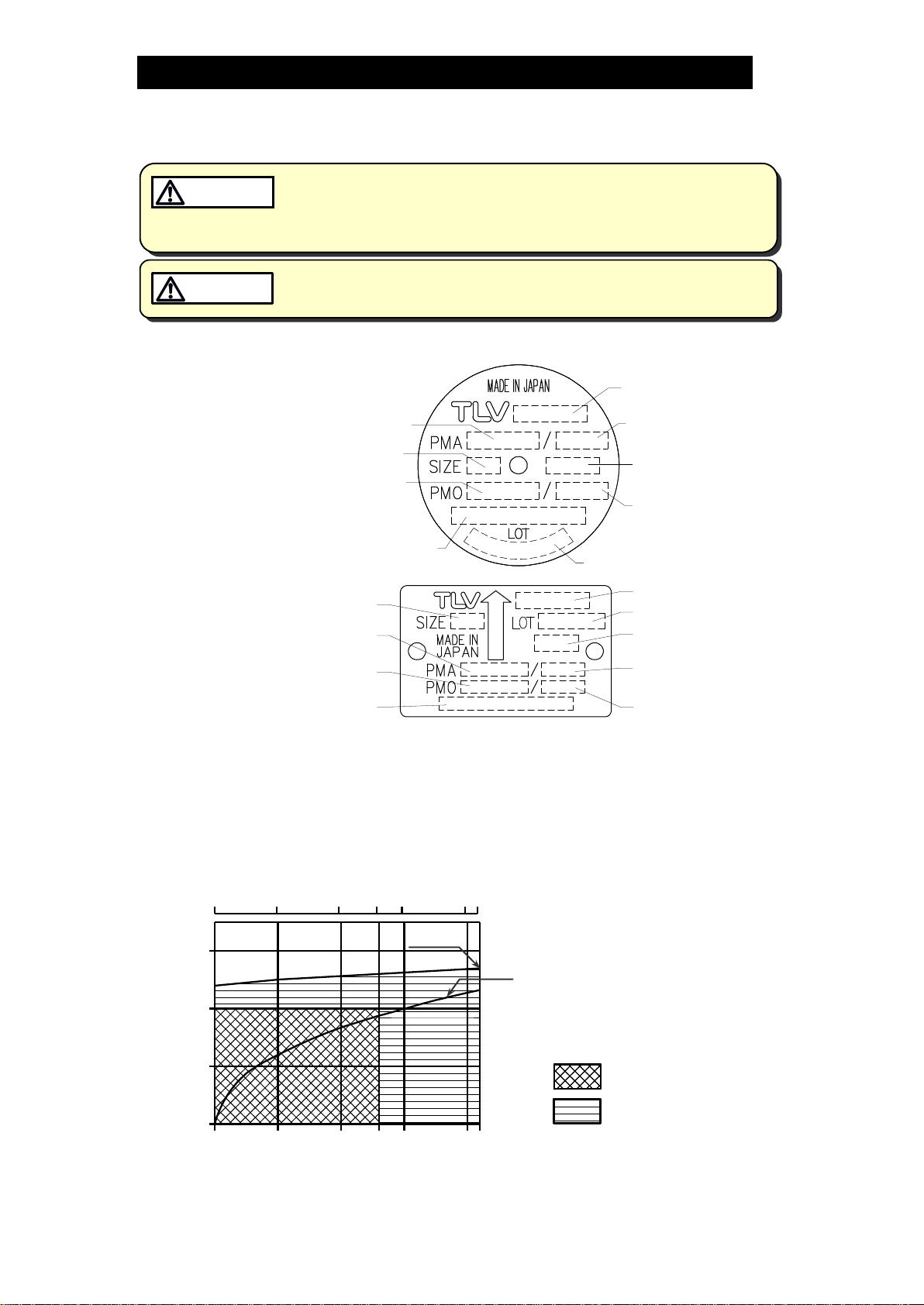
Refer to the product nameplate for detailed specifications.
LA13L
Production Lot No.
Valve No.**
Model
Maximum Allowable
Temperature (TMA)*
Nominal Diameter***
Maximum Operating
Temperature (TMO)
Maximum Allowable
Pressure*
Maximum Operating
Pressure
X-element Type
LA13/LA21
Model
Production Lot No.
X-element Type
Maximum Allowable
Temperature (TMA)*
Maximum Operating
Temperature (TMO)
Nominal Diameter
Maximum Allowable
Pressure*
Maximum Operating
Pressure
Valve No.**
*Maximum allowable pressure (PMA) and maximum allowable temperature (TMA) are PRESSURE
SHELL DESIGN CONDITIONS, NOT OPERATING CONDITIONS.
**Valve No. is displayed for products with options. This item is omitted from the nameplate when there
are no options.
Maximum Operating Temperature
235 C
: LA13/LA13L
: LA21
0510 13 15 20 21
250
220
200
150
100 00.5 1.0 1.3 1.5 2.0 2.1
Operating Pressure (kg/cm2G)
Operating Pressure (MPaG)
Temperature (
C)
Saturated Steam Curve
Operating Temperature Range
172-65133M-04 (LA Series) 1 Oct 2021
5
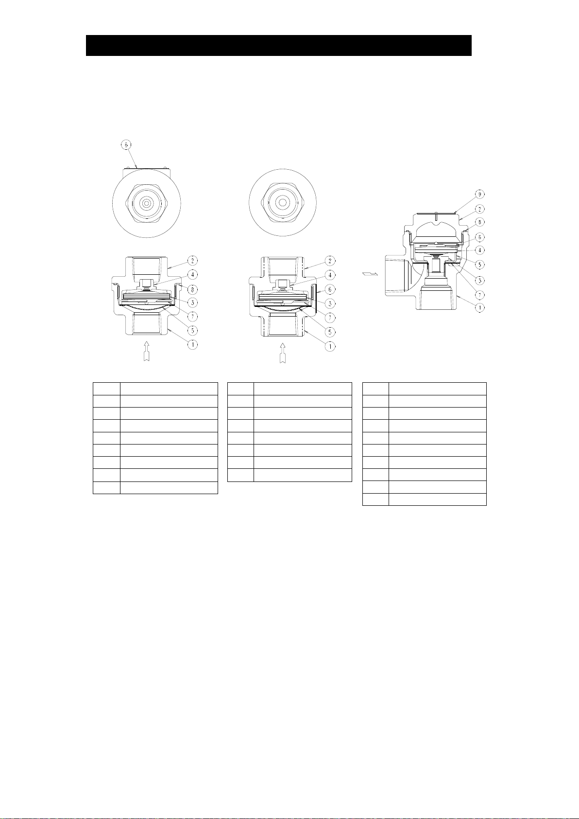
Configuration
LA13
LA21
LA13L
NO.
NAME
1
Body
2
Cover
3
X-element
4
Valve Seat
5
Screen
6
Nameplate
7
Spring Clip
8
Cover Gasket
NO.
NAME
1
Body
2
Cover
3
X-element
4
Valve Seat
5
Screen
6
Nameplate
7
Spring Clip
NO.
NAME
1
Body
2
Cover
3
Valve Seat
4
X-element
5
X-element Guide
6
Spring Clip
7
Screen
8
Cover Gasket
9
Nameplate

172-65133M-04 (LA Series) 1 Oct 2021
6
Installation
Install properly and DO NOT use this product outside the recommended
operating pressure, temperature and other specification ranges.
Improper use may result in such hazards as damage to the product or
malfunctions which may lead to serious accidents. Local regulations
may restrict the use of this product to below the conditions quoted.
CAUTION
Take measures to prevent people from coming into direct contact with
product outlets. Failure to do so may result in burns or other injury from
the discharge of fluids.
CAUTION
Installation, inspection, maintenance, repairs, disassembly, adjustment and valve
opening/closing should be carried out only by trained maintenance personnel.
1. Before installation, be sure to remove all protective seals from the product.
2. Before installing the air vent, blow out the inlet piping to remove any piping
scraps, dirt and oil. Close the inlet valve after blowdown.
3. When using the air vent to remove air from steam equipment, install at a point
where air tends to collect (essentially, a place away from the steam inlet). To
increase the effectiveness of air removal, also install an air vent in front of the
steam equipment (at the primary side).
4. Install the air vent vertically, making sure the arrow on the air vent is pointing in
the direction of flow.
5. Be sure to connect the pipe to the discharge side at the outlet. If air, etc. is
discharged from the outlet, connect a pipe leading to a drain, etc. so the
discharge does not affect operations. Do not submerge the outlet pipe in water;
this may result in air vent failure if the pipe sucks up water containing rust and
scale.
6. Open the inlet valve and check to make sure that the air vent functions properly.
If there is a problem, determine the cause using the “Troubleshooting” section in this
manual.
Sample Installation
Equipment Equipment
LA13/LA21 LA13/LA21
Drainage Pit Drainage Pit
L
A
1
3
L
L
A
1
3
,

172-65133M-04 (LA Series) 1 Oct 2021
7
Maintenance
Take measures to prevent people from coming into direct contact with
product outlets. Failure to do so may result in burns or other injury from
the discharge of fluids.
CAUTION
Be sure to use only the recommended components when repairing the
product, and NEVER attempt to modify the product in any way. Failure to
observe these precautions may result in damage to the product or burns
or other injury due to malfunction or the discharge of fluids.
CAUTION
Operational Check
A visual inspection according to the following items should be done on a daily basis
to determine whether the air vent is operating properly or has failed. Periodically (at
least biannually) the operation should also be checked by using a stethoscope,
thermometer or TLV Pocket TrapMan.
If the air vent should fail, it may cause damage to piping and equipment, resulting in
faulty or low quality products or losses due to steam leakage.
Normal
:
The sound of flow can be heard while air is discharged. When
air discharge finishes, the valve closes along with slight
discharge of steam.
Blocked
(Discharge
Impossible)
:
No air is discharged. The air vent is quiet and makes no noise,
and its surface temperature is low.
Blowing
:
Live steam continuously blows from the outlet and there is a
continuous metallic sound.
Steam Leakage
:
Live steam is leaking through the outlet, accompanied by a
high-pitched sound.
Parts Inspection
When parts have been removed, or during periodic inspections, use the following
table to inspect the parts and replace any that are found to be defective.
Procedure
Gasket: Check for warping or damage
Screen: Check for clogging or corrosion damage
X-element: Check for damage
Valve seat: Check for damage
Check inside of body for rust and scale
Check X-element valve and valve seat for rust and scale or oil film,
and also check for wear
172-65133M-04 (LA Series) 1 Oct 2021
8
Disassembly/Reassembly
When disassembling or removing the product, wait until the internal
pressure equals atmospheric pressure and the surface of the product
has cooled to room temperature. Disassembling or removing the
product when it is hot or under pressure may lead to discharge of fluids,
causing burns, other injuries or damage.
CAUTION
Use the following procedures to remove components. Use the same procedures in
reverse to reassemble. Installation, inspection, maintenance, repairs, disassembly,
adjustment and valve opening/closing should be carried out only by trained
maintenance personnel.
Removing/Reattaching Body (LA13/LA21)
Part
During Disassembly
During Reassembly
Body
Remove with a socket wrench
Consult the table of tightening torques and
tighten to the proper torque
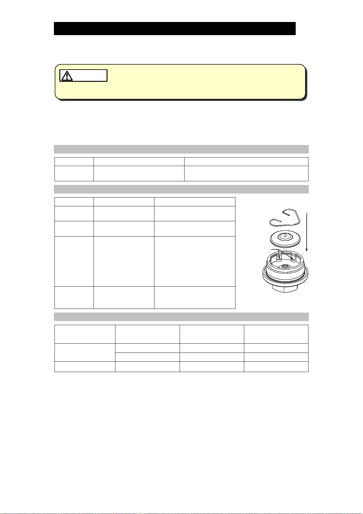
Removing/Reassembling Parts Inside Cover (LA13/LA21)
Part
During Disassembly
During Reassembly
Figure A
Spring Clip
Slot
Screen
Remove without
bending
Being careful not to bend it,
insert with the right side up
Spring Clip
Remove with needle-
nose pliers
Fit securely into the spring
clip slots
X-element
Grasp the ball on the
top of the X-element
with pliers and
remove
Make sure the side of the
X-element with the ball on it
is facing up and insert,
keeping the X-element level
and making sure it does not
catch on the cover (see
Figure A)
Cover
Gasket
(LA13 only)
Remove the gasket
and clean sealing
surfaces
Replace the gasket only if
warped or damaged
Table of Tightening Torques (LA13, LA21)
Part
Size
mm
Torque
N∙m
Distance Across Flats
mm
Body/Cover (LA13)
15
80
27
20, 25
80
41
Body/Cover (LA21)
10, 15
120
27
(1 Nm 10 kgcm)
NOTE:-LA13: DO NOT coat threaded portions with anti-seize
-LA21: Coat all threaded portions with anti-seize
-If drawings or other special documentation were supplied for the product, any torque
given there takes precedence over values shown here.
172-65133M-04 (LA Series) 1 Oct 2021
9
Removing/Reattaching Cover (LA13L)
Part
During Disassembly
During Reassembly
Cover
Remove with a socket wrench
Consult the table of tightening torques and
tighten to the proper torque
Cover
Gasket
Remove the gasket and clean
sealing surfaces
Replace the gasket only if warped or
damaged
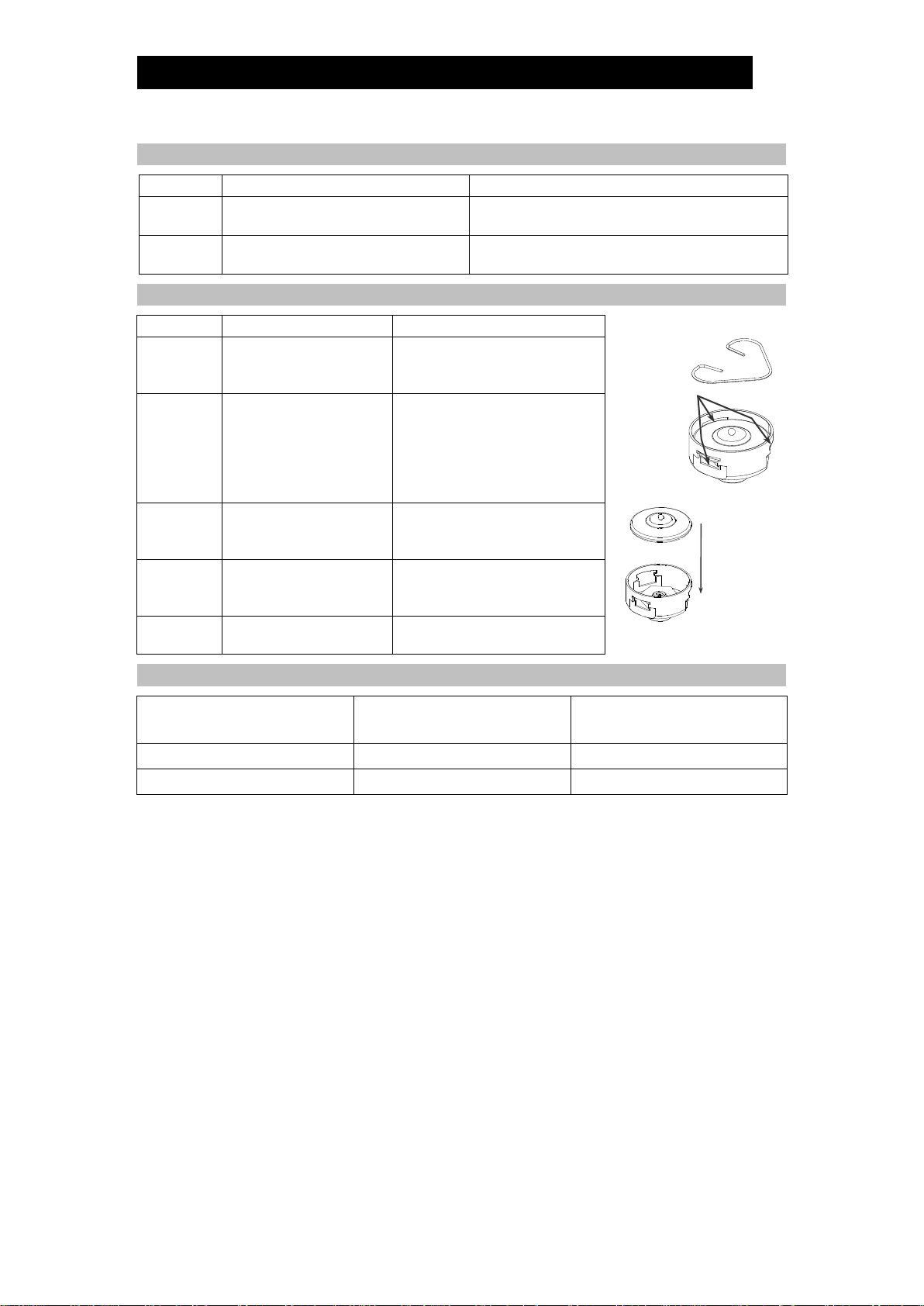
Removing/Reassembling Parts Inside Body (LA13L)
Part
During Disassembly
During Reassembly
Figure B
Spring Clip
Slot
Figure C
Spring Clip
Use needle-nose pliers
to remove, or remove
by hand
Insert securely into the slots in
the X-element guide (see
Figure B)
X-element
Grasp the ball on the
top of the X-element
with pliers and remove
Make sure the side of the
X-element with the ball on it is
facing up and insert, keeping
the X-element level and
making sure it does not catch
on the guide (see Figure C)
Valve Seat
Remove with a socket
wrench
Consult the table of tightening
torques and tighten to proper
torque
X-element
Guide
Remove without
bending
Fix with the valve seat and
make sure the X-element can
be inserted smoothly
Screen
Remove without
bending
Reinsert without bending
Table of Tightening Torques (LA13L)
Part
Torque
N∙m
Distance Across Flats
mm
Cover
80
32
Valve Seat
35
19
(1 Nm 10 kgcm)
NOTE: -LA13L: DO NOT coat threaded portions with anti-seize.
-If drawings or other special documentation were supplied for the product, any torque
given there takes precedence over values shown here.

172-65133M-04 (LA Series) 1 Oct 2021
10
Exploded View
LA13
LA21
LA13L
Body Body Cover
Screen Screen Cover Gasket
Spring Clip
X-element X-element X-element
Spring Clip Spring Clip
Cover
Gasket Cover Valve Seat
X-element
Guide
Screen
Body
Nameplate
Nameplate
Cover

172-65133M-04 (LA Series) 1 Oct 2021
11
Troubleshooting
When disassembling or removing the product, wait until the internal
pressure equals atmospheric pressure and the surface of the product
has cooled to room temperature. Disassembling or removing the
product when it is hot or under pressure may lead to discharge of fluids,
causing burns, other injuries or damage.
CAUTION
When the product fails to operate properly, use the following table to locate and
remedy the cause.
Problem
Cause
Remedy
No air is discharged
(blocked) or discharge
is poor
The X-element is stuck to the
valve seat
Clean parts
The valve seat is blocked
Clean the valve seat, or replace
with a new valve seat (LA13L) or
cover
The screen is clogged
Clean parts
The air vent operating pressure
exceeds the maximum specified
pressure, or there is insufficient
pressure differential between the
air vent inlet and outlet
Compare specifications and
actual operating conditions
Steam is discharged or
leaks from the outlet
(blowing)
(steam leakage)
There is rust or scale between the
X-element valve and valve seat
Clean parts
The X-element valve and valve
seat are damaged
Replace with a new X-element
and/or cover (LA13L: also the
valve seat)
The X-element is broken
Replace with a new X-element
Improper installation
Correct the installation
Air vent vibration
Lengthen the inlet piping and
fasten it securely
Steam is leaking from
a place other than the
outlet
Gasket deterioration or damage
Replace with a new gasket
Improper tightening torques were
used
Tighten to the proper torque

172-65133M-04 (LA Series) 1 Oct 2021
12
TLV EXPRESS LIMITED WARRANTY
Subject to the limitations set forth below, TLV CO., LTD., a Japanese corporation
(“TLV”), warrants that products which are sold byit, TLV International Inc. (“TII”) or one of
its group companies excluding TLV Corporation (a corporation of the United States of
America), (hereinafter the “Products”) are designed and manufactured by TLV, conform
to the specifications published by TLV for the corresponding part numbers (the
“Specifications”) and are free from defective workmanship and materials. The party
from whom the Products were purchased shall be known hereinafter as the “Seller”. With
regard to products or components manufactured byunrelated third parties (the
“Components”), TLV provides no warranty other than the warranty from the third party
manufacturer(s), if any.
Exceptions to Warranty
This warranty does not cover defects or failures caused by:
1. improper shipping, installation, use, handling, etc., by persons other than TLV,
TII or TLV group company personnel, or service representatives authorized by
TLV; or
2. dirt, scale or rust, etc.; or
3. improper disassembly and reassembly, or inadequate inspection and
maintenance by persons other than TLV or TLV group company personnel, or
service representatives authorized by TLV; or
4. disasters or forces of nature or Acts of God; or
5. abuse, abnormal use, accidents or any other cause beyond the control of TLV,
TII or TLV group companies; or
6. improper storage, maintenance or repair; or
7. operation of the Products not in accordance with instructions issued with the
Products or with accepted industry practices; or
8. use for a purpose or in a manner for which the Products were not intended; or
9. use of the Products in a manner inconsistent with the Specifications; or
10. use of the Products with Hazardous Fluids (fluids other than steam, air, water,
nitrogen, carbon dioxide and inert gases (helium, neon, argon, krypton, xenon
and radon)); or
11. failure to follow the instructions contained in the TLV Instruction Manual for the
Product.
Duration of Warranty
This warranty is effective for a period of one (1) year after delivery of Products to the
first end user. Notwithstanding the foregoing, asserting a claim under this warranty
must be brought within three (3) years after the date of delivery to the initial buyer if
not sold initially to the first end user.
ANY IMPLIED WARRANTIES NOT NEGATED HEREBY WHICH MAY ARISE BY
OPERATION OF LAW, INCLUDING THE IMPLIED WARRANTIES OF MERCHANTABILITY
AND FITNESS FOR A PARTICULAR PURPOSE AND ANY EXPRESS WARRANTIES NOT
NEGATED HEREBY, ARE GIVEN SOLELY TO THE INITIAL BUYER AND ARE LIMITED IN
DURATION TO ONE (1) YEAR FROM THE DATE OF SHIPMENT BY THE SELLER.
Exclusive Remedy
THE EXCLUSIVE REMEDY UNDER THIS WARRANTY, UNDER ANY EXPRESS WARRANTY
OR UNDER ANY IMPLIED WARRANTIES NOT NEGATED HEREBY (INCLUDING THE
IMPLIED WARRANTIES OF MERCHANTABILITY AND FITNESS FOR A PARTICULAR
PURPOSE), IS REPLACEMENT; PROVIDED: (a) THE CLAIMED DEFECT IS REPORTED TO
THE SELLER IN WRITING WITHIN THE WARRANTY PERIOD, INCLUDING A DETAILED

172-65133M-04 (LA Series) 1 Oct 2021
13
WRITTEN DESCRIPTION OF THE CLAIMED DEFECT AND HOW AND WHEN THE
CLAIMED DEFECTIVE PRODUCT WAS USED; AND (b) THE CLAIMED DEFECTIVE
PRODUCT AND A COPY OF THE PURCHASE INVOICE IS RETURNED TO THE SELLER,
FREIGHT AND TRANSPORTATION COSTS PREPAID, UNDER A RETURN MATERIAL
AUTHORIZATION AND TRACKING NUMBER ISSUED BY THE SELLER. ALL LABOR
COSTS, SHIPPING COSTS, AND TRANSPORTATION COSTS ASSOCIATED WITH THE
RETURN OR REPLACEMENT OF THE CLAIMED DEFECTIVE PRODUCT ARE SOLELY THE
RESPONSIBILITY OF BUYER OR THE FIRST END USER. THE SELLER RESERVES THE
RIGHT TO INSPECT ON THE FIRST END USER’S SITE ANY PRODUCTS CLAIMED TO BE
DEFECTIVE BEFORE ISSUING A RETURN MATERIAL AUTHORIZATION. SHOULD SUCH
INSPECTION REVEAL, IN THE SELLER’S REASONABLE DISCRETION, THAT THE
CLAIMED DEFECT IS NOT COVERED BY THIS WARRANTY, THE PARTY ASSERTING THIS
WARRANTY SHALL PAY THE SELLER FOR THE TIME AND EXPENSES RELATED TO
SUCH ON-SITE INSPECTION.
Exclusion of Consequential and Incidental Damages
IT IS SPECIFICALLY ACKNOWLEDGED THAT THIS WARRANTY, ANY OTHER EXPRESS
WARRANTY NOT NEGATED HEREBY, AND ANY IMPLIED WARRANTY NOT NEGATED
HEREBY, INCLUDING THE IMPLIED WARRANTIES OF MERCHANTABILITY AND FITNESS
FOR A PARTICULAR PURPOSE, DO NOT COVER, AND NEITHER TLV, TII NOR ITS TLV
GROUP COMPANIES WILL IN ANY EVENT BE LIABLE FOR, INCIDENTAL OR
CONSEQUENTIAL DAMAGES, INCLUDING, BUT NOT LIMITED TO LOST PROFITS, THE
COST OF DISASSEMBLY AND SHIPMENT OF THE DEFECTIVE PRODUCT, INJURY TO
OTHER PROPERTY, DAMAGE TO BUYER’S OR THE FIRST END USER’S PRODUCT,
DAMAGE TO BUYER’S OR THE FIRST END USER’S PROCESSES, LOSS OF USE, OR
OTHER COMMERCIAL LOSSES. WHERE, DUE TO OPERATION OF LAW,
CONSEQUENTIAL AND INCIDENTAL DAMAGES UNDER THIS WARRANTY, UNDER ANY
OTHER EXPRESS WARRANTY NOT NEGATED HEREBY OR UNDER ANY IMPLIED
WARRANTY NOT NEGATED HEREBY (INCLUDING THE IMPLIED WARRANTIES OF
MERCHANTABILITY AND FITNESS FOR A PARTICULAR PURPOSE) CANNOT BE
EXCLUDED, SUCH DAMAGES ARE EXPRESSLY LIMITED IN AMOUNT TO THE PURCHASE
PRICE OF THE DEFECTIVE PRODUCT. THIS EXCLUSION OF CONSEQUENTIAL AND
INCIDENTAL DAMAGES, AND THE PROVISION OF THIS WARRANTY LIMITING REMEDIES
HEREUNDER TO REPLACEMENT, ARE INDEPENDENT PROVISIONS, AND ANY
DETERMINATION THAT THE LIMITATION OF REMEDIES FAILS OF ITS ESSENTIAL
PURPOSE OR ANY OTHER DETERMINATION THAT EITHER OF THE ABOVE REMEDIES IS
UNENFORCEABLE, SHALL NOT BE CONSTRUED TO MAKE THE OTHER PROVISIONS
UNENFORCEABLE.
Exclusion of Other Warranties
THIS WARRANTY IS IN LIEU OF ALL OTHER WARRANTIES, EXPRESS OR IMPLIED,
AND ALL OTHER WARRANTIES, INCLUDING BUT NOT LIMITED TO THE IMPLIED
WARRANTIES OF MERCHANTABILITY AND FITNESS FOR A PARTICULAR PURPOSE,
ARE EXPRESSLY DISCLAIMED.
Severability
Any provision of this warranty which is invalid, prohibited or unenforceable in any
jurisdiction shall, as to such jurisdiction, be ineffective to the extent of such invalidity,
prohibition or unenforceability without invalidating the remaining provisions hereof,
and any such invalidity, prohibition or unenforceability in any such jurisdiction shall
not invalidate or render unenforceable such provision in any other jurisdiction.

172-65133M-04 (LA Series) 1 Oct 2021
14
Service
For Service or Technical Assistance: Contact your TLV representative or your regional TLV
office.
In Europe:
Daimler-Benz-Straße 16-18, 74915 Waibstadt, Germany
Tel:
Fax:
[49]-(0)7263-9150-0
[49]-(0)7263-9150-50
Units 7 & 8, Furlong Business Park, Bishops Cleeve, Gloucestershire GL52
8TW, U.K.
Tel:
Fax:
[44]-(0)1242-227223
[44]-(0)1242-223077
Parc d’Ariane 2, bât. C, 290 rue Ferdinand Perrier, 69800 Saint Priest,
France
Tel:
Fax:
[33]–(0)4-72482222
[33]-(0)4-72482220
In North America:
13901 South Lakes Drive, Charlotte, NC 28273-6790, U.S.A.
Tel:
Fax:
[1]-704-597-9070
[1]-704-583-1610
In Mexico and Latin America:
Av. Jesús del Monte 39-B-1001, Col. Hda. de las Palmas, Huixquilucan,
Edo. de México, 52763, Mexico
Tel:
Fax:
[52]-55-5359-7949
[52]-55-5359-7585
In Oceania:
Unit 8, 137-145 Rooks Road, Nunawading, Victoria 3131, Australia
Tel:
Fax:
[61]-(0)3-9873 5610
[61]-(0)3-9873 5010
In East Asia:
36 Kaki Bukit Place, #02-01/02, Singapore 416214
Tel:
Fax:
[65]-6747 4600
[65]-6742 0345
Room 5406, No. 103 Cao Bao Road, Shanghai, China 200233
Tel:
Fax:
[86]-(0)21-6482-8622
[86]-(0)21-6482-8623
No.16, Jalan MJ14, Taman Industri Meranti Jaya, 47120 Puchong,
Selangor, Malaysia
Tel:
Fax:
[60]-3-8065-2928
[60]-3-8065-2923
252/94 (K-L) 17th Floor, Muang Thai-Phatra Complex Tower B,
Rachadaphisek Road, Huaykwang, Bangkok 10310, Thailand
Tel:
Fax:
[66]-2-693-3799
[66]-2-693-3979
#302-1 Bundang Technopark B, 723 Pangyo-ro, Bundang, Seongnam,
Gyeonggi, 13511, Korea
Tel:
Fax:
[82]-(0)31-726-2105
[82]-(0)31-726-2195
In the Middle East:
Building2W,No.M002, PO Box371684,DubaiAirportFreeZone,Dubai, UAE
Email:
sales-m[email protected]
In Other Countries:
881 Nagasuna, Noguchi, Kakogawa, Hyogo 675-8511, Japan
Tel:
Fax:
[81]-(0)79-427-1818
[81]-(0)79-425-1167
Manufacturer:
881 Nagasuna, Noguchi, Kakogawa, Hyogo 675-8511, Japan
Tel:
Fax:
[81]-(0)79-422-1122
[81]-(0)79-422-0112
This manual suits for next models
2
Table of contents
Other TLV Fan manuals


Popular Fan manuals by other brands

Termozeta
Termozeta AIRZETA LIVING PLUS instruction manual

Hinkley
Hinkley IVER 56 instruction manual

Monte Carlo Fan Company
Monte Carlo Fan Company Ceiling Fans owner's manual

Becker
Becker SV 5.250 operating instructions

Vortice
Vortice VORT HRW 30 MONO EVO WiFi Instruction booklet

Hardware House
Hardware House 162272 Owner's instruction manual


