TLV VS1C User manual

172-65392MA-08 (VS1C) 25 November 2021
Automatic Air Vent
VS1C
Copyright © 2021 by TLV CO., LTD.
All rights reserved

172-65392MA-08 (VS1C) 25 Nov 2021
1
Contents
Introduction .......................................................................1
Safety Considerations.......................................................2
Features............................................................................4
Operation ..........................................................................4
Specifications....................................................................5
Configuration.....................................................................6
Installation.........................................................................7
Maintenance......................................................................8
Disassembly/Reassembly.................................................9
Troubleshooting ..............................................................11
TLV EXPRESS LIMITED WARRANTY...........................12
Service ............................................................................14
Introduction
Thank you for purchasing the TLV automatic air vent.
This product has been thoroughly inspected before being shipped from the factory.
When the product is delivered, before doing anything else, check the specifications
and external appearance to make sure nothing is out of the ordinary. Also be sure to
read this manual carefully before use and follow the instructions to be sure of using
the product properly.
The VS1C automatic air vent is designed to automatically discharge/release air
trapped in water-carrying pipes during water transport. It also automatically
discharges the air that was entrained in the water during operation and has
subsequently been separated and collected in specific locations in the piping.
If detailed instructions for special order specifications or options not contained in this
manual are required, please contact TLV for full details.
This instruction manual is intended for use with the model(s) listed on the front cover.
It is necessary not only for installation but for subsequent maintenance,
disassembly/reassembly and troubleshooting. Please keep it in a safe place for
future reference.
172-65392MA-08 (VS1C) 25 Nov 2021
2
Safety Considerations
Read this section carefully before use and be sure to follow the instructions.
Installation, inspection, maintenance, repairs, disassembly, adjustment and valve
opening/closing should be carried out only by trained maintenance personnel.
The precautions listed in this manual are designed to ensure safety and prevent
equipment damage and personal injury. For situations that may occur as a result of
erroneous handling, three different types of cautionary items are used to indicate
the degree of urgency and the scale of potential damage and danger: DANGER,
WARNING and CAUTION.
The three types of cautionary items above are very important for safety: be sure to
observe all of them as they relate to installation, use, maintenance, and repair.
Furthermore, TLV accepts no responsibility for any accidents or damage occurring
as a result of failure to observe these precautions.
Symbols
Indicates a DANGER, WARNING or CAUTION item.
Indicates an urgent situation which poses a threat of death or
serious injury
Indicates that there is a potential threat of death or serious injury
Indicates that there is a possibility of injury or equipment/product
damage
DO NOT use for toxic, flammable or otherwise hazardous
fluids.
This product is an air vent that discharges air from water piping
system. Use only for water and/or air. This product is for intended
use only. Improper use may result in such hazards as damage to
the product or malfunctions that may lead to serious accidents.
NEVER apply direct heat to the float.
The float may explode due to increased internal pressure, causing
accidents leading to serious injury or damage to property and
equipment.
Install properly and DO NOT use this product outside the
recommended operating pressure, temperature and other
specification ranges.
Improper use may result in such hazards as damage to the
product or malfunctions that may lead to serious accidents. Local
regulations may restrict the use of this product to below the
conditions quoted.
DO NOT use this product in excess of the maximum operating
pressure differential.
Such use could make discharge impossible (blocked).
Continued on the next page
DANGER
WARNING
CAUTION
WARNING
CAUTION

172-65392MA-08 (VS1C) 25 Nov 2021
3
Take measures to prevent people from coming into direct
contact with product outlets.
Failure to do so may result in burns or other injury from the
discharge of fluids.
When disassembling or removing the product, wait until the
internal pressure equals atmospheric pressure and the
surface of the product has cooled to room temperature.
Disassembling or removing the product when it is hot or under
pressure may lead to discharge of fluids, causing burns, other
injuries or damage.
Be sure to use only the recommended components when
repairing the product, and NEVER attempt to modify the
product in any way.
Failure to observe these precautions may result in damage to the
product and burns or other injury due to malfunction or the
discharge of fluids.
Use only under conditions in which no freeze-up will occur.
Freezing may damage the product, leading to fluid discharge,
which may cause burns or other injury.
Use only under conditions in which no water hammer will
occur.
The impact of water hammer may damage the product, leading to
fluid discharge, which may cause burns or other injury.
CAUTION
172-65392MA-08 (VS1C) 25 Nov 2021
4
Features
1. Precision-ground float and 3-point seating provide the tightest seal.
2. All stainless steel construction provides outstanding corrosion resistance.
3. The air vent has no hinges or levers: the only moving part is the precision-ground
float, which eliminates concentrated wear and provides long service life.
4. Simple construction with few parts allows for easy maintenance.
5. The air vent is small and light.
Operation
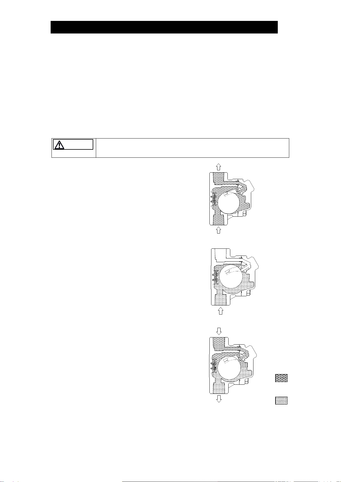
Take measures to prevent people from coming into direct contact with
product outlets.
Failure to do so may result in burns or other injury from the discharge of fluids.
1. When water is transported, air inside the
piping is forced into the air vent by the
pressure of the flow.
The float inside the air vent is in the lower
position, thus the valve is fully open and
allows the air that enters the air vent and
fills the area around the float to then be
discharged.
2. When discharge is completed, as water
flows into the air vent, the rising water level
causes the float to rise and to close the
valve.
If there is a rapid rise in water level (caused
by rapidly opening a shut-off valve, etc.), a
small amount of water may leak with
discharged air immediately before the air
vent closes.
3. If air enters the air vent while the water is
causing the valve to be closed, the air
causes the water level to drop, thus the
float loses buoyancy and the valve opens.
After the air is discharged, the water level
once again rises and the valve again
becomes closed. In this manner, the air
vent constantly responds to the amount of
water flow by automatically adjusting
discharge.
4. When draining the piping, the air vent
automatically opens to introduce air and
remove water more easily (preventing a
vacuum from forming in the piping).
CAUTION
Air
Water

172-65392MA-08 (VS1C) 25 Nov 2021
5
Specifications
DO NOT use for toxic, flammable or otherwise hazardous fluids.
This product is an air vent that discharges air from water piping system. Use only
for water and/or air. This product is for intended use only. Improper use may
result in such hazards as damage to the product or malfunctions that may lead to
serious accidents.
Install properly and DO NOT use this product outside the recommended
operating pressure, temperature and other specification ranges.
Improper use may result in such hazards as damage to the product or
malfunctions which may lead to serious accidents. Local regulations may restrict
the use of this product to below the conditions quoted.
DO NOT use this product in excess of the maximum operating pressure
differential.
Such use could make discharge impossible (blocked).
Use only under conditions in which no freeze-up will occur.
Freezing may damage the product, leading to fluid discharge, which may cause
burns or other injury.
Refer to the product nameplate for detailed specifications.
A
Model
B
Nominal Diameter
C
Maximum Allowable Pressure (PMA)
D
Maximum Allowable Temperature (TMA)
E
Maximum Differential Pressure (PMX)
F
Maximum Operating Temperature (TMO)
G
Production Lot No.
H
Valve No.**
* Maximum allowable pressure (PMA) and maximum allowable temperature (TMA) are PRESSURE
SHELL DESIGN CONDITIONS, NOT OPERATING CONDITIONS.
** Valve No. is displayed for products with options. This item is omitted from the nameplate when there
are no options.
WARNING
CAUTION
172-65392MA-08 (VS1C) 25 Nov 2021
6
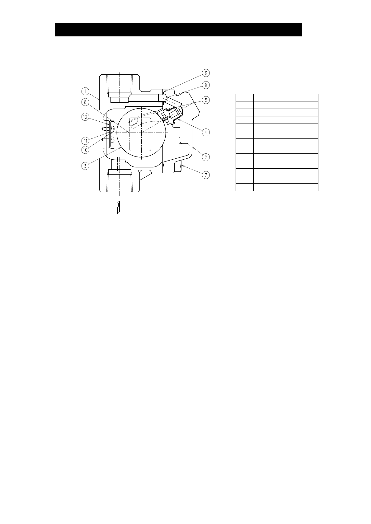
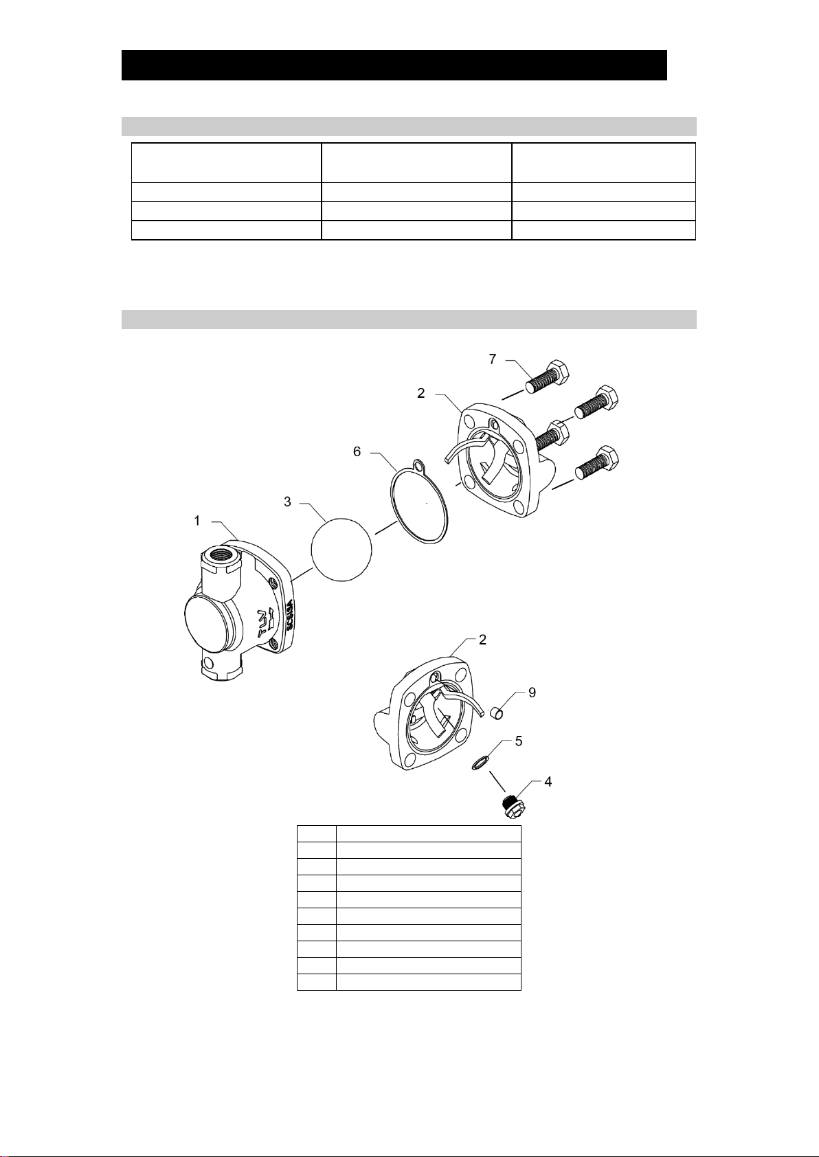
Configuration
No.
Name
1
Body
2
Cover
3
Float
4
Valve Seat
5
Valve Seat Gasket
6
Cover Gasket
7
Cover Bolt
8
Nameplate
9
Connector
10
Screw
11
Spring Washer
12
Guide Plate

172-65392MA-08 (VS1C) 25 Nov 2021
7
Installation
DO NOT use for toxic, flammable or otherwise hazardous fluids.
This product is an air vent that discharges air from water piping system. Use only
for water and/or air. This product is for intended use only. Improper use may
result in such hazards as damage to the product or malfunctions that may lead to
serious accidents.
Install properly and DO NOT use this product outside the recommended
operating pressure, temperature and other specification ranges.
Improper use may result in such hazards as damage to the product or
malfunctions which may lead to serious accidents. Local regulations may restrict
the use of this product to below the conditions quoted.
Take measures to prevent people from coming into direct contact with
product outlets.
Failure to do so may result in burns or other injury from the discharge of fluids.
Installation, inspection, maintenance, repairs, disassembly, adjustment and valve
opening/closing should be carried out only by trained maintenance personnel.
1. Before installation, be sure to remove all protective seals.
2. Before installing the product, open the inlet valve and blow out the piping to
remove any piping scraps, dirt and oil. Close the inlet valve after blowdown.
3. This product must be installed vertically, with the inlet at the bottom and the outlet at
thetop, andshouldbeinclined no morethan5° horizontallyandfront-to-back (Figure 2).
4. Install the product in a location where air is likely to collect, such as a bend in the
piping.
5. Install outlet piping leading to a drainage vessel or ditch. Make sure the end of the
pipe is above the waterline, so that dirt and water can not be sucked up by vacuum
when the system shuts down (Figure 1).
6. Inlet piping with no horizontal portion is recommended for water/air displacement.
If there is a horizontal portion, make the pipe diameter of the horizontal portion
larger than the vertical portion or make the horizontal portion as short as possible.
7. Make sure the inlet piping diameter is at least as large as the product’s inlet
diameter. For the inlet connection especially for the products with a nominal
diameter of 15 mm (1/2in), use a pipe/fitting, etc. with an inner diameter of at least
16 mm (5/8in), such as a schedule 40 pipe nipple with a nominal diameter of 15
mm (1/2in). A smaller pipe may prevent water/air displacement.
8. Installation of an isolation valve just before the product’s main connection is
recommended as it enables maintenance during operation. A full-bore ball valve
is recommended.
9. Make sure to take measures to prevent foreign matter fromflowing into the product.
If there is a problem, determine the cause using the “Troubleshooting” section in this
manual.
Figure 1
Figure 2
Tolerance Angle for
Installation: 5°
WARNING
CAUTION
Make sure the end
of the pipe is above
the waterline.
172-65392MA-08 (VS1C) 25 Nov 2021
8
Maintenance
Take measures to prevent people from coming into direct contact with
product outlets.
Failure to do so may result in burns or other injury from the discharge of fluids.
Be sure to use only the recommended components when repairing the
product, and NEVER attempt to modify the product in any way.
Failure to observe these precautions may result in damage to the product or
burns or other injury due to malfunction or the discharge of fluids.
Operational Check
A visual inspection of the following items should be done on a daily basis to
determine whether the product is operating properly or has failed.
If the product should fail, it may cause water leakage or hindrance to water flow.
Normal:
Air is discharged as it accumulates, with the air vent closing
(with no leakage) when no air is present in the piping.
Blocked:
(Discharge Impossible)
No air is discharged though air accumulates in the product.
Leakage:
Water from the piping is discharged or leaks through the
product.
Parts Inspection
When parts have been removed, or during periodic inspections, use the following
table to inspect the parts and replace any that are found to be defective.
Procedure
Gaskets: Check for warping or scratches
Valve Seat Surface: Check for scratches or wear
Float: Check for scratches or dents, or water inside
Guide Plate: Check for damage
CAUTION

172-65392MA-08 (VS1C) 25 Nov 2021
9
Disassembly/Reassembly
NEVER apply direct heat to the float.
The float may explode due to increased internal pressure, causing accidents
leading to serious injury or damage to property and equipment.
When disassembling or removing the product, wait until the internal
pressure equals atmospheric pressure and the surface of the product has
cooled to room temperature.
Disassembling or removing the product when it is hot or under pressure may lead
to discharge of fluids, causing burns, other injuries or damage.
Be sure to use only the recommended components when repairing the
product, and NEVER attempt to modify the product in any way.
Failure to observe these precautions may result in damage to the product or
burns or other injury due to malfunction or the discharge of fluids.
Use the following procedures to remove components. Use the same procedures in
reverse to reassemble.
(Installation, inspection, maintenance, repairs, disassembly, adjustment and valve
opening/closing should be carried out only by trained maintenance personnel.)
Detaching/Reattaching the Cover and its Components
Part
During Disassembly
During Reassembly
Cover Bolt 7
Remove with a socket wrench
Consult the table of tightening torques
and tighten to the proper torque
Cover 2
Remove carefully; take care to prevent
any damage to the float, which may
fall out when the cover is removed
Make sure the sealing surfaces are
clean, then reattach; be careful not to
bend the float guides
Float 3
Remove, being careful not to scratch
the polished surface
Insert, being careful not to scratch the
polished surface
Connector 9
Remove the connector
Reinsert into the hole in the cover
Cover Gasket
6
Remove if damaged
Replace with a new gasket if warped
or damaged
Valve Seat 4
Remove with a socket wrench
Replace with a new valve seat if
misshapen or damaged
Consult the table of tightening torques
and tighten to the proper torque
Valve Seat
Gasket 5
Remove the gasket and clean sealing
surfaces
Replace with a new gasket if warped
or damaged
* Float Guides
NOTE: The float guides are correctly positioned when shipped
from the factory, so be careful when handling them. Tight
sealing cannot be guaranteed if the float guides have
been moved out of position.
Body Interior Plate (part No. 12)
The guide plate built into the body with screws (and spring washer) does not require
removal during normal product disassembly. The plate should only be replaced when it
has become deformed or damaged. Upon reassembly, tighten to the proper torque.
WARNING
CAUTION
172-65392MA-08 (VS1C) 25 Nov 2021
10
Table of Tightening Torques
Part Name
Torque
Distance Across Flats
Nm
(lbfft)
mm
(in)
Cover Bolt 7
45
(33)
17
(21/32)
Valve Seat 4
15
(11)
13
(1/2)
Screw (for Guide Plate 12)
0.3
(0.22)
+
NOTE: - Coat all threaded portions with anti-seize. (1 Nm 10 kgcm)
-If drawings or other special documentation were supplied for the product,
any torque given there takes precedence over values shown here.
Exploded View
No.
Name
1
Body
2
Cover
3
Float
4
Valve Seat
5
Valve Seat Gasket
6
Cover Gasket
7
Cover Bolt
8
Nameplate (not shown)
9
Connector

172-65392MA-08 (VS1C) 25 Nov 2021
11
Troubleshooting
NEVER apply direct heat to the float.
The float may explode due to increased internal pressure, causing accidents
leading to serious injury or damage to property and equipment.
When disassembling or removing the product, wait until the internal
pressure equals atmospheric pressure and the surface of the product has
cooled to room temperature.
Disassembling or removing the product when it is hot or under pressure may lead
to discharge of fluids, causing burns, other injuries or damage.
When the product fails to operate properly, use the following table to locate the cause
and remedy.
Problem
Cause
Remedy
No air discharged
(blocked) or
discharge is poor
Air is not reaching the vent because the
water in the piping is not being displaced
by air
Correct the inlet piping
(Inner diameter should be at
least 16mm (5/8in))
The valve seat is clogged
Clean the valve seat
The inlet or outlet piping is clogged
Clean the piping and any
upstream strainer
Operating pressure exceeds the rated
maximum operating pressure
Replace with a product of
suitable operating pressure
Water leaks when
valve is closed
The valve seat is clogged with dirt or scale
or is damaged
Clean or replace with a new
valve seat
The float is dirty or coated with a film, or
is deformed
Clean or replace with a new
float
Improper installation orientation
Correct the installation
Valve does not
close, and water
spurts out
Water is inside the float
Replace with a new float
The guide plate is damaged
Replace with a new plate
Specific gravity of the liquid is not suitable
for this product
Select a product with
suitable specifications for the
operating conditions
WARNING
CAUTION

172-65392MA-08 (VS1C) 25 Nov 2021
12
TLV EXPRESS LIMITED WARRANTY
Subject to the limitations set forth below, TLV CO., LTD., a Japanese corporation
(“TLV”), warrants that products which are sold by it, TLV International Inc. (“TII”) or
one of its group companies excluding TLV Corporation (a corporation of the United
States of America), (hereinafter the “Products”) are designed and manufactured by
TLV, conform to the specifications published by TLV for the corresponding part
numbers (the “Specifications”) and are free from defective workmanship and
materials. The party from whom the Products were purchased shall be known
hereinafter as the “Seller”. With regard to products or components manufactured by
unrelated third parties (the “Components”), TLV provides no warranty other than the
warranty from the third party manufacturer(s), if any.
Exceptions to Warranty
This warranty does not cover defects or failures caused by:
1. improper shipping, installation, use, handling, etc., by persons other than TLV,
TII or TLV group company personnel, or service representatives authorized by
TLV; or
2. dirt, scale or rust, etc.; or
3. improper disassembly and reassembly, or inadequate inspection and
maintenance by persons other than TLV or TLV group company personnel, or
service representatives authorized by TLV; or
4. disasters or forces of nature or Acts of God; or
5. abuse, abnormal use, accidents or any other cause beyond the control of TLV,
TII or TLV group companies; or
6. improper storage, maintenance or repair; or
7. operation of the Products not in accordance with instructions issued with the
Products or with accepted industry practices; or
8. use for a purpose or in a manner for which the Products were not intended; or
9. use of the Products in a manner inconsistent with the Specifications; or
10. use of the Products with Hazardous Fluids (fluids other than steam, air, water,
nitrogen, carbon dioxide and inert gases (helium, neon, argon, krypton, xenon
and radon)); or
11. failure to follow the instructions contained in the TLV Instruction Manual for the
Product.
Duration of Warranty
This warranty is effective for a period of one (1) year after delivery of Products to the
first end user. Notwithstanding the foregoing, asserting a claim under this warranty
must be brought within three (3) years after the date of delivery to the initial buyer if
not sold initially to the first end user.
ANY IMPLIED WARRANTIES NOT NEGATED HEREBY WHICH MAY ARISE BY
OPERATION OF LAW, INCLUDING THE IMPLIED WARRANTIES OF MERCHANTABILITY
AND FITNESS FOR A PARTICULAR PURPOSE AND ANY EXPRESS WARRANTIES NOT
NEGATED HEREBY, ARE GIVEN SOLELY TO THE INITIAL BUYER AND ARE LIMITED IN
DURATION TO ONE (1) YEAR FROM THE DATE OF SHIPMENT BY THE SELLER.
Exclusive Remedy
THE EXCLUSIVE REMEDY UNDER THIS WARRANTY, UNDER ANY EXPRESS
WARRANTY OR UNDER ANY IMPLIED WARRANTIES NOT NEGATED HEREBY
(INCLUDING THE IMPLIED WARRANTIES OF MERCHANTABILITY AND FITNESS FOR A
PARTICULAR PURPOSE), IS REPLACEMENT; PROVIDED: (a) THE CLAIMED DEFECT IS

172-65392MA-08 (VS1C) 25 Nov 2021
13
REPORTED TO THE SELLER IN WRITING WITHIN THE WARRANTY PERIOD, INCLUDING
A DETAILED WRITTEN DESCRIPTION OF THE CLAIMED DEFECT AND HOW AND WHEN
THE CLAIMED DEFECTIVE PRODUCT WAS USED; AND (b) THE CLAIMED DEFECTIVE
PRODUCT AND A COPY OF THE PURCHASE INVOICE IS RETURNED TO THE SELLER,
FREIGHT AND TRANSPORTATION COSTS PREPAID, UNDER A RETURN MATERIAL
AUTHORIZATION AND TRACKING NUMBER ISSUED BY THE SELLER. ALL LABOR
COSTS, SHIPPING COSTS, AND TRANSPORTATION COSTS ASSOCIATED WITH THE
RETURN OR REPLACEMENT OF THE CLAIMED DEFECTIVE PRODUCT ARE SOLELY
THE RESPONSIBILITY OF BUYER OR THE FIRST END USER. THE SELLER RESERVES
THE RIGHT TO INSPECT ON THE FIRST END USER’S SITE ANY PRODUCTS CLAIMED
TO BE DEFECTIVE BEFORE ISSUING A RETURN MATERIAL AUTHORIZATION. SHOULD
SUCH INSPECTION REVEAL, IN THE SELLER’S REASONABLE DISCRETION, THAT THE
CLAIMED DEFECT IS NOT COVERED BY THIS WARRANTY, THE PARTY ASSERTING
THIS WARRANTY SHALL PAY THE SELLER FOR THE TIME AND EXPENSES RELATED
TO SUCH ON-SITE INSPECTION.
Exclusion of Consequential and Incidental Damages
IT IS SPECIFICALLY ACKNOWLEDGED THAT THIS WARRANTY, ANY OTHER EXPRESS
WARRANTY NOT NEGATED HEREBY, AND ANY IMPLIED WARRANTY NOT NEGATED
HEREBY, INCLUDING THE IMPLIED WARRANTIES OF MERCHANTABILITY AND FITNESS
FOR A PARTICULAR PURPOSE, DO NOT COVER, AND NEITHER TLV, TII NOR ITS TLV
GROUP COMPANIES WILL IN ANY EVENT BE LIABLE FOR, INCIDENTAL OR
CONSEQUENTIAL DAMAGES, INCLUDING, BUT NOT LIMITED TO LOST PROFITS, THE
COST OF DISASSEMBLY AND SHIPMENT OF THE DEFECTIVE PRODUCT, INJURY TO
OTHER PROPERTY, DAMAGE TO BUYER’S OR THE FIRST END USER’S PRODUCT,
DAMAGE TO BUYER’S OR THE FIRST END USER’S PROCESSES, LOSS OF USE, OR
OTHER COMMERCIAL LOSSES. WHERE, DUE TO OPERATION OF LAW,
CONSEQUENTIAL AND INCIDENTAL DAMAGES UNDER THIS WARRANTY, UNDER ANY
OTHER EXPRESS WARRANTY NOT NEGATED HEREBY OR UNDER ANY IMPLIED
WARRANTY NOT NEGATED HEREBY (INCLUDING THE IMPLIED WARRANTIES OF
MERCHANTABILITY AND FITNESS FOR A PARTICULAR PURPOSE) CANNOT BE
EXCLUDED, SUCH DAMAGES ARE EXPRESSLY LIMITED IN AMOUNT TO THE
PURCHASE PRICE OF THE DEFECTIVE PRODUCT. THIS EXCLUSION OF
CONSEQUENTIAL AND INCIDENTAL DAMAGES, AND THE PROVISION OF THIS
WARRANTY LIMITING REMEDIES HEREUNDER TO REPLACEMENT, ARE INDEPENDENT
PROVISIONS, AND ANY DETERMINATION THAT THE LIMITATION OF REMEDIES FAILS
OF ITS ESSENTIAL PURPOSE OR ANY OTHER DETERMINATION THAT EITHER OF THE
ABOVE REMEDIES IS UNENFORCEABLE, SHALL NOT BE CONSTRUED TO MAKE THE
OTHER PROVISIONS UNENFORCEABLE.
Exclusion of Other Warranties
THIS WARRANTY IS IN LIEU OF ALL OTHER WARRANTIES, EXPRESS OR IMPLIED,
AND ALL OTHER WARRANTIES, INCLUDING BUT NOT LIMITED TO THE IMPLIED
WARRANTIES OF MERCHANTABILITY AND FITNESS FOR A PARTICULAR PURPOSE,
ARE EXPRESSLY DISCLAIMED.
Severability
Any provision of this warranty which is invalid, prohibited or unenforceable in any
jurisdiction shall, as to such jurisdiction, be ineffective to the extent of such invalidity,
prohibition or unenforceability without invalidating the remaining provisions hereof,
and any such invalidity, prohibition or unenforceability in any such jurisdiction shall
not invalidate or render unenforceable such provision in any other jurisdiction.
172-65392MA-08 (VS1C) 25 Nov 2021
14
Service
For Service or Technical Assistance: Contact your TLV representative or your regional TLV office.
In Europe:
Daimler-Benz-Straße 16-18, 74915 Waibstadt, Germany
Tel:
Fax:
[49]-(0)7263-9150-0
[49]-(0)7263-9150-50
Units 7 & 8, Furlong Business Park, Bishops Cleeve, Gloucestershire GL52
8TW, U.K.
Tel:
Fax:
[44]-(0)1242-227223
[44]-(0)1242-223077
Parc d’Ariane 2, bât. C, 290 rue Ferdinand Perrier, 69800 Saint Priest,
France
Tel:
Fax:
33–(0)4-72482222
[33]-(0)4-72482220
In North America:
13901 South Lakes Drive, Charlotte, NC 28273-6790, U.S.A.
Tel:
Fax:
[1]-704-597-9070
[1]-704-583-1610
In Mexico and Latin America:
Av. Jesús del Monte 39-B-1001, Col. Hda. de las Palmas, Huixquilucan,
Edo. de México, 52763, Mexico
Tel:
Fax:
[52]-55-5359-7949
[52]-55-5359-7585
In Oceania:
Unit 8, 137-145 Rooks Road, Nunawading, Victoria 3131, Australia
Tel:
Fax:
[61]-(0)3-9873 5610
[61]-(0)3-9873 5010
In East Asia:
36 Kaki Bukit Place, #02-01/02, Singapore 416214
Tel:
Fax:
[65]-6747 4600
[65]-6742 0345
Room 5406, No. 103 Cao Bao Road, Shanghai, China 200233
Tel:
Fax:
[86]-(0)21-6482-8622
[86]-(0)21-6482-8623
No.16, Jalan MJ14, Taman Industri Meranti Jaya, 47120 Puchong,
Selangor, Malaysia
Tel:
Fax:
[60]-3-8065-2928
[60]-3-8065-2923
252/94 (K-L) 17th Floor, Muang Thai-Phatra Complex Tower B,
Rachadaphisek Road, Huaykwang, Bangkok 10310, Thailand
Tel:
Fax:
[66]-2-693-3799
[66]-2-693-3979
#302-1 Bundang Technopark B, 723 Pangyo-ro, Bundang, Seongnam,
Gyeonggi, 13511, Korea
Tel:
Fax:
[82]-(0)31-726-2105
[82]-(0)31-726-2195
In the Middle East:
Building 2W, No. M002, POBox 371684, Dubai Airport Free Zone, Dubai, UAE
Email:
In Other Countries:
881 Nagasuna, Noguchi, Kakogawa, Hyogo 675-8511, Japan
Tel:
Fax:
[81]-(0)79-427-1818
[81]-(0)79-425-1167
Manufacturer:
881 Nagasuna, Noguchi, Kakogawa, Hyogo 675-8511, Japan
Tel:
Fax:
[81]-(0)79-422-1122
[81]-(0)79-422-0112
Other manuals for VS1C
2
Table of contents
Other TLV Fan manuals


