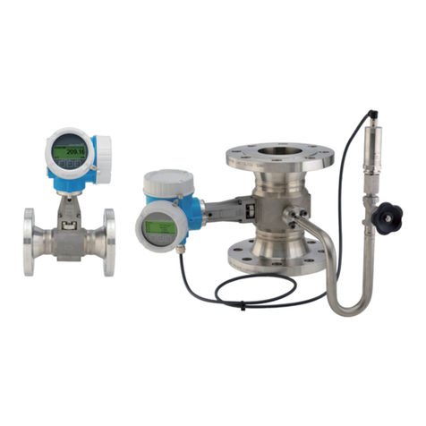
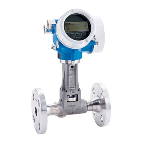
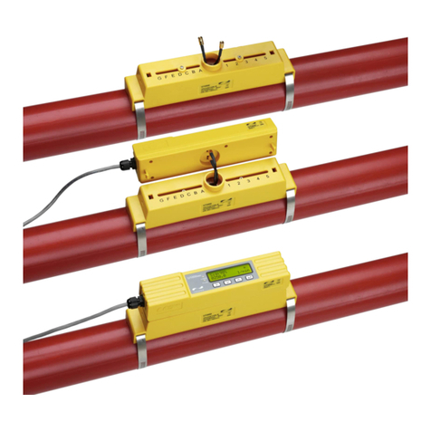
TLV EF200W-C Manual

172-65762M-00(EF200W-CVortexflowmeter)8February2021
EF200W-C
Vortexflowmeter
Copyright©2021byTLVCO.,LTD.
Allrightsreserved

EF200W-C
2
Tableofcontents
Aboutthisdocument
Symbols
Functionandsystemdesign
Measuringprinciple
Measuringsystem
Input
Measuredvariable
Measuringrange
Operableflowrange
Output
Outputsignal
Signalonalarm
Load
Lowflowcutoff
Galvanicisolation
Protocol-specificdata
Powersupply
Terminalassignment
Supplyvoltage
Powerconsumption
Currentconsumption
Powersupplyfailure
Electricalconnection
Potentialequalization
Terminals
Cableentries
Cablespecification
Overvoltageprotection
Performancecharacteristics
Referenceoperatingconditions
Maximummeasurederror
Repeatability
Responsetime
Influenceofambienttemperature
Installation
Mountinglocation
Orientation
Inletandoutletruns
Mountingkitfordisc(waferversion)
Lengthofconnectingcable
Mountingthetransmitterhousing
Environment
Ambienttemperaturerange
Storagetemperature
Climateclass
Degreeofprotection
Vibration-andshock-resistance
Electromagneticcompatibility(EMC)
Process
Mediumtemperaturerange
Pressure-temperatureratings
Nominalpressureofsensor
Pressureloss
Thermalinsulation
Mechanicalconstruction
DimensionsinSIunits
DimensionsinUSunits
Weight
Materials
Operability
Operatingconcept
Languages
Localoperation
Remoteoperation
Certificatesandapprovals
CEmark
RCM-ticksymbol
HARTcertification
PressureEquipmentDirective
Experience
Otherstandardsandguidelines
Orderinginformation
Productgenerationindex
Supplementarydocumentation
Standarddocumentation
Registeredtrademarks
ProductWarranty
Service

EF200W-C
3
About this document
slobmys lacirtcelEslobmyS
Symbol Meaning
Directcurrent
Alternatingcurrent
Directcurrentandalternatingcurrent
Groundconnection
Agroundedterminalwhich,asfarastheoperatorisconcerned,isgroundedviaa
groundingsystem.
ProtectiveEarth(PE)
Aterminalwhichmustbeconnectedtogroundpriortoestablishinganyother
connections.
Thegroundterminalsaresituatedinsideandoutsidethedevice:
• Innergroundterminal:Connectstheprotectivearthtothemainssupply.
• Outergroundterminal:Connectsthedevicetotheplantgroundingsystem.
Symbols for certain types of information
Symbol Meaning
Permitted
Procedures,processesoractionsthatarepermitted.
Preferred
Procedures,processesoractionsthatarepreferred.
Forbidden
Procedures,processesoractionsthatareforbidden.
Tip
Indicatesadditionalinformation.
Referencetodocumentation.
AReferencetopage.
Referencetographic.
Visualinspection.
Symbols in graphics
Symbol Meaning
1,2,3,... Itemnumbers
1. , 2. , 3. ,… Seriesofsteps
A,B,C,... Views
A-A,B-B,C-C,... Sections
-Hazardousarea
Flowdirection

EF200W-C
4
Function and system design
Measuring principle VortexmetersworkontheprincipleoftheKarmanvortexstreet.Whenfluidflowspastabluffbody,
vorticesarealternatelyformedonbothsideswithoppositedirectionsofrotation.Thesevorticeseach
generatealocallowpressure.Thepressurefluctuationsarerecordedbythesensorandconvertedto
electricalpulses.Thevorticesdevelopveryregularlywithinthepermittedapplicationlimitsofthe
device.Therefore,thefrequencyofvortexsheddingisproportionaltothevolumeflow.
A0033465
Samplegraphic
Thecalibrationfactor(K-factor)isusedastheproportionalconstant:
K-Factor = Pulses
Unit Volume [m³]
Withintheapplicationlimitsofthedevice,theK-factoronlydependsonthegeometryofthedevice.
ItisforRe>20000:
• Independentoftheflowvelocityandthefluidpropertiesviscosityanddensity
• Independentofthetypeofsubstanceundermeasurement:steam,gasorliquid
Theprimarymeasuringsignalislineartotheflow.Afterproduction,theK-factorisdeterminedin
thefactorybymeansofcalibration.Itisnotsubjecttolong-timedriftorzero-pointdrift.
Thedevicedoesnotcontainanymovingpartsanddoesnotrequireanymaintenance.
The capacitance sensor
Thesensorofavortexflowmeterhasamajorinfluenceontheperformance,robustnessand
reliabilityoftheentiremeasuringsystem.
TherobustDSCsensoris:
• burst-tested
• testedagainstvibrations
• testedagainstthermalshock(thermalshocksof150K/s)
Themeasuringdeviceusesthetried-and-tested,capacitancemeasuringtechnology
whichisalreadyinuseinover450000measuringpointsworldwide.Thankstoits
design,thecapacitancesensorisalsoparticularlymechanicallyresistanttotemperatureshocksand
pressureshocksinsteampipelines.

EF200W-C
5
Temperature measurement
Themeasuringdevicecanalsomeasurethetemperatureofthemedium.
ThetemperatureismeasuredviaPt1000temperaturesensors.Thesearelocatedinthepaddleof
theDSCsensorandarethereforeinthedirectvicinityofthefluid.
1
A0034068
1 DSCsensor
Lifelong calibration
Experiencehasshownthatrecalibratedmeasuringdevicesdemonstrateaveryhighdegreeof
stabilitycomparedtotheiroriginalcalibration:Therecalibrationvalueswereallwithintheoriginal
measuringaccuracyspecificationsofthedevices.Thisappliestothemeasuredvolumeflow,the
device'sprimarymeasuredvariable.
Varioustestsandsimulationhaveshownthatoncetheradiioftheedgesonthebluffbodyareless
than1mm(0.04in),theresultingeffectdoesnothaveanegativeimpactonaccuracy.
Iftheradiioftheedgesonthebluffbodydonotexceed1mm(0.04in),thefollowinggeneral
statementsapply(inthecaseofnon-abrasiveandnon-corrosivemedia,suchasinmostwaterand
steamapplications):
• Themeasuringdevicedoesnotdisplayanoffsetinthecalibrationandtheaccuracyisstill
guaranteed.
• Alltheedgesonthebluffbodyhavearadiusthatistypicallysmallerinsize.Asthemeasuring
devicesarenaturallyalsocalibratedwiththeseradii,themeasuringdeviceremainswithinthe
specifiedaccuracyratingprovidedthattheadditionalradiusthatisproducedasaresultofwear
andteardoesnotexceed1mm(0.04in).
Consequently,itcanbesaidthattheproductlineofferslifelongcalibrationifthemeasuringdeviceis
usedinnon-abrasiveandnon-corrosivemedia.
Air and industrial gases
Themeasuringdeviceenablesuserstocalculatethedensityandenergyofairandindustrialgases.
Thecalculationsarebasedontime-testedstandardcalculationmethods.Itispossibleto
automaticallycompensatefortheeffectofpressureandtemperatureviaanexternalorconstant
value.
Thismakesitpossibletooutputtheenergyflow,standardvolumeflowandmassflowofthe
followinggases:
• Singlegas
• Gasmixture
• Air
• User-specificgas
Fordetailedinformationontheparameters,seetheOperatingInstructions.→Seepage52

EF200W-C
6
Measuring system Thedeviceconsistsofatransmitterandasensor.
Twodeviceversionsareavailable:
• Compactversion‒transmitterandsensorformamechanicalunit.
• Remoteversion-transmitterandsensoraremountedinseparatelocations.
Transmitter
EF200-C Deviceversionsandmaterials:
• Compactorremoteversion,aluminumcoated:
Aluminum,AlSi10Mg,coated
Configuration:
• Viafour-linelocaldisplaywithkeyoperationorviafour-line,
• Viaoperatingtools
A0013471
Sensor
EF200W-C Disc(waferversion):
• Nominaldiameterrange:DN15to150(½to6")
• Materials:
Measuringtubes:stainlesssteel,CF3M/1.4408
A0009922
Input
Measured variable Direct measured variables
Ordercodefor"Sensorversion;DSCsensor;measuringtube"
Description Measuredvariable
Mass;316L;316L(integratedtemperaturemeasurement) • Volumeflow
• Temperature
Mass;316L;316L(integratedtemperaturemeasurement) • Correctedvolumeflow
• Massflow
• Calculatedsaturatedsteampressure
• Energyflow
• Heatflowdifference
• Specificvolume
• Degreesofsuperheat
Description Measuredvariable
Calculated measured valuables

EF200W-C
7
Measuring range Themeasuringrangeisdependentonthenominaldiameter,thefluidandenvironmentalinfluences.
Thefollowingspecifiedvaluesarethelargestpossibleflowmeasuringranges(QmintoQmax)
foreachnominaldiameter.Dependingonthefluidpropertiesandenvironmentalinfluences,
themeasuringrangemaybesubjecttoadditionalrestrictions.Additionalrestrictionsapply
toboththelowerrangevalueandtheupperrangevalue.
FlowmeasuringrangesinSIunits
DN
[mm]
Liquids
[m³/h]
Gas/steam
[m³/h]
15 0.06to4.9 0.3to25
25 0.18to15 0.9to130
40 0.45to37 2.3to310
50 0.75to62 3.8to820
80 1.7to140 8.5to1800
100 2.9to240 15to3200
150 6.7to540 33to7300
FlowmeasuringrangesinUSunits
DN Liquids Gas/steam
[in] [ft³/min] [ft³/min]
½ 0.035to2.9 0.18to15
1 0.11to8.8 0.54to74
1½ 0.27to22 1.3to180
2 0.44to36 2.2to480
3 1to81 5to1100
4 1.7to140 8.7to1900
6 3.9to320 20to4300

EF200W-C
8
Flow velocity
Di
v,Q
A0033469
DiInternaldiameterofmeasuringtube(correspondstodimensionK→Seepage34)
v Velocityinmatingpipe
Q Flow
TheinternaldiameterofmeasuringtubeDiisdenotedinthedimensionsasdimension
K.→Seepage34.
Calculationofflowvelocity:
v[m/s]=
³
]h/m[Q·4
π·D [m]
i²·1
3600[s/h]
v[ /s]= 4 ·Q[ /min]ft³
π·D [ft]
i²·1
60[s/min]
A0034301
Lower range value
Arestrictionappliestothelowerrangevalueduetotheturbulentflowprofile,whichonlyoccurs
withReynoldsnumbersgreaterthan5000.TheReynoldsnumberisdimensionlessandindicatesthe
ratiooftheinertiaforceofafluidtoitsviscousforcewhenflowingandisusedasacharacteristic
variableforpipeflows.InthecaseofpipeflowswithReynoldsnumberslessthan5
000,periodic
vorticesarenolongergeneratedandflowratemeasurementisnolongerpossible.
TheReynoldsnumberiscalculatedasfollows:
Re =4·Q[m
³
/s]· [kg/m
³
]ρ
·D [m]·µ[Pa·s]π
i
Re =4·Q[ft³/s]· [lbm/ft³]ρ
·D [ft]·µ[lbf·s/ft ]π
i
²
A0034291
Re Reynoldsnumber
Q Flow
DiInternaldiameterofmeasuringtube(correspondstodimensionK→Seepage34)
µ Dynamicviscosity
ρ Density
TheReynoldsnumber,5000togetherwiththedensityandviscosityofthefluidandthenominal
diameter,isusedtocalculatethecorrespondingflowrate.

EF200W-C
9
Q [m /h]=
Re=5000 ³
5000 [Pa· ·D [m]· ·s]
i
πμ
· 3600[s/h]
4 [kg/m ]·³ρ
Q [ /h]=
Re=5000 ³
5000 [lbf· ·D [ft]· ·s/ft ]
i
²πμ
· 60[s/min]
4 [lbm/ ]· ³ρ
A0034302
QRe=5000 FlowrateisdependentontheReynoldsnumber
DiInternaldiameterofmeasuringtube(correspondstodimensionK→Seepage34)
µ Dynamicviscosity
ρ Density
Themeasuringsignalmusthaveacertainminimumsignalamplitudesothatthesignalscanbe
evaluatedwithoutanyerrors.Usingthenominaldiameter,thecorrespondingflowcanalsobe
derivedfromthisamplitude.Theminimumsignalamplitudedependsonthesettingforthe
sensitivityoftheDSCsensor(s),thesteamquality(x)andtheforceofthevibrationspresent(a).The
valuemfcorrespondstothelowestmeasurableflowvelocitywithoutvibration(nowetsteam)ata
densityof1kg/m3(0.0624lbm/ft^3).Thevaluemfcanbesetintherangefrom
6to20m/s(1.8to6ft/s)(factorysetting12m/s(3.7ft/s))withtheSensitivityparameter(value
range1to9,factorysetting5).
v [m/s]=max
AmpMin mf[m/s]
x²
AmpMin x² ρ
³m]/gk[1
ρ³m]/gk[
A0034303
vAmpMin Minimummeasurableflowvelocitybasedonsignalamplitude
mf Sensitivity
x Steamquality
ρ Density
Q [m /h]=
AmpMin ³
v [m/s]
AmpMin · ·D [m]
i
²
π
· 3600[s/h]
4· ³]m/gk[ρ
³]m/gk[1
Q [ /min]=
AmpMin ³
v[/s]
AmpMin · ·D [ft]
i²π
· 60[s/min]
4· 0.0624[lbm/ ]³
A0034304
QAmpMin Minimummeasurableflowratebasedonsignalamplitude
vAmpMin Minimummeasurableflowvelocitybasedonsignalamplitude
DiInternaldiameterofmeasuringtube(correspondstodimensionK→Seepage34)
ρ Density

EF200W-C
10
TheeffectivelowerrangevalueQLowisdeterminedusingthelargestofthethreevaluesQmin,
Q [m /h]=max
Low ³
Q [m /h]
min
³
Q [m /h]
Re=5000 ³
Q [m /h]
AmpMin ³
Low ³
Q [ /min]
min
Q [ /min]
Re=5000
Q [ /min]
AmpMin
A0034313
QLow Effectivelowerrangevalue
Qmin Minimummeasurableflowrate
Q=5000 FlowrateisdependentontheReynoldsnumber
QAmpMin Minimummeasurableflowratebasedonsignalamplitude
Upper range value
Themeasuringsignalamplitudemustbebelowacertainlimitvaluetoensurethatthesignalscanbe
evaluatedwithouterror.ThisresultsinamaximumpermittedflowrateQAmpMax:
Q [m /h]=
AmpMax ³
350[m/s] · ·D [m]
i
²
π
· 3600[s/h]
4· ³]m/gk[ρ
³]m/gk[1
Q [ /min]=
AmpMax ³
1148[ /s] · ·D [ft]
i²π
· 60[s/min]
4· 0.0624[lbm/ ]³
A0034316
QAmpMax Maximummeasurableflowratebasedonsignalamplitude
DiInternaldiameterofmeasuringtube(correspondstodimensionK→Seepage34)
ρ Density
Forgasapplications,anadditionalrestrictionappliestotheupperrangevaluewithregardtothe
Machnumberinthemeasuringdevice,whichmustbelessthan0.3.TheMachnumberMadescribes
theratiooftheflowvelocityvtothesoundvelocitycinthefluid.
Ma= v[m/s]
c[m/s]
Ma=
A0034321
QRe=5000andQAmpMin.

EF200W-C
11
Ma Machnumber
vFlowvelocity
c Soundvelocity
Thecorrespondingflowratecanbederivedusingthenominaldiameter.
Q [m /h]=
Ma=0.3 ³0.3 ·c[m/s]· ·D [m]
i
²
π
4· 3600[s/h]
Q [ /min]=
Ma=0.3 ³0.3 ·c[ft/s]· ·D [ft]
i²π
4· 60[s/min]
A0034337
QMa=0.3 RestrictedupperrangevalueisdependentonMachnumber
c Soundvelocity
DiInternaldiameterofmeasuringtube(correspondstodimensionK→Seepage34)
ρ Density
TheeffectiveupperrangevalueQHighisdeterminedusingthesmallestofthethreevalues
QmaxʼQAmpMaxandQMa=0.3.
Q [m /h]=min
High ³
Q [m /h]
max
³
Q [m /h]
AmpMax ³
Q [m /h]
Ma=0.3 ³
High ³
Q [ /min]
max
Q [ /min]
AmpMax
Q [ /min]
Ma=0.3
A0034338
QHigh Effectiveupperrangevalue
Qmax Maximummeasurableflowrate
QAmpMax Maximummeasurableflowratebasedonsignalamplitude
QMa=0.3 RestrictedupperrangevalueisdependentonMachnumber
Forliquids,theoccurrenceofcavitationmayalsorestricttheupperrangevalue.
Operable flow range Thevalue,whichistypicallyupto49:1,mayvarydependingontheoperatingconditions(ratio
betweenupperrangevalueandlowerrangevalue)

EF200W-C
12
Output
Output signal Current output
Currentoutput1 4-20mA(passive)
Resolution <1µA
Damping Adjustable:0.0to999.9s
Assignablemeasured
variables
• Volumeflow
• Correctedvolumeflow
• Massflow
• Flowvelocity
• Temperature
• Pressure
• Calculatedsaturatedsteampressure
• Totalmassflow
• Energyflow
• Heatflowdifference
Pulse/frequency/switch output
Function Canbesettopulse,frequencyorswitchoutput
Version Passive,opencollector
Maximuminputvalues • DC35V
• 50mA
Voltagedrop • For侑2mA:2V
• For10mA:8V
Residualcurrent 侑0.05mA
Pulseoutput
Pulsewidth Adjustable:5to2000ms
Maximumpulserate 100Impulse/s
Pulsevalue Adjustable
Assignablemeasured
variables
• Massflow
• Volumeflow
• Correctedvolumeflow
• Totalmassflow
• Energyflow
• Heatflowdifference
Frequencyoutput
Outputfrequency Adjustable:0to1000Hzv
Damping Adjustable:0to999s
Pulse/pauseratio 1:1
Assignablemeasured
variables
• Volumeflow
• Correctedvolumeflow
• Massflow
• Flowvelocity
• Temperature
• Calculatedsaturatedsteampressure
• Totalmassflow
• Energyflow
• Heatflowdifference
• Pressure

EF200W-C
13
Switchoutput
Switchingbehavior Binary,conductiveornon-conductive
Switchingdelay Adjustable:0to100s
Numberofswitching
cycles
Unlimited
Assignablefunctions • Off
•On
• Diagnosticbehavior
• Limitvalue
• Volumeflow
• Correctedvolumeflow
• Massflow
• Flowvelocity
• Temperature
• Calculatedsaturatedsteampressure
• Totalmassflow
• Energyflow
• Heatflowdifference
• Pressure
• Reynoldsnumber
• Totalizer1-3
• Status
• Statusoflowflowcutoff
Signal on alarm Dependingontheinterface,failureinformationisdisplayedasfollows:
Current output 4 to 20 mA
4to20mA
Failuremode Choosefrom:
• 4to20mAinaccordancewithNAMURrecommendationNE43
• 4to20mAinaccordancewithUS
• Min.value:3.59mA
• Max.value:22.5mA
• Freelydefinablevaluebetween:3.59to22.5mA
• Actualvalue
• Lastvalidvalue
Pulse/frequency/switch output
Pulseoutput
Failuremode Nopulses
Frequencyoutput
Failuremode Choosefrom:
• Actualvalue
• 0Hz
• Definedvalue:0to1250Hz
Switchoutput
Failuremode Choosefrom:
• Currentstatus
• Open
• Closed

EF200W-C
14
Local display
Plaintextdisplay Withinformationoncauseandremedialmeasures
StatussignalasperNAMURrecommendationNE107
Interface/protocol
• Viadigitalcommunication:
• HARTprotocol
• Viaserviceinterface
CDIserviceinterface
Plaintextdisplay Withinformationoncauseandremedialmeasures
Additionalinformationonremoteoperation→Seepage50
Load Loadforcurrentoutput:0to500Ω,dependingontheexternalsupplyvoltageofthepowersupply
unit
Calculation of the maximum load
Dependingonthesupplyvoltageofthepowersupplyunit(US),themaximumload(RB)including
lineresistancemustbeobservedtoensureadequateterminalvoltageatthedevice.Indoingso,
observetheminimumterminalvoltage
• ForUS=17.9to18.9V:RB侑(US-17.9V):0.0036A
• ForUS=18.9to24V:RB侑(US-13V):0.022A
• ForUS=侒24V:RB侑500Ω
0
100
200
300
400
500
16 18 20 22 24 26 28 30 32 U [V]
S
RB[Ω]
34 36
A0013563
Operatingrange
Samplecalculation
Supplyvoltageofpowersupplyunit:US=19V
Maximumload:RB侑(19V-13V):0.022A=273Ω

EF200W-C
15
Low flow cut off Theswitchpointsforlowflowcutoffarepresetandcanbeconfigured.
Galvanic isolation Allinputsandoutputsaregalvanicallyisolatedfromoneanother.
Protocol-specific data HART
ManufacturerID 0x11
DevicetypeID 0x0038
HARTprotocolrevision 7
Devicedescriptionfiles
(DTM,DD)
ConsultTLVformoreinformation.
HARTload • Min.250Ω
• Max.500Ω
Power supply
Terminal assignment Transmitter
Connectionversions
3 4 1 2
C
+‒+‒
AB
A0033475
Maximumnumberofterminals
Terminals1to4:
Withoutintegratedovervoltageprotection
A
B
C
Output1(passive):supplyvoltageandsignaltransmission
Output2(passive):supplyvoltageandsignaltransmission
Groundterminalforcableshield
Terminalnumbers
Output1 Output2
1(+) 2(-) 3(+) 4(-)
4-20mAHART(passive) Pulse/frequency/switch
output(passive)
Output1mustalwaysbeused;output2isoptional.

EF200W-C
16
Connecting cable for remote version
Transmitterandsensorconnectionhousing
Inthecaseoftheremoteversion,thesensorandtransmitteraremountedseparatelyfromon
anotherandconnectedbyaconnectingcable.Connectionisperformedviathesensorconnection
housingandthetransmitterhousing.
Terminalsarealwaysusedtoconnecttheconnectingcableinthesensorconnectionhousing
(tighteningtorquesforscrewsforcablestrainrelief:1.2to1.7Nm).
Connectingcable
+‒
+‒
2
1
1
2
1234
1234
GNYEWHBN
A0033476
Terminalsforconnectioncompartmentinthetransmitterwallholderandthesensorconnectionhousing
1 Terminalsforconnectingcable
2 Groundingviathecablestrainrelief
Terminalnumber Assignment Cablecolor
Connectingcable
1 Supplyvoltage Brown
2 Grounding White
3 RS485(+) Yellow
4 RS485(‒) Green

EF200W-C
17
Supply voltage Transmitter
Anexternalpowersupplyisrequiredforeachoutput.
Supplyvoltageforacompactversionwithoutalocaldisplay1)
Output Minimum
terminalvoltage2) Maximum
terminalvoltage
4-20mAHART,pulse/frequency/switchoutput 侒DC12V DC35V
1) Ineventofexternalsupplyvoltageofthepowersupplyunitwithload
2) Theminimumterminalvoltageincreasesiflocaloperationisused:seethefollowingtable
3) Voltagedrop2.2to3Vfor3.59to22mA
Increaseinminimumterminalvoltage
Display;operation Increaseinminimum
terminalvoltage
Localoperation +DC1V
Power consumption Transmitter
Ordercodefor"Output;input" Maximumpowerconsumption
4-20mAHART,pulse/
frequency/switchoutput
• Operationwithoutput1:770mW
• Operationwithoutput1and2:2770mW
Current consumption Current output
Forevery4-20mAor4-20mAcurrentoutput:3.6to22.5mA
IftheoptionDefinedvalueisselectedintheFailuremodeparameter:3.59to22.5mA
Current output
3.59to22.5mA
IInternalcurrentlimiting:max26mA

EF200W-C
18
Power supply failure • Totalizersstopatthelastvaluemeasured.
• Dependingonthedeviceversion,theconfigurationisretainedinthedevicememoryorinthe
pluggabledatamemory(HistoROMDAT).
• Errormessages(incl.totaloperatedhours)arestored.
Electrical connection Connecting the transmitter
1
1
A0033480
1 Cableentriesforinputs/outputs
Remote version connection
Connectingcable
3
1
2
A0033481
Connectingcableconnection
1 Wallholderwithconnectioncompartment(transmitter)
2 Connectingcable
3 Sensorconnectionhousing
Terminalsarealwaysusedtoconnecttheconnectingcableinthesensorconnectionhousing
(tighteningtorquesforscrewsforcablestrainrelief:1.2to1.7Nm).

EF200W-C
19
Connection examples
Currentoutput4-20mA
23
4...20mA
41
5
A0028762
Connectionexamplefor4to20mAHARTcurrentoutput(passive)
1 Automationsystemwithcurrentinput(e.g.PLC)
2 Powersupply
3 Cableshieldprovidedatoneend.ThecableshieldmustbegroundedatbothendstocomplywithEMC
requirements;observecablespecifications
4 Analogdisplayunit:observemaximumload
5 Transmitter
Pulse/frequency output
12
3
12345
A0028761
Connectionexampleforpulse/frequencyoutput(passive)
1 Automationsystemwithpulse/frequencyinput(e.g.PLC)
2 Powersupply
3 Transmitter:Observeinputvalues
Switch output
12
3
A0028760
Connectionexampleforswitchoutput(passive)
1 Automationsystemwithswitchinput(e.g.PLC)
2 Powersupply
3 Transmitter:Observeinputvalues

EF200W-C
20
Potential equalization Requirements
Pleaseconsiderthefollowingtoensurecorrectmeasurement:
• Sameelectricalpotentialforthefluidandsensor
• Remoteversion:sameelectricalpotentialforthesensorandtransmitter
• Company-internalgroundingconcepts
• Pipematerialandgrounding
Terminals • Fordeviceversionwithoutintegratedovervoltageprotection:plug-inspringterminalsforwire
cross-sections0.5to2.5mm2(20to14AWG)
• Fordeviceversionwithintegratedovervoltageprotection:screwterminalsforwirecross-sections
0.2to2.5mm2(24to14AWG)
Cable entries
• Threadforcableentry:
G½"
Cable specification Permitted temperature range
• Theinstallationguidelinesthatapplyinthecountryofinstallationmustbeobserved.
• Thecablesmustbesuitablefortheminimumandmaximumtemperaturestobeexpected.
Signal cable
Currentoutput4to20mA
Ashieldedcableisrecommended.Observegroundingconceptoftheplant.
Pulse/frequency/switchoutput
Standardinstallationcableissufficient.
Connecting cable for remote version
Connectingcable
Standardcable 2×2×0.5mm2(22AWG)PVCcablewithcommonshield(2pairs,pair-
stranded)1)
Flameresistance AccordingtoDINEN60332-1-2
Oil-resistance AccordingtoDINEN60811-2-1
Shielding Galvanizedcopper-braid,opt.densityapprox.85%
Cablelength 30m(98ft)
Operatingtemperature Whenmountedinafixedposition:‒50to+105°C(‒58to+221°F);when
1) UVradiationmaycausedamagetotheouterjacketofthecable.Protectthecablefromexposuretosunas
muchaspossible.
Table of contents
Other TLV Measuring Instrument manuals
