TLV EF200 User manual
172-65639M-01 (EF200) 13 April 2018
Vortex Flowmeter
EF200
Copyright © 2018 by TLV CO., LTD.
All rights reserved

172-65639M-01 (EF200) 13 Apr 2018
2
Contents
1. Safety Instructions............................................................................................4
1.1 Correct Usage ............................................................................................................ 4
1.2 Dangers and Notes .................................................................................................... 4
1.3 Operational Safety...................................................................................................... 4
1.4 Installation, Commissioning and Operation ............................................................... 5
1.5 Repairs, Dangerous Chemicals ................................................................................. 5
1.6 Technical Improvements............................................................................................ 5
2. System Description...........................................................................................6
2.1 EF200 Measuring System.......................................................................................... 6
2.2 Steam Dryness Fraction Calculator ........................................................................... 7
3. Mounting and Installation.................................................................................8
3.1 Transport.................................................................................................................... 8
3.2 Degree of Protection .................................................................................................. 8
3.3 Installation Conditions................................................................................................ 9
3.3.1 Upstream and Downstream Sections...................................................................... 9
3.3.2 Flow Conditioner (Rectifier)................................................................................... 10
3.3.3 Installation Orientation .......................................................................................... 11
3.3.4 Pressure Measurement Points.............................................................................. 11
3.3.5 Pipeline Heat Insulation ........................................................................................ 12
3.3.6 Minimum Maintenance Space............................................................................... 12
3.3.7 Ensuring accurate measurements ........................................................................ 12
3.3.8 Other Considerations ............................................................................................ 13
3.4 Mounting the Flowmeter........................................................................................... 14
3.5 Mounting the Transmitter (Remote Version)............................................................ 15
3.6 Transmitter Housing / Display (Mounting/Rotating) ................................................. 16
3.7 Protect the Transmitter Against Direct Sunlight....................................................... 17
4. Electrical Connection......................................................................................18
4.1 Connecting the Transmitter...................................................................................... 18
4.2 Wiring Diagrams....................................................................................................... 19
4.3 Connecting to TLV EC351 Flow Computer and Parameter Settings....................... 20
4.4 Connecting the Remote Version.............................................................................. 21
5. Operation.........................................................................................................23
5.1 Display and Operating Elements.............................................................................. 23
5.1.1 Operating Display.................................................................................................. 23
5.1.2 Navigation view..................................................................................................... 24
5.1.3 Editing view........................................................................................................... 26
5.1.4 Operating elements............................................................................................... 27
5.2 Navigating the Operation Menu (Basic Operation of the Function Matrix) .............. 28
5.2.1 Calling up help text................................................................................................ 29
5.2.2 Disabling write protection via access code ........................................................... 29
5.2.3 Enabling and disabling the keypad lock................................................................ 29
6. Technical Data.................................................................................................30
6.1 Technical Data at a Glance...................................................................................... 30
6.1.1 Application............................................................................................................. 30
6.1.2 Function and System Design................................................................................ 30
6.1.3 Input...................................................................................................................... 30
6.1.4 Output ................................................................................................................... 31
6.1.5 Power Supply........................................................................................................ 32
6.1.6 Performance Characteristics................................................................................. 33
6.1.7 Mechanical Construction....................................................................................... 34
6.1.8 User Interface........................................................................................................ 35
6.2 Remote Transmitter Dimensions.............................................................................. 35
6.3 EF200W Dimensions – Flangeless Connection....................................................... 36
6.4 EF200F Dimensions – Flanged Connection ............................................................ 37
6.5 EF200R Dimensions – Flanged Connection............................................................ 39
6.6 Dimensions of Flow Conditioner (optional) .............................................................. 40

172-65639M-01 (EF200) 13 Apr 2018
3
7. Commissioning................................................................................................42
7.1 Function Check.........................................................................................................42
7.2 Commissioning.........................................................................................................42
7.2.1 Switching on the Measuring Device.......................................................................42
7.2.2 Device Setup..........................................................................................................42
8. Device Functions.............................................................................................43
8.1 Function Matrix .........................................................................................................43
8.2.1 Setting the Operating Language............................................................................44
8.2.2 Operation ...............................................................................................................44
8.2.3 Display: Operation →Display................................................................................45
8.2.4 Totalizer handling: Operation →Totalizer handling...............................................45
8.2.5 Medium selection: Setup →Medium selection......................................................46
8.2.6 Current output: Setup →Current output ................................................................47
8.2.7 Pulse/frequency/switch output: Setup →Pulse/frequency/switch output...............48
8.2.8 Display: Setup →Display.......................................................................................51
8.2.9 Output conditioning: Setup →Output conditioning................................................52
8.2.10 Low flow cut off: Setup →Low flow cut off...........................................................52
8.2.11 System units: Setup →Advanced setup →System units....................................53
8.2.12 Medium properties: Setup →Advanced setup →Medium properties .................55
8.2.13 Gas composition: Setup →Advanced setup →Medium properties →Gas
composition..........................................................................................................56
8.2.14 External compensation: Setup →Advanced setup →External compensation....56
8.2.15 Sensor adjustment: Setup →Advanced setup →Sensor adjustment.................57
8.2.16 Totalizer 1 to 3: Setup →Advanced setup →Totalizer 1 to 3 .............................58
8.2.17 Display: Setup →Advanced setup →Display.....................................................58
8.2.18 Configuration backup display: Setup →Advanced setup →Configuration backup
display..................................................................................................................59
8.2.19 Administration: Setup →Advanced setup →Administration ...............................60
8.2.20 Diagnostics...........................................................................................................61
8.2.21 Event logbook: Diagnostics →Event logbook .....................................................61
8.2.22 Device information: Diagnostics →Device information .......................................61
8.2.23 Measured values: Diagnostics →Measured values ............................................62
8.2.24 Output values: Diagnostics →Measured values →Output values......................63
8.2.25 Simulation: Diagnostics →Simulation .................................................................63
8.2.26 Expert...................................................................................................................64
9. Configuration of the Transmitter Housing (Display Unit) .............................65
10. Diagnostics and troubleshooting.................................................................66
10.1 Troubleshooting......................................................................................................66
10.2 Diagnostic message (Error message)....................................................................67
10.3 Overview of diagnostic information.........................................................................69
10.4 Overview of information events ..............................................................................72
11. Flow Rate Data...............................................................................................73
11.1 Flow Rate for Saturated Steam (kg/h)....................................................................73
11.2 Flow Rate for Air or Water (m3/h) ...........................................................................74
11.3 Function Matrix Details...........................................................................................75
12. Product Warranty...........................................................................................76
13. Service............................................................................................................77

172-65639M-01 (EF200) 13 Apr 2018
4
1. Safety Instructions
1.1 Correct Usage
•The EF200 measuring system is used to measure the flow of saturated steam,
superheated steam, air and water. Do not use to measure the flow of toxic,
flammable or otherwise hazardous fluids. Use this system only as intended.
•The primarily measured variables are volume flow and temperature. From
these values, the device can use stored data on density and enthalpy to
calculate and output information such as mass flow and heat flow.
•The manufacturer assumes no liability for damage or other accidents caused
by incorrect use of the instrument.
1.2 Dangers and Notes
All instruments are designed to meet state-of-the-art safety requirements,
have been tested, and have left the factory in a condition in which they are
safe to operate. They can, however, be a source of danger if used incorrectly
or for anything other than the designated use. Consequently, always pay
particular attention to the safety instructions indicated in these Operating
Instructions by the following symbols:
Warning!
This symbol alerts you to a dangerous situation. Failure to avoid this situation
can result in serious or fatal injury.
Caution!
This symbol alerts you to a dangerous situation. Failure to avoid this situation
can result in minor or medium injury.
Note!
This symbol contains information on procedures and other facts which do not
result in personal injury.
1.3 Operational Safety
•The EF200 measuring system complies with EMC requirements of both
IEC/EN 61326 and NAMUR NE 21, and the general safety requirements in
accordance with EN 61010-01.
•EF200 fulfills all requirements for IP 66/67 to EN 60529.
•The appropriate error messages are shown on the LCD display.
•On power failure, the configuration data of the measuring system remain in
the EEPROM. The totalizer remains on the value last shown.
Note!
Warning!
Caution!

172-65639M-01 (EF200) 13 Apr 2018
5
1.4 Installation, Commissioning and Operation
•Mounting, electrical installation, commissioning and maintenance of the
device must be carried out by trained, qualified specialists authorized to
perform such work by the operator of the facility. The specialist must have
read and understand this manual before carrying out its instructions.
•The device may only be operated by personnel who are authorized and
trained by the operator of the facility. Strict compliance with the instructions
in these Operating Instructions is mandatory.
•In the case of corrosive fluids (incl. fluids for cleaning), the user is
responsible for verifying the suitability of the material resistance properties of
wetted parts, as regards their in-process resistance to corrosion; the
manufacturer refuses to accept liability.
•The installer must ensure that the measuring system is correctly wired in
accordance with the wiring diagrams.
Note!
There is no longer any contact protection once the housing cover is removed.
•Observe all local regulations governing the opening and repair of electrical
devices.
1.5 Repairs, Dangerous Chemicals
Warning!
The following procedures must be carried out before an EF200 is sent to TLV
for repair:
NOTE: References to use with hazardous fluids are for customers having
special permission and a signed contract with TLV for hazardous use.
•A note must be enclosed with the instrument, containing a description of the
fault, the application and the chemical and physical properties of the fluid
being measured.
•Remove all fluid residues that may be present. Pay special attention to the
gasket grooves and crevices where fluid may be present. This is especially
important if the fluid is dangerous to health, e.g. flammable, toxic, caustic,
carcinogenic, etc.
•No instrument should be returned to TLV without all dangerous material
being removed first.
Incomplete cleaning of the device may result in waste disposal requirements
or cause harm to personnel (burns, etc.). Any costs arising from this will be
charged to the operator of the device.
1.6 Technical Improvements
The manufacturer reserves the right to modify technical data without prior
notice. Your local TLV Distributor or Sales Office will supply you with all
current information and any updates to this manual.
Note!
Warning!
172-65639M-01 (EF200) 13 Apr 2018
6
2. System Description
The EF200 vortex flowmeter measures the temperature and volumetric flow of
steam, gases and liquids with temperatures in the range of -200 to +400 °C
and at nominal pressures of up to 4.96 MPaG (49.6 barg).
EF200 can measure the volumetric flow rate in operation and can be
programmed to supply the flow rate in mass, energy or corrected volume units
via temperature measurements by the internal temperature sensor.
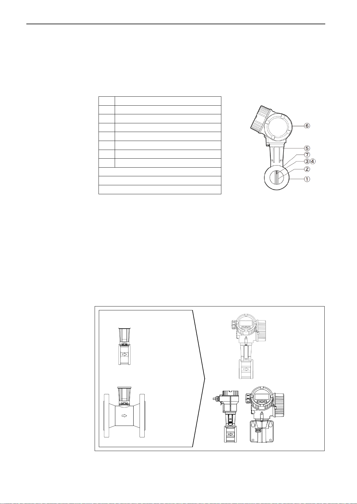
No.
Description
Meter Body
Bluff Body
DSC Sensor (wetted parts)
DSC Sensor (non-wetted parts)
Housing Support
Transmitter Housing
Gasket
Mounting Kit*
Remote Transmitter Mount**
Connection Cable (30 m)**
* Flangeless model only, see 3.5
** Remote version only, see 4.4
2.1 EF200 Measuring System
The measuring system consists of:
•EF200 remote or compact versions
•EF200 flangeless or flanged connection body
In the compact version, the transmitter and sensor form a single mechanical
unit; in the remote version, they are mounted separate from each other. When
the sensor body must be installed in a high or otherwise difficult to reach
location, the remote version allows more accessible transmitter installation.
(See Fig. 1)
Sensor Body
EF200W
Flangeless
DN 15 – 150
Compact
Version
EF200F
Flanged
DN 15 – 300
EF200R
Flanged
DN 25 – 200
Remote
Version
Figure 1
EF200 measuring system

172-65639M-01 (EF200) 13 Apr 2018
7
2.2 Steam Dryness Fraction Calculator
EF200F ordered with the “Steam Dryness Fraction
Calculator” option is not only capable of flow rate
measurement but can also calculate the dryness
fraction of steam.
Measurable range: 80 to 100% (See the figure on
the right for measurement accuracy)
NOTE: Steam dryness fraction is an indication of steam quality. It shows the
ratio of steam by mass in wet saturated steam.
Steam Dryness Fraction (%)=Steam mass flow rate
Steam mass flow rate
+ Water mass flow rate
×100
Caution!
This option cannot be used with EF200W or EF200R.
There are a number of points to consider for the Steam Dryness Fraction
Calculator. Ensure these are met when installing.
Applicable Models
•EF200F (Flanged) DN 25 – 100
Applicable Operating Conditions
•Pressure: 0.1 to 1.0 MPaG (1.0 to 10 barg)
•Temperature: 120 to 185 °C (Saturation temperature for the pressures above)
•Use at a stable pressure and flow rate.
Steam pressure is input in fixed values, therefore correct measurement is
not possible with large pressure fluctuations.
•Make sure the flow rate falls within the measurable range of flow rates at
pressures between 0.1 and 1.0 MPaG (1.0 to 10 barg)
The measurable ranges for flow rate and for steam dryness fraction are
different. Refer to the table below to identify if the Steam Dryness Fraction
Calculator option is applicable.
Caution regarding installation of devices equipped with the Steam
Dryness Fraction Calculator (see 3.3)
•Ensure the required length of straight piping, without using a flow conditioner
•Install on horizontal piping with the display facing downward
Caution!
•When equipped with the Steam Dryness Fraction Calculator function, the
EF200F can be used with steam and water, but cannot be used with air.
•When using the Steam Dryness Fraction Calculator function, the measurement
accuracy for steam mass flow rate will decrease from ±2 °C to ±4 °C.
Measurable flow rates for saturated steam when used with the optional
Steam Dryness Fraction Calculator EF200F (Unit: kg/h)
Size (mm)/DN
25
40
50
80
100
Temp.
(°C)
Pressure
Min. Max. Min. Max. Min. Max. Min. Max. Min. Max.
MPaG
barg
0.1
1
11
66
27
233
44
349
99
872
171
906
120.4
0.2
2
14
96
35
340
57
510
128
1,272
221
1,323
133.7
0.3
3
19
126
45
445
75
668
167
1,666
289
1,731
143.7
0.4
4
23
156
55
548
92
823
206
2,054
356
2,135
151.9
0.5
5
27
185
66
651
109
978
244
2,438
423
2,534
158.9
0.6
6
31
214
76
753
126
1,131
282
2,820
489
2,931
165.0
0.7
7
35
243
86
855
143
1,283
320
3,200
555
3,326
170.5
0.8
8
39
272
96
956
160
1,435
358
3,579
620
3,720
175.4
0.9
9
43
301
106
1,057
177
1,586
396
3,955
686
4,111
179.9
1.0
10
48
329
116
1,158
194
1,737
434
4,333
751
4,503
184.1
Consult TLV for measurable flow rate data in imperial units.
Note!
Caution!
Caution!
80%
90
100
+5
0
-2
-5Measurable Range
Steam
Dryness
Measurement Accuracy of
Steam Dryness
Accuracy %

172-65639M-01 (EF200) 13 Apr 2018
8
3. Mounting and Installation
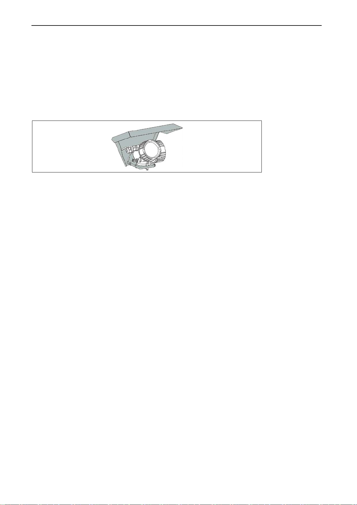
3.1 Transport
•The devices must be transported in the container supplied.
•Devices with nominal diameter 40 to 300 mm (DN 40 to 300) must not be
lifted at the transmitter housing (compact version) or at the connection
housing (remote version) when transporting (see Fig. 2). Use carrier slings
when transporting and put the slings around both process connections.
Avoid chains as these could damage the housing.
Warning!
The center of gravity of the entire measuring device might be higher than the
suspension points of the slings. Therefore, when hoisting, make sure that the
device does not unintentionally turn or slip, as there is the risk of injury if the
device falls.
3.2 Degree of Protection
IP66/67 (EN60529)
Caution!
The devices fulfill all the requirements for IP66/67, Type 4X enclosure.
Compliance with the following points is mandatory following installation in the
field or servicing in order to ensure that IP66/67, Type 4X enclosure protection
is maintained:
•Housing gaskets must be clean and undamaged when inserted in the
gasket groove. The gaskets may need to be dried, cleaned or replaced.
•All housing screws and screw caps must be firmly tightened.
•The cables used for connection must be of the specified outside diameters.
•Firmly tighten the cable entry (see Fig. 3).
•The cables must loop down before they
enter the cable entries (“water trap”, Fig.
3). This arrangement prevents moisture
penetrating the entry. Always install the
measuring device in such a way that the
cable entries do not point up.
•Replace all unused cable entries with
dummy plugs.
•Do not remove the grommet from the
cable entry.
Temperature Ranges
•The maximum allowable ambient and
process temperatures must be
observed (see 6.1.6).
•Ensure both pipeline heat insulation and
mounting position conditions are met
(see 3.3).
Figure 3
Protection Class
IP66/67, Type 4X
enclosure
Warning!
Figure 2
Instructions for
transporting sensors of
sizes 40 -300 mm
Caution!

172-65639M-01 (EF200) 13 Apr 2018
9
3.3 Installation Conditions
A vortex flowmeter requires a fully developed flow profile as a prerequisite for
measuring volume accurately. The following points must therefore be noted
when mounting the EF200 in the pipeline.
Pipe Inner Diameter
When ordering, ensure that the nominal diameter and pipe schedule
(DIN/ANSI/JIS) are correct, since calibration of the flowmeter and therefore the
achievable accuracy of the measuring point are dependent on these
specifications.
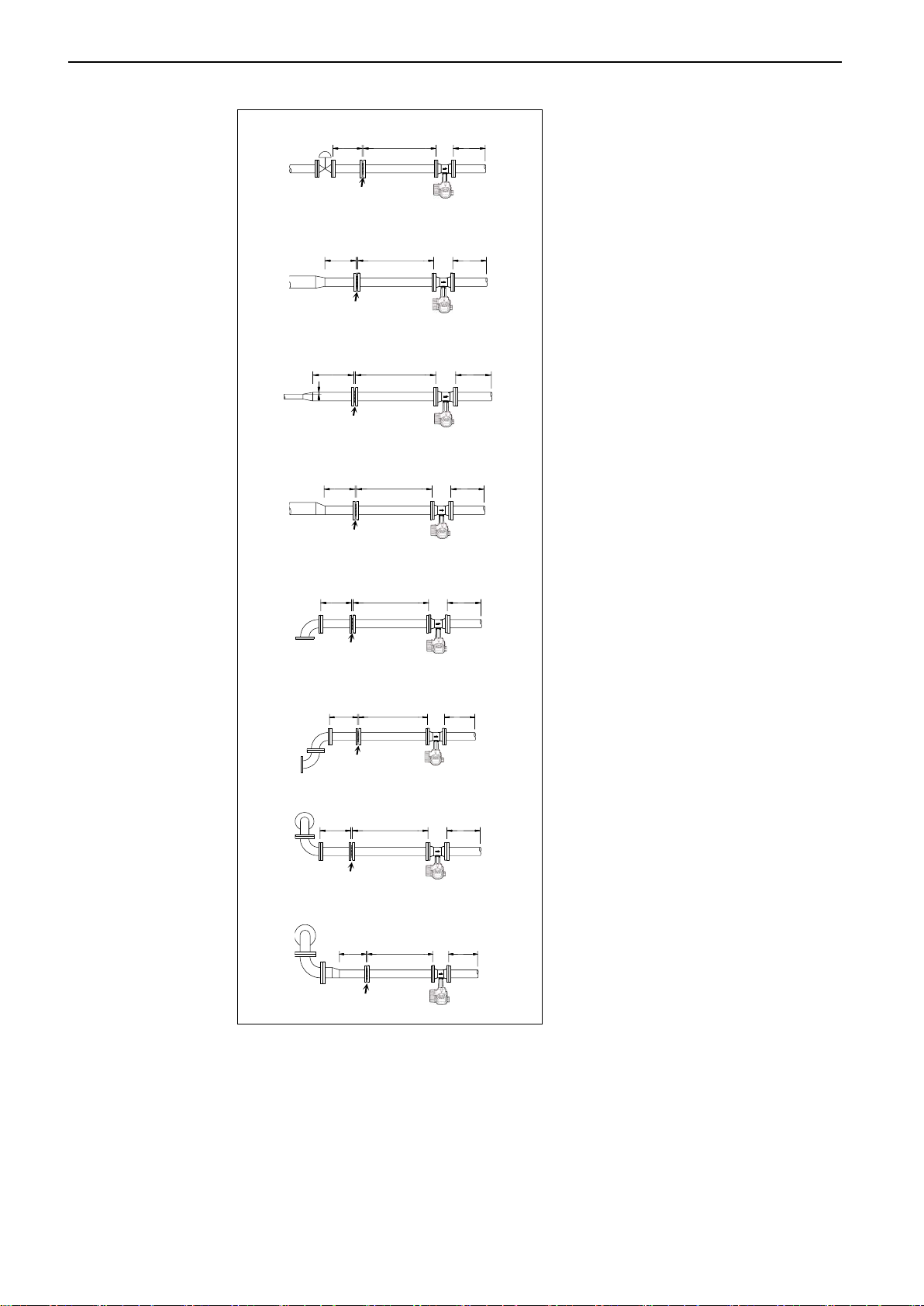
3.3.1 Upstream and Downstream Sections
To ensure an undisturbed flow profile,
the vortex flowmeter should be
mounted up- and downstream of any
flow disturbances such as pipe
elbows, reducers or valves, otherwise
the longest possible straight section
of piping should be between the
disturbance and the flowmeter. The
figures on the right show the
minimum section of straight piping up-
and downstream of the disturbance
as multiples of the nominal diameter
of the pipe (D, see Fig. 4-1). If two or
more flow disturbances are located
upstream, the minimum section of
straight piping upstream is equal to
the sum of each individual
disturbance’s requirements up to a
maximum of 50D.
Example:
For 25 mm diameter piping with one
90° elbow:
20D = 20 ×25 mm = 500 mm,
therefore straight piping length must
be at least 500 mm.
A = Upstream
B = Downstream
D = Nominal Diameter
Control Valve:
Concentric Reducer (Convergent-Pipe) :
Concentric Diffuser (Expansion Pipe):
Eccentric Reducer (Convergent-Pipe):
One 90° Elbow or T-piece:
Two 90° Elbows (2-Dimensional):
Two 90° Elbows (3-Dimensional):
Combination Pipe (Elbows & Eccentric
Reducer, etc.):
AB
50D 5D
AB
15D 5D
AB
18D 5D
AB
25D 5D
AB
20D 5D
AB
25D 5D
AB
40D 5D
AB
50D 5D
Figure 4-1
Upstream
and
downstream
piping
requirements
172-65639M-01 (EF200) 13 Apr 2018
10
3.3.2 Flow Conditioner (Rectifier)
Control Valve and Flow Conditioner:
Concentric Reducer and Flow
Conditioner:
Concentric Diffuser and Flow
Conditioner:
Eccentric Reducer and Flow
Conditioner:
One 90° Elbow or T-piece and Flow
Conditioner:
Two 90° Elbows (2-Dimensional) and
Flow Conditioner:
Two 90° Elbows (3-Dimensional) and
Flow Conditioner:
Combination Pipe (Elbows & Eccentric
Reducer etc.) and Flow Conditioner:
With limited space and large pipes,
it is not always possible to use the
upstream sections shown in Fig. 4-
1. In such cases the specially
developed perforated plate flow
conditioner (see 6.6) can be fitted
as shown on the right (see Fig. 4-
2). The flow conditioner is held
between two piping flanges and
centered with the flange bolts. It
reduces the length of the upstream
section downstream from flow
disturbances to 8D while
maintaining full measurement
accuracy. The total length of
straight piping downstream
becomes 10D to 13D. Note that a
flow conditioner cannot be used in
conjunction with the Steam
Dryness Fraction Calculator option.
A = Upstream
B = Downstream
D = Nominal Diameter
Flow Conditioner
5D 8D 5D
AB
Flow Conditioner
2D 8D 5D
AB
Flow Conditioner
2D+5h 8D 5D
AB
h
Flow Conditioner
5D 8D 5D
AB
2D 8D 5D
AB
Flow Conditioner
5D 8D 5D
AB
Flow Conditioner
5D 8D 5D
AB
Flow Conditioner
5D 8D 5D
AB
Flow Conditioner
Figure 4-2
Upstream and
downstream piping
requirements

172-65639M-01 (EF200) 13 Apr 2018
11
3.3.3 Installation Orientation
The EF200 can be mounted in any direction in
the piping. An arrow on the meter body shows
the direction of flow.
For measuring liquids in vertical pipes, the
meter should be installed with an upwards flow
direction, position A, to make sure pipes are
com
pletely flooded, avoiding partial filling (see
Fig.
5).
For horizontal pipelines, positions B, C and D
are possible (see Fig.
5). With hot piping (e.g.
steam), position C or D must be selected in
order to respect the maximum permissible
ambient temperatur
e at the electronics.
Do not mount the flangeless model
EF200W at
sizes of 100 mm or larger
in position B for use
with fluids
at temperatures equal to or greater
than
200 °C.
Refer to the Technical Data section for
ambient temperatures (see 6.1.6).
Caut
ion!
For use with the Steam Dryness Fraction
Calculator option, ensure the flowmeter is
mounted in position C.
A
B
C
D
3.3.4 Pressure Measurement Points
If a pressure measuring point is installed
after the device, ensure that there is a
large enough distance between the
device and the measuring point so that
there are no negative effects on vortex
formation in the sensor.
(see Fig. 6)
D = Nominal Diameter
Down stream
3D –5D
Figure 6
Mounting pressure
sensors
Figure 5
Installation position
Caution!
172-65639M-01 (EF200) 13 Apr 2018
12
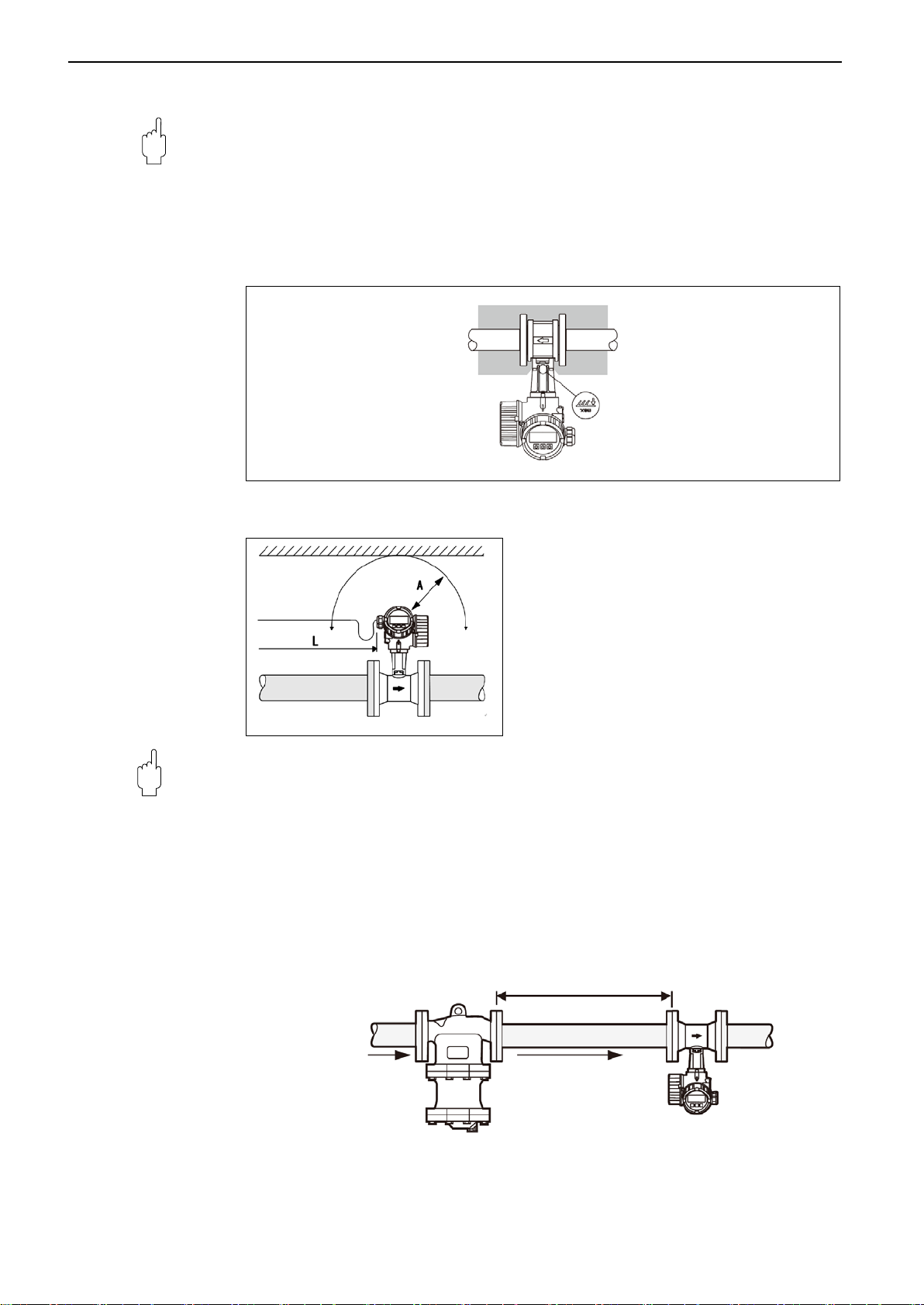
3.3.5 Pipeline Heat Insulation
Caution!
When insulating, please ensure that a sufficiently large area of the housing
support is exposed. The uncovered part serves as a radiator and protects the
electronics from overheating (or undercooling).
The maximum insulation height permitted is illustrated in Figure 7 (marked
“max.” with a limiting line). These apply to both the compact version and the
sensor in the remote version, as well as all installation orientations.
3.3.6 Minimum Maintenance Space
When servicing, it is necessary to
remove the transmitter housing from the
housing support.
When installing in the piping, be sure to
secure the following cable lengths and
minimum maintenance space:
•Minimum maintenance space in all
directions: A = 100 mm
•Cable length required: L + 150 mm
Caution!
Removing the transmitter from the housing support is to be carried out by
qualified TLV appointed service personnel only!
3.3.7 Ensuring accurate measurements
In some cases where steam is mixed with condensate, it may not be possible
to obtain accurate flow rate measurements.
To remove these causes for concern about flow rate measurements, it is
recommended to install a separator upstream of the flowmeter.
Saturated steam
without droplets
Wet steam
with droplets
50 ×D
Figure 8
Minimum spacing for
mounting and removing
the transmitter housing
Caution!
Figure 7
Pipeline insulation
flangeless/flanged
version
Caution!
172-65639M-01 (EF200) 13 Apr 2018
13
3.3.8 Other Considerations
Vibrations
The correct operation of the measuring system is not influenced by plant
vibrations up to 1 g, 10 to 500 Hz. Consequently, the sensors require no
special measures for attachment. If higher levels of vibration are expected, be
sure to secure piping before and after the flow meter.
Preventing Excessive Flow
Caution!
To ensure long service life for the flowmeter, excessive instantaneous/
periodical flow rates should be held below the flow meter’s maximum flow rate.
Failing to do so might result in damage to the sensor. Special care is
necessary for steam at startup when the pressure is low, or when a valve is
opened rapidly, such as by a solenoid valve, as excessive instantaneous flow
rates often occur.
Pulsating Influences
The ability of the flowmeter to measure correctly may be adversely affected if
there are large variations of pressure or pulsating pressure from compressors
and/or soot blowers. Use the procedures below to minimize pulsating
pressures:
•Move the source of the pulsations to the downstream side of the flowmeter.
Alternatively, put as much distance as possible between the source and the
flowmeter.
•Install a pulsation dampening device, such as a chamber.
•Close the valves before and after the flowmeter when there is no flow.
(This is to prevent false non-zero readings under zero-flow conditions.)
Prevent Mixed Phase Flow
This flowmeter is designed to measure both gases and liquids. However,
accurate measurement cannot be guaranteed when gases and liquids are
mixed together (i.e. gas-liquid mixed phase flow).
Ensure Pipe is Flooded
When measuring liquids ensure that the pipe is flooded, as this will have an
influence on the accuracy of flow rate measurements.
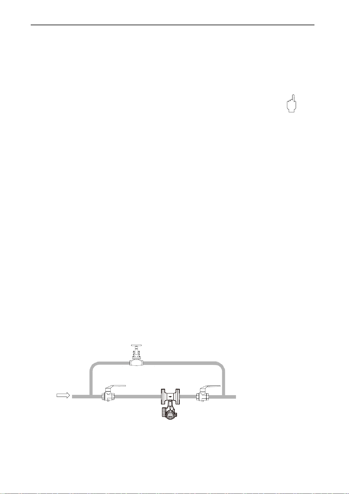
Bypass Lines
The installation of bypass lines can facilitate maintenance and inspections.
When installing a bypass line, use upstream and downstream valves of a type
that does not disturb the flow profile, and secure sufficient length of straight pipe.
EF200
Bypass Valve
Ball Valve
Direction of
Flow
Ball Valve
Caution!

172-65639M-01 (EF200) 13 Apr 2018
14
3.4 Mounting the Flowmeter
Warning!
Note the following points before installing the flowmeter:
•Remove all packaging used for transport and protective coverings from the
flowmeter before installing the flowmeter in the pipeline.
•Ensure that the inner diameters of the gaskets are identical to or larger than
those of the meter body and process piping. Gaskets that protrude into the
flow affect vortex formation behind the bluff body and lead to inaccurate
measurement. Therefore, the gaskets delivered by TLV come with a slightly
larger inner diameter than the measuring pipe.
•Confirm the gaskets are not dirty or damaged.
•Ensure that the direction of the arrow on the sensor body matches the flow
direction (direction of medium flow in the piping).
•Mount the flowmeter or rotate the transmitter housing so that the cable
entries do not face upward.
Mounting EF200 Flangeless Version
Mounting the flangeless body is carried out using a mounting set (see Fig. 9)
Caution!
By tightening the bolts (tie rods) after fitting the centering rings to the flange
rims on the meter body, it is possible to align the meter body with the piping
and fill the space between the bolts (tie rods) and the meter body. However
the centering rings are not secured to the meter body.
Gasket
Centering
ring
Bolt (tie rod) set
Figure 9
Mounting the EF200
flangeless version
Caution!
Warning!

172-65639M-01 (EF200) 13 Apr 2018
15
3.5 Mounting the Transmitter (Remote Version)
Where the flowmeter body is installed on piping in a high position or in cases
where there is poor accessibility to the display, the remote transmitter display
may be installed in an easily visible location.
The transmitter can be mounted in the following ways:
•Wall mounting (Fig. 10.A)
•Pipe mounting (with optional pipe mounting kit) (Fig. 10.B)
Caution!
Install the transmitter in a location out of direct sunlight and with an ambient
temperature range of -40 to +80 °C. (See 3.7)
However, the display performance of the LCD may be affected or it may be
difficult to read the display if the ambient temperature is below -10°C or above
+60°C.
A: Wall Mounting
B: Pipe Mounting
Unit: mm
Caution!
Take care not to overtighten the nuts when installing the remote transmitter on
piping.
The transmitter housing is constructed from die-cast aluminum, therefore may
be damaged. (Recommended torque: 5 N⋅m)
M8
19 80
80
∅8.6
∅20 –70
Pipe Mounting Kit
(optional)
Caution!
Figure 10
Mounting the transmitter
(remote version)
Caution!
172-65639M-01 (EF200) 13 Apr 2018
16
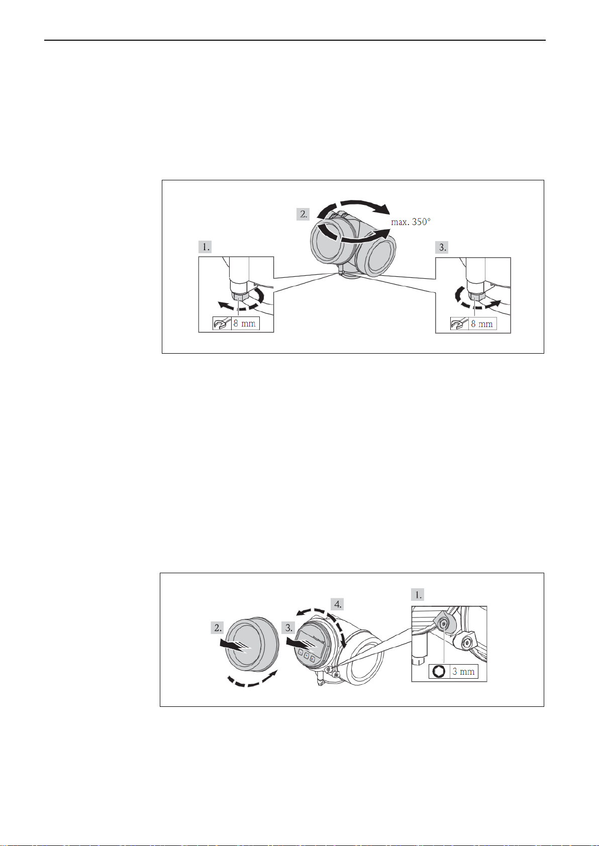
3.6 Transmitter Housing / Display (Mounting/Rotating)
Rotating the Transmitter Housing
The transmitter housing of EF200 can be rotated on the housing support up
to 350° clockwise or counterclockwise to reposition the optional local display
for easy reading.
This is carried out as follows (see Fig. 11):
1. Loosen the securing screw (minimum one turn).
2. Turn the transmitter housing to the desired position.
3. Fasten the securing screw firmly.
Rotating the Display
The display module can be rotated for easy reading in any position (see Fig. 12).
1. Loosen the securing clamp of the electronics compartment cover using a
hex key.
2. Unscrew cover of the electronics compartment from the transmitter
housing.
3. Optional: pull out the display module with a gentle rotational movement.
4. Rotate the display module into the desired position: Max. 8 × 45° in each
direction.
5. Without display module pulled out:
Allow display module to engage at desired position.
6. With display module pulled out:
Feed the cable into the gap between the housing and main electronics
module and plug the display module into the electronics compartment until
it engages.
7. Reverse the removal procedure to reassemble the transmitter.
Figure 12
Rotating the local display
Figure 11
Rotating the
transmitter
housing
172-65639M-01 (EF200) 13 Apr 2018
17
3.7 Protect the Transmitter Against Direct Sunlight
Install the transmitter in a location out of direct sunlight if possible. If the
transmitter is subjected to direct sunlight, even when ambient temperature is
within operational range (80 °C or below), the temperature inside the
transmitter may become higher. Additionally, sunlight may promote
deterioration of the finish and appearance of the unit.
If installation outdoors in an uncovered location in unavoidable, installing the
optional sunshade is recommended. (This is not required when installing
compact version with the transmitter oriented downwards.)
Figure 13
Installing the optional
sunshade

172-65639M-01 (EF200) 13 Apr 2018
18
4. Electrical Connection
4.1 Connecting the Transmitter
Warning!
•Power must be switched off until wiring is completed.
Caution!
•All relevant national installation regulations must be observed.
•The power supply is max. 35 V DC.
Procedure (see Fig. 14)
1. Loosen the securing clamp of the connection compartment cover.
2. Unscrew the connection compartment cover.
3. Push the cable through the cable entry. To ensure tight sealing, do not
remove the sealing ring from the cable entry.
4. Strip the cable and cable ends. In the case of stranded cables, also fit
ferrules.
5. Connect the cable in accordance with the terminal assignment. For HART
communication: when connecting the cable shielding to the ground
terminal, observe the grounding concept of the facility.
6. Firmly tighten the cable glands.
7. Warning!
Housing protection class may be void due to insufficient sealing of the
housing. Reinsert the screw without using any lubricant. The screw threads
on the cover are coated with a dry lubricant.
Reverse the removal procedure to reassemble the transmitter.
To remove a cable from the terminal, use a flat-blade screwdriver to push
the slot between the two terminal holes while simultaneously pulling the
cable end out of the terminal.
Caution!
Figure 14
Procedure for connecting
the transmitter
Warning!
Warning!

172-65639M-01 (EF200) 13 Apr 2018
19
4.2 Wiring Diagrams
EF200 Only, Connecting Power Supply
Frequency (Pulse) Output for an Electronic Counter or PLC
Caution!
The residual voltage of pulse output is 2 V at load current of 2 mA or less,
or 8 V at 10 mA. Make sure to select an electronic counter or PLC
conforming to these specifications or an instrument that can be set to “Low”
level.
Current Output for an Analog Data Receiver
NOTE: Shielded cable recommended for current output.
Power
Supply
+24V
+
–
Electric Counter
or PLC
(Open collector input)
Power
Supply
+24V
+
–
Power
Supply
+24V
+
–
+
–
Data Receiver
(Analog 4 –20 mA
current input)
Figure 15
Power Supply DC24V
Figure 17
Analog current output
connection
Figure 16
Pulse output to electronic
counter or PLC
Caution!
172-65639M-01 (EF200) 13 Apr 2018
20
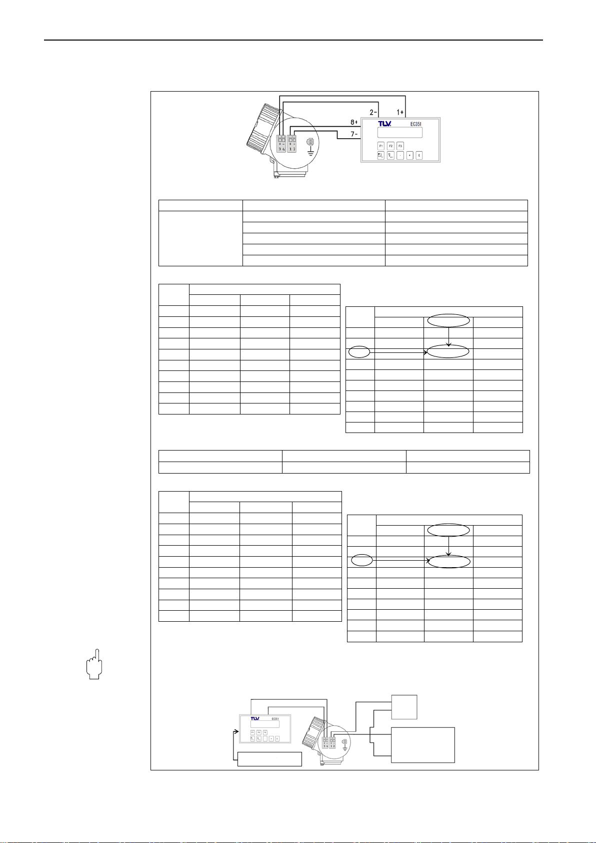
4.3 Connecting to TLV EC351 Flow Computer and Parameter
Settings
EF200 Pulse Output Settings
Submenu
Parameter
Selection
Pulse/
frequency/
switch output
Operating mode
Pulse
Assign pulse output
Volume flow
Volume unit
L (liter)
Value per pulse
See Table A
Pulse width
5 ms
Table A
Size
Value per pulse [dm3/P]
e.g. When connecting a DN 40 EF200F to
EC351, enter a “Value per pulse” of 0.855103
Size
Value per pulse [dm3/P]
EF200W
EF200F
EF200R
15
0.098400
0.068400
–
25
0.448700
0.347799
0.068400
40
1.039101
0.855103
0.347799
50
1.685999
1.425801
0.855103
80
3.793483
3.199488
1.425801
100
6.462871
5.542008
3.199488
150
14.47387
12.60716
5.542008
200
–
24.20136
12.60716
250
–
38.15338
–
300
–
54.73454
–
EF200W
EF200F
EF200R
15
0.098400
0.068400
–
25
0.448700
0.347799
0.068400
40
1.039101
0.855103
0.347799
50
1.685999
1.425801
0.855103
80
3.793483
3.199488
1.425801
100
6.462871
5.542008
3.199488
150
14.47387
12.60716
5.542008
200
–
24.20136
12.60716
250
–
38.15388
–
300
–
54.73454
–
EC351 Flow Rate Input Settings
Function group
Function
Selection
FLOW INPUT
K-FACTOR
See Table B
Table B
Size
K-FACTOR [P/I]
e.g. When connecting a DN 40 EF200F to
EC351, enter a “K-FACTOR” of 1.16945
Size
K-FACTOR [P/I]
EF200W
EF200F
EF200R
15
10.1626
14.61988
–
25
2.22866
2.87522
14.61988
40
0.96237
1.16945
2.87522
50
0.59312
0.70136
1.16945
80
0.26361
0.31255
0.70136
100
0.15473
0.18044
0.31255
150
0.06909
0.07932
0.18044
200
–
0.04132
0.07932
250
–
0.02621
–
300
–
0.01827
–
EF200W
EF200F
EF200R
15
10.1626
14.61988
–
25
2.22866
2.87522
14.61988
40
0.96237
1.16945
2.87522
50
0.59312
0.70136
1.16945
80
0.26361
0.31255
0.70136
100
0.15473
0.18044
0.31255
150
0.06909
0.07932
0.18044
200
–
0.04132
0.07932
250
–
0.02621
–
300
–
0.01827
–
Caution!
An additional sensor is required to convert steam flow rates to mass flow rates when
assigning measurements such as steam dryness fraction calculation to the analog
output (except temperature).
Power
Supply
+24V
+
–
+
–
Data Receiver
(Analog 4 – 20 mA
current input)
-2 1+
Compensation Signal
(Pressure or temperature)
Figure 18
Connecting to TLV flow
computer EC351
Caution!
NOTE: - Assign temperature to the analog output
-
Shielded cable recommended for analog
output
Table of contents
Other TLV Measuring Instrument manuals


Popular Measuring Instrument manuals by other brands

Datakom
Datakom DKM-250 user manual

Gemu
Gemu 1211 Installation, operating and maintenance instructions

Sper scientific
Sper scientific 840080 instruction manual

Apogee Instruments
Apogee Instruments SP-722-SS Operator's manual

Sentinel
Sentinel Hub installation guide

Demtech
Demtech Pro-Tester Double-Pull Operator's manual


TE Connectivity
TE Connectivity Challenger 361 Series Installation and operating instructions

netvox
netvox R718WA2 user manual

Linear Technology
Linear Technology LTC2944 manual

Extech Instruments
Extech Instruments LT300 user guide

Keysight Technologies
Keysight Technologies B2900 Series user guide

Hach
Hach TL2350 Basic user manual