TMG TMG-AHL2 User manual

3300-LB TWIN PAWL BRAKES
CHAIN LEVER HOIST
PRODUCT MANUAL
v2023.01.05
TMG-AHL2
Please read and understand the product manual completely before assembly
Check against the parts list to make sure all parts are received
Wear proper safety goggles or other protective gears while in assembly
Do not return the product to dealer. They are not equipped to handle your requests.
Missing parts or questions on assembly?

IMPORTANT INFORMATION AND WARNINGS......................................................................................................3
IMPORTANT SAFETY INSTRUCTIONS..................................................................................................................3
WARNINGS AND PRECAUTIONS...........................................................................................................................4
SAFETY LABELING................................................................................................................................................5
PRODUCTS SPECIFICATIONS...............................................................................................................................6
PRE INSTALLATION INSTRUCTIONS....................................................................................................................7
OPERATION INSTRUCTIONS.................................................................................................................................8
INSPECTION........................................................................................................................................................10
MAINTENANCE...................................................................................................................................................12
TROUBLESHOOTING...........................................................................................................................................14
PARTS LIST AND EXPLOSION VIEW...................................................................................................................15
Conventions used in this manual
WARNING
This indicates a hazardous situation, which, if not avoided, could result in death or serious injury.
CAUTION
This indicates a hazardous situation, which, if not avoided, could result in minor or moderate injury.
NOTICE
This information is important in proper using of your machine. Failure to follow this instruction could result in damage to your
machine or property.
Additional Information and Potential Changes
We reserve the right to discontinue, change, and improve its products at any time without notice or obligation to the purchaser.
The descriptions and specifications contained in this manual were in effect at printing. Equipment described within this manual
may be optional. Some illustrations may not be applicable to your machine.
TABLE OF CONTENTS

• This product should not be installed, operated, or maintained by any person who has not read all the contents of these
instructions. Failure to read and comply with these instructions, warnings, or limitations noted might result in bodily injury,
death, or property damage.
• Contact the distributor for further explanation if information is not fully understood.
• It is the responsibility of the owner/user to install, test, maintain, and operate these products in accordance with OSHA
regulations, other federal, state, and local regulations, and ANSI standards including:
-ANSI/ASME B30.21- Safety Standard for Lever Hoists
-Other applicable volumes within ANSI/ASME B30
• Only trained and qualified personnel shall operate and maintain this equipment.
• Read, understand and follow the safety information contained in these instructions prior to using this tool. Keep these
instructions for further reference.
• Do not exceed rated capacity.Hooks and handles are designed to bend or stretch when overloading is detected.
• Never use handle extensions (cheaters).
• During operation always ensure a firm footing. Operate the hoist from a location that will be clear of the load at all times.
People must stay clear of load at all times. Never use the hoist to lift, support, or transport people. Never lift loads over or
Near people.
• Before lifting a load,confirm that the lever hoist is in good condition and functioning properly. Inspect the lever hoist regularly.
Never use a lever hoist when malfunction, unusual performance, damage,or extensive wear are found.
• Always keep the load chain well lubricated and protect it from weld spatter and other damaging contaminants. Never allow the
load chain or hooks be used as a ground for welding and never touch them with live welding electrodes.
• Never use the lever hoist with twisted,kinked,damaged or worn load chains.Never attempt to lengthen the load chain.
• Always use proper slings and attachments in the correct manner and confirm that they are seated properly in the hook.
• Also confirm that the safety latch assembly has closed completely and not supporting any part of the load.
• Slacked load chain must be taken up carefully. While checking the balance of the load, lift and lower the load about 4” to test
the brake system before lifting further. Loads must be lifted slowly.
• Never run the load chain out beyond the range of the hoist.
• Never allow your attention to be diverted when operating the hoist and never leave a suspended load unattended.
• Do not allow a load to drop, such as over the edge of a platform, while connected to a chain hoist. The sudden drop, even of a
small distance, can cause a severe momentary overload, seriously damaging the chain hoist and possibly resulting in the loss
of the load. This can occur at loads rated well below the rated capacity.
• Never adjust or repair a chain hoist unless you are qualified to perform hoist maintenance.
• Never modify the chain hoist. Approval from TMG is required for all nonstandard maintenance.
• Use only genuine TMG INDUSTRIAL parts when repairing the chain hoist.
• Never remove or obscure the nameplate on the chain hoist.
• Hoists are rated for use between -40 to +60 ºC, Humidity 100% or below. These are not underwater devices.
IMPORTANT INFORMATION AND WARNING
IMPORTANT SAFETY INSTRUCTIONS

The following warnings and operating practices are intended to avoid unsafe hoisting practices which might lead to personal
injury or property damage.
DO DO NOT
1. DO read the operating and maintenance instructions
2. DO be familiar with hoist operating controls,
procedures, and warnings.
3. DO make sure that the unit is securely attached
to a suitable support before applying load.
4. DO maintain firm footing or be secured when
operating unit.
5. DO make sure that load slings or other approved
sling attachments are properly sized and seated
in the hook saddle.
6. DO make sure the hook safety latches are
closed and not supporting any part of the load.
7. DO make sure load is free to move and will clear
all obstructions.
8. DO take up slack carefully, check load balance,
move the load a few inches, and check load
holding action before continuing.
9. DO make sure all persons stay clear of the
supported load.
10. DO avoid swinging of load or load hook.
11. DO protect load chain from weld spatter or other
damaging contaminants.
12. DO avoid lever “fly-back” by keeping a firm grip on
the lever until operating stroke is complete and the
lever is at rest.
13. DO promptly report any malfunction, unusual
performance, or damage of the unit.
14. DO inspect unit regularly, replace damaged or
worn parts, and keep appropriate records of
maintenance.
15. DO use the recommended TMG INDUSTRIAL parts
when repairing unit.
16. DO apply lubricant to load chain as recommended
by TMG INDUSTRIAL
1. DO NOT lift or pull more than rated load.
2. DO NOT use the hoist load limiting device to measure the load
weight.
3. DO NOT use damaged unit or unit that is not working correctly.
4. DO NOT apply a load unless chain is properly seated in chain
wheel(s) or sprocket(s).
5. DO NOT use with twisted, kinked, damaged or worn chain.
6. DO NOT apply a load if any binding prevents equal loading on all
load supporting chains.
7. DO NOT use load chain as a sling or wrap chain around a load.
8. DO NOT apply the load to the tip of the hook.
9. DO NOT operate except with hand power.
10. DO NOT operate unit when it is restricted from adjusting itself to
form a straight line with the direction of loading.
11. DO NOT operate with any lever extension or cheater bar.
12. DO NOT allow your attention to be diverted from operating the
unit.
13. DO NOT allow more than one operator to pull on chain at
same time.
14. DO NOT operate unit beyond limits of load chain travel.
15. DO NOT attempt to “free-wheel” unit with any load applied.
16. DO NOT use hoist to lift, support or transport people.
17. DO NOT lift loads over people.
18. DO NOT leave a load supported by the unit unattended unless
specific precautions have been taken.
19. DO NOT allow unit to be subjected to sharp contact with other
units,structures, or objects through misuse.
20. DO NOT allow the chain or hook to be used as a ground for
welding.
21. DO NOT allow the chain or hook to be touched by a live
welding electrode.
22. DO NOT remove or obscure the warnings on the unit.
23. DO NOT adjust or repair a unit unless you are qualified to
perform such maintenance.
24. DO NOT attempt to lengthen the load chain or repair damaged
load chain.
25. DO NOT allow loads to drop suddenly while operating this lift.
WARNINGS AND PRECAUTIONS

WARN
INGS TAGS AND LABELS
The warning tags illustrated below are supplied with each hoist shipped from TMG INDUSTRIAL. If the tag is not attached to your
hoist’s no-load side of the load chain, order a tag from your dealer or TMG INDUSTRIAL and install it. Read and follow all
warnings and guidelines attached to this hoist.
1. These general instructions deal with the normal installation, operation, and maintenance situations encountered with the
equipment described herein. The instructions should not be interpreted to anticipate every possible contingency or to
anticipate the final system, crane, or configuration that uses this equipment. For systems using the equipment covered by this
manual, the supplier and owner of the system are responsible for the system’s compliance with all applicable industry
standards, and with all applicable federal, state, and local regulations/codes.
2. Record your hoist’s model, purchasing date and Serial Number on the front cover of this manual for identification and future
reference to avoid referring to the wrong manual for information or instructions on installation, operation, inspection,
maintenance, or parts.
3. Use only TMG INDUSTRIAL authorized replacement parts in the service and maintenance of this hoist
1. It is the responsibility of the owner/user to install, inspect, test, maintain, and operate a hoist in accordance with ANSI/ASME
B30.21, "Safety Standard for Lever Hoists" and OSHA Regulations.
2. If the hoist is installed as part of a total lifting system, such as an overhead crane or monorail, it is also the responsibility of
the owner/user to comply with the applicable ANSI/ASME B30 volume that addresses that type of equipment.
3. It is the responsibility of the owner/user to have all personnel that will install, inspect, test, maintain, and operate a hoist, read
the contents of this manual and applicable portions of ANSI/ASME B30.21, "Safety Standard for Lever Hoists" and OSHA
Regulations.
4. If the hoist owner/user requires additional information, or if any information in the manual is not clear, contact TMG or the
distributor of the hoist. Do not install, inspect, test, maintain, or operate this hoist unless this information is fully understood.
5. A regular schedule of inspection of the hoist in accordance with the requirements of ANSI/ASME B30.21 should be
established, and records maintained.
SAFETY LABELING
NOTICE

PRODUCT SPECIFICATIONS
MODEL
CAPACITY
(Ton)
STD LIFT
(ft.)
CHAIN DIA.
X FALLS
HOOK
OPENING (mm)
DIMENSION
(in.)
SHIP WEIGHT
(lbs)
D
A
B
C
L
H
TMG-AHL2
1-1/2
5
Ø8X 1
36.0
6.93
4.02
6.10
16.34
14.96
26
PRODUCT SPECIFICATIONS

1. PREPARATION FOR USE
• Inspect carefully for any damage that may have occurred during shipping. Check for loose, missing, or damaged parts.
• Lubricate the load chain along the whole length with non-acid, non-corroding machine oil (See Figure 1).
• Examine the load chain to ensure that there are no twists (See Figure 2). 6 ton chain hoists have 2 falls of load chain,
Twists can arise from the bottom hook being turned over through the load chains (See Figure 3). If a twist is found, reverse
capsize the chain to correct.
• Confirm the brake is functioning properly by lifting a test load (10% of rated capacity) a few inches off the ground several
times.
• Confirm that the supporting structure is strong enough to support the full rated capacity of the chain hoist with a generous
factor of safety.
• Be certain all personnel are clear of the load to be lifted and moved. Make sure the load will clear stockpiles, machinery, or
other obstructions when hoisting and traveling the load. Make sure the hoist operation area allows enough room for lever
operation, a clear zone for the operator and other personnel to stand, and allows the frame to swivel freely on the upper hook.
1. Operator requirements
• Read and fully comprehend this entire manual before hoist operation.
Operator must be trained in proper hoist operation and dealing with
potential malfunctions. Should not operate hoist while under influence
of alcohol, medications, or drugs. Should not operate the hoist while
tired or distracted. Should not operate hoist if they have a history of
seizures or other medical issues that may interfere with hoist operation. Should have proper coordination and vision.
2. Prior to operation be sure
• Hoist is clean and properly lubricated. Hoist is in proper working condition and maintenance records are up to date. Brake is
functioning properly. Area of operation is clear of flammable materials.
3. During hoist operation
• Maintain secure footing to prevent slipping and injury while operating. Confirm that hoist unit is attached securely to a
support before operation. Verify hook latches are not supporting any of the load. Do not hold the chain during hoist operation.
Slowly take up the load, verifying it is well supported and balanced before proceeding.
4. Free chain(free-wheeling) operation
Allows the unloaded hook to be quickly moved to the desired position by hand in order to attach the load.
1. Place the selector lever(Part No.5-2) to the Neutral (“N”)position.
2. Pull the load chain to the desired position to attach the load.
3. To disengage the free chain operation, move the selector lever to the (up) or (down) position.
4. Pull the load chain in both directions to assure it is out of free chain mode.
PRE INSTALLATION INSTRUCTIONS
Lubrication
Figure 1
Figure 2
Figure3
Appearance
Of chain that is
NOT Twisted
Appearance
Of chain that is
Twisted
OPERATION INSTRUCTIONS

WARNING
Do not touch the hand wheel while lifting or lowering. Do not operate free chain mode while there is a load on the hoist.
Free-Wheeling will not be possible during the following conditions:
• When the lever hoist is under a load.
• When the guide handle (hand wheel) is in contact with something and not rotating freely.
• When the brake has locked from a large or abrupt load, turn the guide handle (hand wheel) 45 degrees counterclockwise
to unlock the brake.
• When the brake is locked.
• The brake can be unlocked by setting the selector lever to the “DOWN” position and manipulating the operating handle
counterclockwise.
5. Attaching the load
•If there are no twists in the chain, proceed on to attach the lower hook to the load.
•Do not use the chain to wrap around the load.
•The load should be seated in the bowl of the hook and should not bear against the tip of the hook or latch.
•The hook latch should be tightly closed against the hook tip
•Assure that the upper and lower hooks form a straight line and frame is able to swivel.
NOTICE
The lever hoist will automatically change from the free-wheeling condition to the brake locked condition
when a load is attaching.Attaching the load with one of the following two methods:
• Turn the hand wheel(Part No.2) clockwise until the brake locks from the force of the load.
• Pull firmly non-load side of the chain until the brake locks
from the force of the load (See Figure 4, 5). Turn the
selector lever to the “UP” position and hoist or pull by
manipulating the operating handle.
6. Hoisting (Pulling) and lowering (Releasing)
Hoisting (Pulling)
•Set the selector lever to the “UP” position. Take up the slacked load chain by turning the hand wheel clockwise or by free
wheeling (see above 4). Next, Manipulate the operating handle clockwise.
Lowering (Releasing)
•Set the selector lever to the “DOWN” position. Manipulate the operating handle counterclockwise. When there is no load on
the lever hoist, the load chain can be slackened by turning the hand wheel counterclockwise.
WARNING
1. Do not continue to lower the hoist when the end anchor(Part No.39) is against the hoist as damage to the hoist and loss of
load may result.
2. Pull the chain out by hand or turn the hand wheel (Part No.2) counter-clockwise to unhook the load.
Do Not release the load by other means than by cranking by the lever as the brake will remain tight or locked. If this happens,
jerk the lever in the down direction sharply to release the brake
Figure 4
Figure 5

7. Operating precautions
•Keep the load within the rated capacity marked on the lever hoist. An excess load may lead to an accident. The lever hoist is
overloaded when the lever handle is bent or the latch on the load hook will no longer close.
•Before operating, lift and lower the load about 4” (10cm) and test the braking system. Ineffective braking may lead to an
accident.
•Loads must be lifted as slowly as possible. Load swinging and abrupt shocks will impose excessive stress on the lever hoist
and could lead to overloading or brake locking.
•Extreme temperatures will affect the durability of the lever hoist. In subzero temperatures, loads must be lifted and lowered
very slowly and carefully.
•When hooking, the load must be applied squarely to the centre of the hook and the hook must not come loose during operation.
Never use the hook directly on a load (See Figure 6). Lift loads only with applicable clamps or hooks (See Figure 7).
•Mount the top hook for a fixed location. Ensure the fixed suspension point rests on the centre of the hooks saddle and that the
hook’s safety latch is engaged.
Figures 8 through 10 show improper hooking methods, which may cause the hook to elongate or bend. These hooking methods
may also obstruct the load chain and prevent the lever hoist from operating properly. In applications similar these, be sure to
use the correct slings and attachments to ensure safe operation and long life of the lever hoist.
•Never run the chain out too far. When the lever hoist is run out beyond the range of the lift, a dangerous excessive load is
imposed on the load chain, chain safety stop, and bearings.
•The selector lever must be set to the “UP”position when the lever hoist is under a load during hoisting or pulling.
•Lifting a load with two lever hoists is NOT RECOMMENDED. When lifting a load with more than one hoist, always ensure that
both hoists can lift the entire load individually.
•Do not throw or drop the lever hoist from high places. Do not drag the lever hoist during transportation. Doing so may cause
damage that may lead to an accident.
Figure 6
Figure 7
Figure 8
Figure 9
Figure10
Figure11

8. Care after use
•Never leave or store the lever hoist with the brake system locked. Loosen the brake system by operating the lever hoist as if
lowering a load.
•Always service and repair the lever hoist after use. Thoroughly clean the dust or if used in the rain, wipe off the dirt and
moisture. Lubricate all moving parts of the hoist after use, especially the load chain, to prevent rust.
•Inspect the hooks and load chain for bends and any other type of defects. Also check to see if the hooks freely rotate. If any
defect is found, replace the defective component before using the lever hoist again.
1. INSPECTION PRECAUTIONS
• All new, altered or modified equipment should be inspected and tested by personnel trained in the safety, operation and
maintenance of this equipment to ensure safe operation at rated specifications before placing equipment in service.
• Frequent and Periodic inspections should be performed on equipment in regular service.
• Frequent inspections are visual examinations performed by operators or service personnel and include observations made
during routine equipment operation.
• Periodic inspections are thorough inspections conducted by personnel trained in the safety, operation and maintenance of
this equipment.
• ASME B30.21 states inspection intervals depend up the nature of the critical components of the equipment and severity of
usage.
• Deficiencies revealed through inspection or operation must be reported to designated personnel trained in safety, operation
and maintenance of this equipment. Any corrective action must be completed and documented by written report before
placing the equipment in service.
2. RECORDS AND REPORTS
• Inspection records should be maintained for all load bearing equipment requiring periodic inspection.
• Written reports should be made on the condition of the critical parts as a method of documenting periodic inspection.
These reports should be dated, signed by the person who performed the inspection, and kept on file where they are readily
available for review.
3. FREQUENT INSPECTION
• The Manual Lever Hoist should be inspected at the beginning of each shift. Visual inspections should also be conducted
during regular service for any damage or evidence of malfunction which appears between regular inspections.
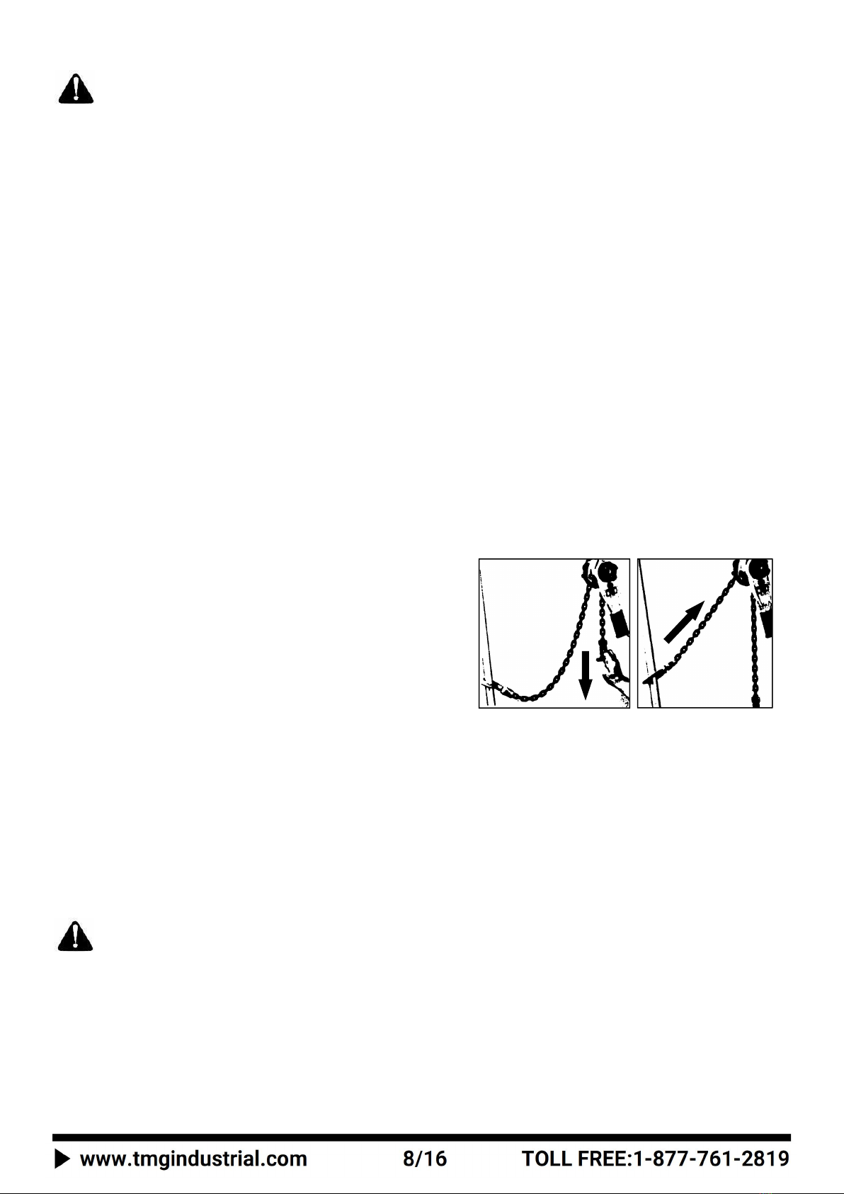
»»OPERATION: Check for visual signs or abnormal noises which could indicate a potential problem. Do not operate a hoist
unless the chain feeds through the hoist and hook block smoothly. If the chain binds, jumps or is excessively noisy, clean
and lubricate the chain. Do not operate the hoist until all problems have been corrected. The bottom hook should stop
moving when the hand chain stops moving.
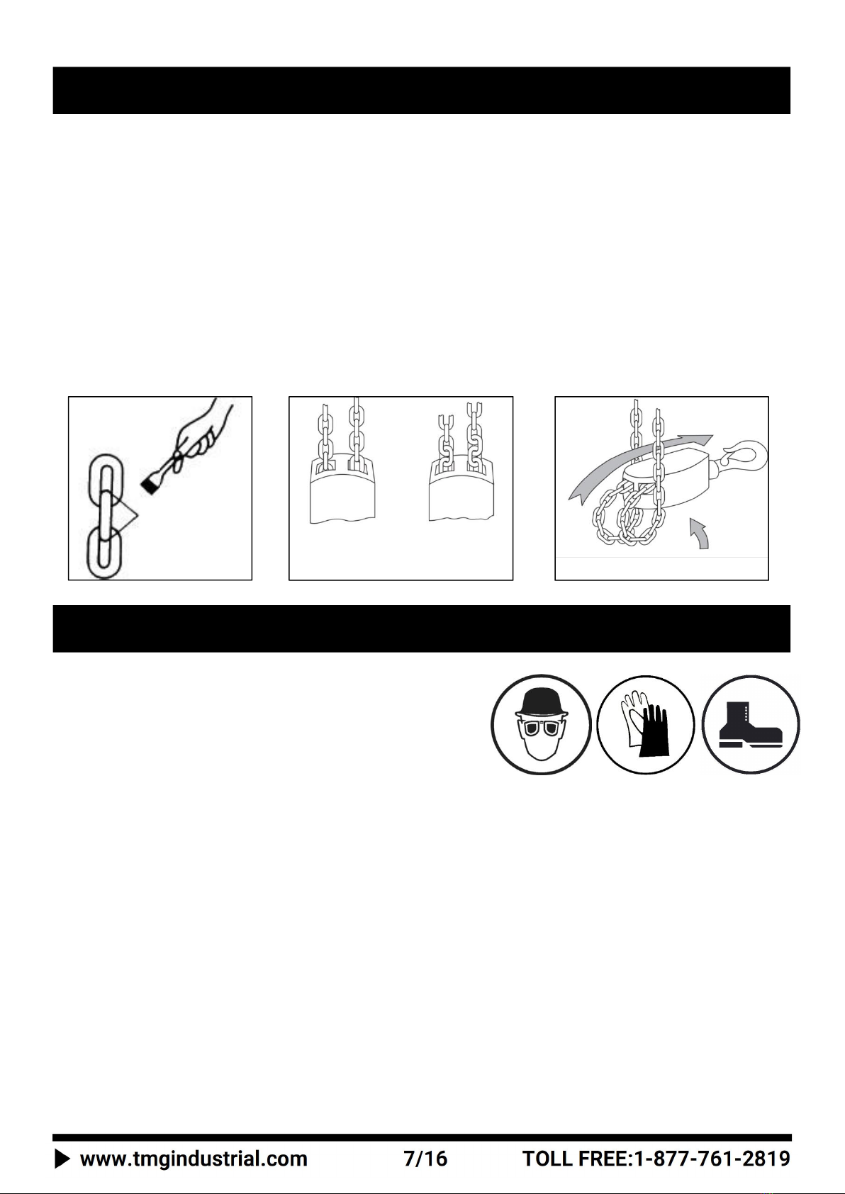
»»HOOKS: Check for wear and damage monthly. This includes: cracks, twists, latch engagement and latch operation (See
Figure 12). Replace hooks that exceed the throat opening discard width. If the hook latch snaps past the tip of the hook, the
hook has been overloaded and must be replaced. Check the hook support bearings for lubrication and damage. Check that
hooks swivel easily and smoothly. Repair or lubricate as needed.
»»HOOK LATCHES: Check operation of hook latches. Replace if broken or missing. Ensure they catch the tip of hook.
»»CHAIN: Examine each link for bending, cracks in weld areas or shoulders, transverse nicks and gouges, weld spatter,
corrosion pits, striation (minute parallel lines) and chain wear, including bearing surfaces between chain links (See Figure 13).
Replace a chain that fails any of these inspections. Check lubrication and lubricate if necessary.
»»LOAD CHAIN REEVING: Make sure welds on standing links are away from the load sheave. Reinstall chain if necessary (See
Figure 14). Make sure chain is not capsized, twisted or kinked (See Figure 2 & 3). Adjust as required.
»» HAND LEVER: Check for cracks, bending and other damage. Replace if necessary.
INSPECTION PROCEDURES

4. PERIODIC INSPECTION
• According to ASME B30.21, frequency of periodic inspection depends on the severity of usage.
• Disassembly may be required for HEAVY or SEVERE usage. Any deficiencies must be corrected before hoist is returned to
service. Keep records of periodic inspections to provide a basis for continuing evaluation. Inspect all items in ‘Frequent
Inspection’. Also inspect the following:
»»Chain for excessive wear or stretch.
»»Worn, cracked or distorted parts such as hook blocks, top hooks, chain guide, stripper, loose end pin, shafts, gears, hook
collar and bearings.
»»Inspect for wear on the top of the pawl, teeth of the ratchet and pockets of the lift wheel and hand wheel. Loose or missing
bolts, nuts, pins or rivets.
»»Inspect brake components for worn, glazed or contaminated friction discs and scoring of the hand wheel hub, ratchet, and
friction hub.
»»Corroded, stretched or broken pawl spring.
»»Free movement of the pawl on the pawl stud.
»»Hook inspections using dye penetrant, magnetic particle or other suitable crack-detecting inspections should be
performed at least once per year, if external conditions indicate possible unusual usage.
»» Ensure chain stopper is installed in the last link of the anchor end of the load chain. Replace if missing.
5. HOISTS NOT IN REGULAR USE
• A hoist that has been idle for a period of one month or more should be given a Frequent Inspection before use.
• A hoist that has been idle for a period longer than one year should be given a Periodic Inspection before use.
• Standby hoists should be inspected at least semiannually in accordance with the Frequent Inspection. In abnormal operating
conditions this inspection should be completed at shorter intervals.
NORMAL
HEAVY
SEVERE
Yearly
Semiannually
Quarterly
Figure 12
Normal
USE
Twisted
DO NOT USE
Diameter
Figure 13
Welded Area
Wear
In these
areas
Standing
link
Load
sheave
Figure14
Load
chain
Chain
weld

• The lever hoist is designed and manufactured to withstand heavy duty material handling operations, but wear and damage are
unavoidable after a extended use in less than ideal environments.
• Never leave the hoist in a damp environment or damp weather such as rain. Always store the hoist in a dry, well ventilated area.
• Proper lubrication will help lengthen the life of the chain hoist. Before storing, check to see if the hoist is well lubricated. Be
especially sure that the moving parts, such as gears and bearings, are well lubricated.
• Load chain and hooks
Note: The load chains and hooks are precisely heat-treated.
Never weld or heat-treat the load chain.
1. Lubrication
Proper lubrication with machine oil is necessary to increase the life of the chain. Lubrication should be done based on usage and
on a regular basis. It may be necessary on a weekly basis for heavy use or monthly if used less often.
• Clean the chain with an acid free cleaning solution to remove debris.
• Apply oil to chain focusing on bearing surfaces such as interlink areas.
• Do not apply oil to braking surfaces.
• Gears and shafts run on roller bearings and do not require lubrication.
2. Disassembly to Replace Load Sheave or Stripper
1. Remove the chain
2. Remove the lock nut (1), bolts(3), plain washer (4), hand wheel (2), lever handle (5), overload/brake cover assembly cover
assembly (13), female thread grip (10), friction disc (16), ratchet disc (17), free spring (15),and brake seat (18).
3. From the gear side remove the gear cover assembly (32), disk gear assembly (28), and drive shaft (29).Then remove the snap
ring (31) , spline gear (30), and gear side plate assembly (27). Slide the load sheave out of the gear side plate. Now the
stripper can also be removed (26).
3. Assembly
Before reassembly check each part for damage, corrosion, or excessive wear. Replace parts as necessary. Re-assemble the hoist
in reverse order to the disassembly steps listed above.Once assembled the chain can be installed and before use the unit should
be tested for proper function.
4. Storage of Hoist
Store the hoist in a clean dry area.
Maintain proper lubrication of the hoist while it is being stored.
If the hoist is malfunctioning clearly mark it before placing it in storage.
5. Outdoor Hoist Usage
Store hoist indoors when not in use.
Frequently inspect the hoist for signs of corrosion due to environmental factors.
MAINTENANCE INSTRUCTION

6. Load Chain
Load chains worn-out or elongated beyond the permissible dimensions must be replaced at once. To examine, clean the chain
with an acid-free solvent and, using a caliper style gauge, measure the inside length of 5 links of chain under light tension.
Replace the entire load chain immediately if even one link of the load chain is extensively worn-out, elongated or damaged.
5 LINKS
Load Chain Dimensions
7. Hooks
TMG material handling hooks are designed to bend slightly when overloaded. If the hook opening is elongated beyond the
permissible dimension (10% greater than standard), the hook is dangerously deformed and must be replaced at once. No
deformation of the hook will arise when the chain hoist is used and maintained properly.
HOOK DIMENSIONS
* Limit C size is 10%wider than the standard hook opening. The safety latch will not catch the hook tip once the hook is stretched
beyond this point.
CAPACITY( Tons)
DIAMETER(Ø mm
)
STANDARD*(Ø mm)
LIMIT*(mm)
1-1/2
8
119.8
123.4
3
10
149.6
154.1
6
10
149.6
154.1
CAPACITY
(TONS)
STANDARD C SIZE (mm)
MAX C SIZE* (mm)
1-1/2
36.0
39.6
3
46.0
50.6
6
46.0
50.6

ONDITION
PROBABLE CAUSE
HOW TO REPAIR
Hoist will not lift load
1. Excess slack in load chain.
2. Hoist is overloaded.
3. Hoist is in NEUTRAL (N) mode
1. Pull down on load chain while ratcheting
until slack is removed and hoist begins
lifting load
2. Reduce load to within rated capacity
3. Ensure selector lever is in UP position.
Slip caused by ineffective braking
1. Worn-out friction discs.
2 . Excessive oil on the braking
surface.
3 . Incorrect assembly of the braking
system.
1. Replace with new friction discs.
2 . Disassemble and clean.
3. Assemble correctly.
Load dropped while lowering
1. Damaged friction discs.
2. Foreign matters in the braking
system.
1. Replace with new friction discs.
2. Disassemble and clean.
Load chain binds
1. Damaged load chain, pinion shaft,
gears or sheaves.
2. Load chain not installed properly
(twisted, kinked or ‘capsized’).
1. Disassemble and inspect components.
2. Inspect and adjust or repair.
Jammed operating handle
1. Over-tightening of the brake.
1. Operate lever hoist as if lowering a load.
Noises during hoisting and lowering
operation
1. Wear or deformation of the load
chain and load sheave.
1. Replace with new parts.
Operating handle becomes difficult to
operate during lifting or lowering
operation
1. Over-hoisting or over-lowering.
2. Twist in the load chain causing it to
get caught between load sheave
and load chain guide.
1. Operate the hoist in opposite direction.
2. Operate the hoist in the opposite direction
and remove the twist from the load chain.
Load will not go down
1. The hoist was left under load for
extended period.
2 . Over tightened brake.
3 . Shock loaded during operation.
4. Brake rusted tight.
1. For non-overload protection chain hoists,
pulling harder on the chain may loosen
brake.
2-4. If load cannot be moved, use another
lifting device to remove the load from the
affected hoist and replace brake
components and perform hoist
maintenance.
TROUBLE SHOOTING PROCEDURES

Assembly Diagram
PARTS LIST AND EXPLOSIVE VIEW
1
2
3
4
9
5
42
41
43
40
44
6
7
8
17
16
15
11
12
14
11
13
10
21
18
20
19
22
24
25
23
24
34
26
27
36
30
39
29
38
28
37
35
32
11
28
31
33
5-1
5-2
5-3
5-4
5-5
5-6
34-3
38-1
38-2
34-5
38-3
34-4
34-2
28-2
32-2
28-1
27-2
27-3
32-3
22-2
32-1
34-1
5-3
27-2
27-1
13-1
22-1
13-2
34-3
34-6
34-4
34-5
34-2
34-7

Parts List
PART NO.
DESCRIPTION
QTY
PART NO.
DESCRIPTION
QTY
1
Hex nut of hand wheel cover M6
1
27
Side plate assembly B
1
2
Hand wheel
1
27-1
Right side plate
1
3
Hexagon bolts M6x12
2
27-2
Steel ring
4
4
Plain washer Ø6
2
27-3
Support pin
4
5
Lever handle assembly
1
28
Disc gear assembly
2
5-1
Lever handle
1
28-1
Gear 1st
2
5-2
Selector
1
28-2
Gear 2nd
2
5-3
Washer of lever handle
2
29
Drive shaft
1
5-4
Pin of selector
1
30
Splined gear
1
5-5
Bolts
2
31
Snap ring
1
5-6
Spring seat
1
32
Gear cover assembly
1
6
Change over pawl
1
32-1
Gear cover
1
7
Shaft of change over pawl
1
32-2
Steel ring
1
8
Spring of shaft
1
32-3
Rivet of gear cover Ø2.5x6
2
9
Locking plate
1
33
Top hook shaft
1
10
Female thread grip
1
34
Top hook assembly
1
11
Hex nut of brake cover M8
8
34-1
Top hook
1
12
Brake cover
1
34-2
Pin of safety latch
2
13
Overload/brake cover assembly
1
34-3
Hex nut of safety latch M4
2
13-1
Inner cover
1
34-4
Spring of safety latch of top hook
2
13-2
Bolt
2
34-5
Safety latch
2
14
Hex nut of inner cover M6
1
34-6
Rivet of bottom hook’s housing
Ø5x20
2
15
Spring of pinion shaft
1
34-7
Top hook’s housing
2
16
Friction disc
2
35
Load chain
1
17
Ratchet disc
1
36
Suspension pin of bottom hook
1
18
Brake seat
1
37
Hex nut of suspension pin M6
1
19
Washer of pawl-A type
2
38
Bottom hook assembly
1
20
Pawl
2
38-1
Bottom hook
1
21
Spring of pawl
2
38-2
Bottom hook’s housing
2
22
Side plate assembly A
1
38-3
Rivet of bottom hook Ø5-20
4
22-1
Left side plate
1
39
End anchor
1
22-2
Pin of pawl
2
40
Hand grip
1
23
Load chain cover
1
41
Lock nut M3.5
1
24
Needle bearing
2
42
Screw of hand sleeve M3.5x6
1
25
Load sprocket
1
43
Nameplate
1
26
Stripper
1
44
Rivet of nameplate Ø2.5x4
6
Table of contents
Other TMG Chain Hoist manuals
Popular Chain Hoist manuals by other brands

WilTec
WilTec 30154 Operation manual

Atex
Atex Yalelift 360 Operating and maintenance instruction

Ingersoll-Rand
Ingersoll-Rand MLK Series Product Maintenance Information

Planeta
Planeta WICHTEL user manual

Kill Shot
Kill Shot Tree-Hoist quick start guide

HADEF
HADEF 24/12 Installation, operating, & maintenance instructions

Chicago Electric
Chicago Electric 02954 Set up and operating instructions

CarlStahl
CarlStahl CondorLift CLLH0008F user manual

J. D. NEUHAUS
J. D. NEUHAUS PROFI 3 Ti Customer's operating and assembly instructions

HADEF
HADEF 25/13 Installation, operating and maintenance instructions

aci
aci LH Series Operation manual

Hubbell
Hubbell CHANCE 3011S Operating and service instructions