Pacific Hoists U-MEGA Series User manual

Pacific Motorized Trolley
U-MEGA Series
OPERATION MANUAL
&
PARTS LIST
Model
PET050S
PET100S
PET200S
Copyright © 2023 by Pacific Hoists Pty Ltd. No portion of this manual is to be reproduced
without written consent from. Specifications subject to change without notice.

1
SAFETY-IMPORTANT
The use of any hoist and trolley presents some
risk of personal injury or property damage.
That risk is greatly increased if proper instructions
and warnings are not followed. Before using this
hoist, each user should become thoroughly
familiar with all warnings, instructions and
recommendations herein.
THIS SYMBOL POINTS OUT IMPORTANT SAFETY
INSTRUCTIONS WHICH IF NOT FOLLOWED COULD
ENDANGER THE PERSONAL SAFETY AND/OR
PROPERTY OF YOURSELF AND OTHERS. READ AND
FOLLOW ALL INSTRUCTIONS IN THIS MANUAL AND ANY
PROVIDED WITH THE EQUIPMENT BEFORE ATTEMPTING
TO OPERATE YOUR " Pacific " MOTORIZED TROLLEY.

2
CONTENTS
SAFETY-IMPORTANT ……………………………………………………
………………
1
I. Foreword ………………………………………………………………… ………………
…
3
II. Operating and Safety Procedures ………………………………
…………………
4
III. General Information ……………………………………………………
…………………
5
IV. Installation
1.Unpacking Information …………………………………………………………
…
6
2.Trolley to Beam ……………………………………………………………………
…
6
3.Motorized Trolley …………………………………
………………………………
7
4.Hoist with motorized Trolley …………………………
……………………………
8
5.Electric Installation ……………………………………
………………………………
8
6.Test Running ………………………………………………
……………………………
9
V. Inspection ………………………………………………………………………………… 11
VI. Maintenance
………………………………………………………………………………
11
VII. Troubleshooting
…………………………………………………………………………
12
VIII. Parts List
1. Trolley Exploded view ………………………………………
…………………………
14
2. Motor Assembly …………………………………………
…………………………
17
3. Electric Explosion ………………………………………………………
………………
19
IX. CE Certificate of Conformity ……………………
………………………………………
20

3
I. FOREWORD
This manual contains important information to help you properly install, operate and maintain
the motor driven trolley for maximum performance, economy and safety.
Please study its contents thoroughly before putting the trolley into operation.
By practicing correct operation procedures and by carrying out the recommended preventative
maintenance suggestions, you will be assured of dependable service.
In order to help us to supply correct spare parts quickly, please always specify:
1).Trolley Model, 2). Serial Number and 3). Part Number, as well as the description.
We trust that you will find this " Pacific " trolley satisfies your requirements.
Should you have any queries, please contact:
Pacific Hoists Australia
24 Foundry Road
Seven Hills NSW 2147
P | +61 2 8825 6900
E | sales@pacifichoists.com.au
W | www.pacifichoists.com.au
Pacific Hoists New Zealand
11 Druces Road
Wiri Auckland NZ 2104
P | +64 9 263 5566
E | sales@pacifichoists.co.nz
W | www.pacifichoists.com.au

4
II. OPERATING AND SAFETY PROCEDURES
The following are operating and safety procedures for safe operation of the Pacific motor driven
trolley. Taking precedence over and specific rules listed here, however is the most importance
rule of all. A few minutes spent reading these rules can make an operator aware of dangerous
practices to avoid and precautions to take for his own safety and others.
1. Immediately after installation, operate trolley with safe working load over the entire length
of runway or monorail system to be sure that all adjustments and operations are
satisfactory.
2. Rail stops must be installed for all trolleys operating on open end beams. These stops must
be positioned such that impact forces are absorbed by trolley side frames only.
3. When preparing to lift a load, be sure that the attachments to the hook are firmly seated in
hook saddle. Avoid off center loading on the point of hook.
4. When lifting, raise the load only enough to clear the floor or support and check to be sure
that the attachments to hook and load are firmly seated. Continue lift only after you are
assured the load is free of all obstructions.
5. When applying a load, it should be directly under the trolley. Avoid off center loading of
any kind.
6. Take up a slack load chain carefully and start lifting load slowly to avoid shock and jerking
of hoist load chain. If there is any evidence of overloading, immediately lower the load and
remove the excess load.
7. Do not allow the load to swing or twist while hoisting.
8. Anticipate the stopping point and allow trolley to coast to smooth stop. Reversing or
plugging to stop trolley causes overheating of motor and swaying of load.
9. Do not load trolley beyond the rated capacity. Overload can cause immediate failure of
load carrying parts of cause damage resulting in future failure at less than rated capacity.
10. Do not use this or any other overhead materials handling equipment for lifting or
transporting people.
11. Stand clear of all loads and avoid moving a load over the heads of other people. Warn
people of your intention to move a load in their area.
12. Do not leave the load suspended in the air unattached.

5
13. Do not wrap the load chain around the load and hook into itself as a choker chain.
Doing this will result in the follow:
(a) Operation of the upper limit switch is bypassed and the load could hit the hoist.
(b) The loss of the swivel effect of the hook which could mean twisted chain and a
jammed lift wheel.
(c) The chain could be damaged at the hook.
14. Permit only qualified personnel to operate the unit.
III. GENERAL INFORMATION
The Pacific motorized trolleys are designed for use with the Pacific Electric Chain Hoists. The
trolleys are available in the following capacities: 0.5-Ton~2-Ton, These trolleys are similar
except for the size of the load carrying members.
The trolleys have rugged steel side plates with anti-drop fins, steel wheel axles, steel suspension
bolts, construction steel load plate seated in middle of two suspension bolts for top hook of
hoist to hook on. The hot forged travelling wheels machine to suit both I-beam and flat beam.
Hardened steel gears are attached to two trackwheels and driven by a hardened steel pinion.
The pinion is driven by planetary gear reducer in high quality grease. A weather proof motor
drive the gear reducer.
The electric housing contains a reversing contactor and a terminal boards. The transformer will
be an option depending on the user's need. The 1-phase motor is always equipped with a
magnetic brake over the end of driven motor. Above the housing bottom, there three holes,
one for cord from hoist, another for control cord from hoist, the third one for trolley motor cord,
it will serve as an option for equipped with the Push-Bottom-Station cord for the trolley. In
addition, there are two option holes on each side of the housing, motor power cord on the right,
and an optional hole for the power cord to trolley on the left. All five holes are equipped with
cable gland for IP-55 protection optionally. Please refer to Illust: 1 on page 9.

6
IV. INSTALLATION
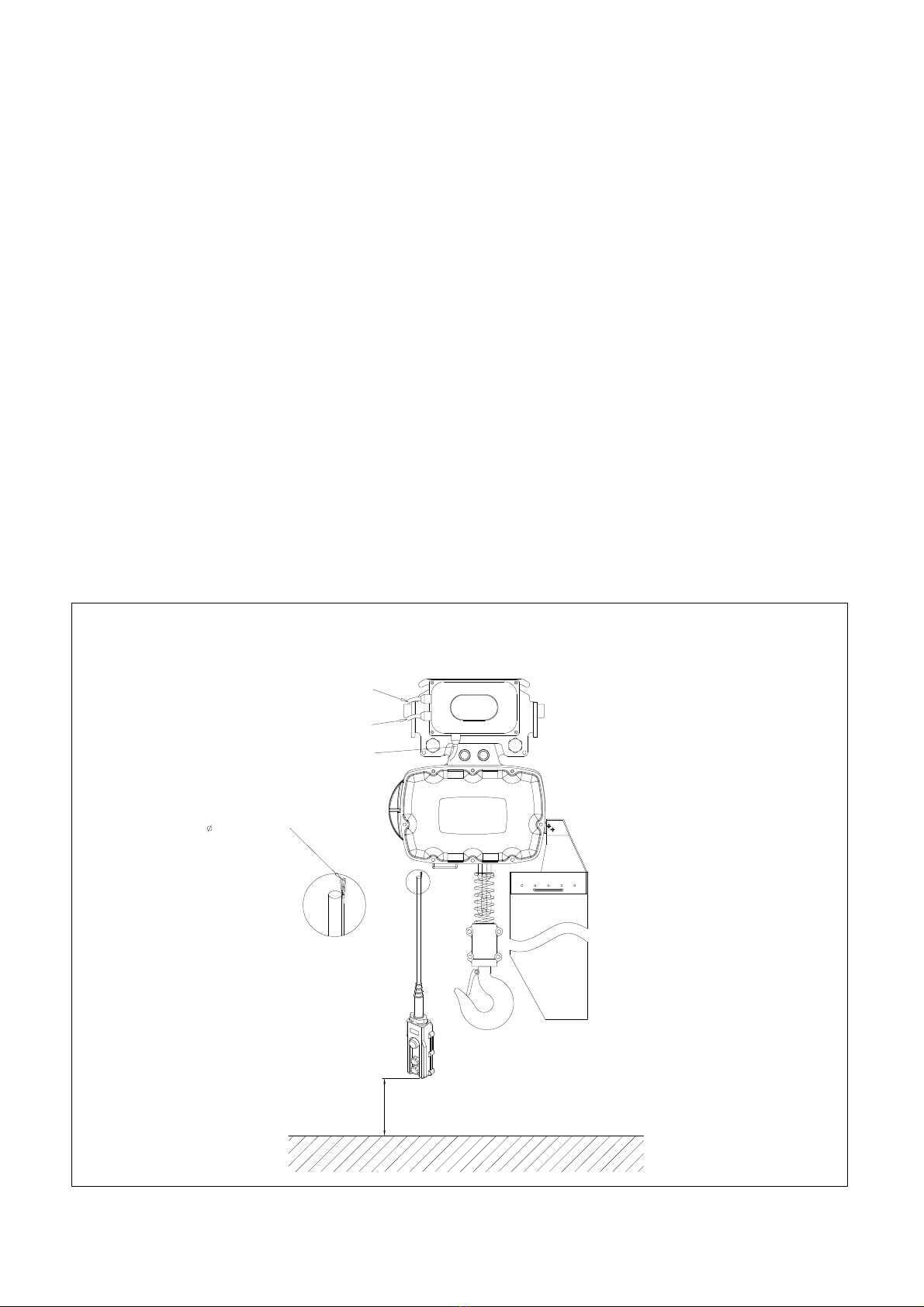
1. UNPACKING INFORMATION
After removing the trolley from the shipping carton/crate, carefully inspect the external
condition of the cord, electric housing, gear reducer, motor for damage that may have
occurred during shipment and handling. Check to make sure all parts are furnished. i.e. trolley
side frame with electric housing, side frame with reducing gear motor, position tube, spacer
washer, stay-bolts, nuts and load plate for hoist top hook. Also, before attempting to install
the trolley, make sure that the power supply indicated on the labels attached to the motor
housing is the same as the power supply on which the unit is to operate.
Generally, the hoist and trolley are packed separately. Except when the order indicates the
requirement of 4-way control for the hoist with trolley, then the hoist will be packed with
trolley together in one wooden crate.
2. TROLLEY TO BEAM
It is recommended that the trolley be mounted on the beam prior to attaching the hoist to
the trolley. Before attempting to mount the trolley on the beam, measure the actual width of
the beam flange on which the trolley is to operate. Using this measurement determine the
arrangement of spacer washers between the two trolley side frames. First loosely assemble
the side frames, position tubes, spacer washers and nuts on the stay bolts.
For all trolley suspended hoist rail stops must be installed at each end of
the rail. Failure to install rail stops will allow the hoist and trolley to fall off
the end of the rail and thus cause an accident that may result in injury
and/or property damage. The stops must be positioned as to not exert
impact force on the hoist frame or trolley wheels. They must contact the
ends of the trolley side frames.
The trolley and beam should be inspected periodically to assure their
continued operations. Operating a malfunctioning trolley and/or operation
the trolley on a beam with an excessively worn flange may allow the trolley
to fall from the beam causing an accident that may result in injury and/or
property damage.

7
Due to the variations in beam flange widths, it is suggested that the beam flange width be
measured to determine the exact distribution of spacer washers. The distance between
trackwheel flanges should be 3-5 mm greater than the beam flange width for straight runway
beams, and 5-7 mm greater than the beam flange width if runway includes sharp curves.
Now install the trolley on the beam by sliding one side frame out far enough to allow the
trackwheels to clear beam flange. Lift the trolley up so that the trackwheels are riding on the
beam and draw the side frames together and tighten the nuts snugly.
3. MOTORIZED TROLLEY
Model
Dimensions(mm) Speed
(m/min)
Motor
(kw)
N.W.
(kg)
Min radius
of
carve(m)
A B C D E F G H L J N K
PET050S 385 125 280 180 75~
125 216 126 95.5 200 52 39 7/8"-9UNC
(Ø22.2) 10 0.18
4P 45 1.3
PET100S 385 114 280 180 75~
125 220 126 120 210 67 39 1"-8UNC
(Ø25.4) 10 0.18
4P 45 1.3
PET200S 395 125 285 185 100~
150 236 159 120 230 75 36
1
1/4"-7UNC
(Ø31.8)
10 0.18
4P 50 1.7

8
4. HOIST WITH MOTORIZED TROLLEY
Model DWG. Dimensions(mm)
A B C D E H
PEH050S+PET050S I 385 126 280 180 75~125 500
PEH100S+PET100S I 385 126 280 180 75~125 550
PEH200S+PET200S Ⅱ 395 159 285 185 100~150 625
5. ELECTRICAL INSTALLATION
The trolley electrical connection must be completed as shown in Illust.1, the Hoist & Trolley
General Arrangement. Generally, the electric housing is provided with three holes in the bottom,
one for trolley motor cord, the second one for trolley power cord from hoist and the third one
for control cord from hoist. Moreover, the optional five holes design for independent usage of
trolley are also available, please refer to the Illus.1. There are two holes on each side of the
housing, on the left is the power cord for trolley, on the right is for the trolley motor cord.
For the details of wiring connection, please refer to the wiring diagrams.
Hoist with trolley wiring diagram shown example as follows:
F2300078310101 is 1 phases model, Please refer to page 10.
For special unit, please see wiring diagram supplied with unit.
Power should be disconnected when making or changing connections, also proper
grounding should be accomplished.

9
Warranty Details:
1. Warranty Period : One year for Mechanical Spare Parts after purchase the product.
2. Non-Warranty Scope:
a. Electrical Spare Parts (ex. Contactor, Pendant, Phase Error Relay, etc.)
b. Expense Spare Parts (ex. Chain Bucket, Brake Lining, etc.)
c. Damage caused by unsuitable operation.
(galvanize plant, chemical plant, and dye-works etc.)
d. Damage caused by operating on the wrong electric voltage.
e. Damage caused by user emending the product.
f. Damage caused by natural disaster.
3. Warranty Scope shall be permitted by Cheng Day Machinery and Within One Year of
damaged Mechanical Spare Parts Repair and Replacement.
(circumstance stated in detail No. 2 are not included.)
6. TEST RUNNING
After trolley to beam, hoist hook to trolley and wiring connection completed, operate the
trolley forward and backward over a short distance. Then you can operate the trolley over the
entire length of runway or monorail system to be sure that all adjustment and operations are
satisfactory.
TO TROLLEY
MOTOR
N/A
CONTROL&POWER
FROM(TO)HOIST
1m
3 STOP SLEEVE
GROUND
NOTE:IN(xxxx)MEANS OPTIONAL OF
ELECTRICAL CONNECTION
HOIST & TROLLEY GENERAL ARRANGEMENT
Illust.1

10
SF23000783-10101
TB:PT 2,5-QUATTRO*8
KM1 KM2
1
2
3
4
1
2
5
6
M
1~
2
3TROLLEY
5
6
3
4
KM2
KM1
KM1
KM2
MOTOR

11
V. INSPECTION
To maintain continuous and satisfactory operation, a regular periodic inspection procedure
must be initiated so that worn or damaged parts can be replaced before they become unsafe.
The frequency of inspection must be determined by the individual application.
The following list gives an inspection procedure for normal usage under normal conditions.
When the unit is subjected to heavy usage or duty, moist or other adverse atmospheric
conditions, shorter time periods must be assigned. Inspection must be made of all parts for
unusual wear, corrosion or damage in addition to those specifically mentioned in the
succeeding list.
It is suggested that the unit be inspected monthly for wear damage and corrosion effects to all
parts with particular attention to the following:
1. Tightness of all fasteners.
2. Contactor and control station for burnt or pitted contacts and loose or corroded terminals.
3. Cables and leads for broken wires, loose or corroded terminals and damaged insulation.
4. Terminal board for loose or corroded connections.
5. Trackwheels for wear of tread, flange and bearings.
6. Gear portion of trackwheel and pinion for wear.
7. Check the wear of top hook to load plate in trolley.
8. Collector or power supply system for damage, wear corrosion and proper operation.
VI. MAINTENANCE
The following three steps are recommended for maintenance:
1. Once a month lubricate track wheel gear and pinion with grease or graphite grease.
2. Motor reducing gearbox uses planetary gear lubricated with cosmo No. 3 grease (Equivalent
to: Shell Unedo 3, Exxon Eastan 3, Mobil Cup Grease 3) for good maintenance. It is highly
recommended that the motor gearbox grease should be changed after 100 hours of
operation, then every 6 months or 2500 hours of normal service. Whichever comes first, the
grease needs to be changed as well.
3. The motor brake should be changed & be checked periodically for wear of brake lining and
disc. The gap between brake lining & disc can be adjusted by the brake adjusting hex. bolts
over the end of motor.

12
VII. TROUBLE SHOOTING
Please refer to table 1 on page 13.
VIII. PARTS LIST (BOM)
1. Motorized Trolley Exploded ......................................................................................... P.14~P.16
2. Motor Assembly .................................................................................................. P.17~P.18
3. Electric Explosion .............................................................................................. P.19~P.19

13
Table 1. Troubleshooting and Remedial Action
IF CAUSE MAY BE REMEDY
1.Trolley does not
operate in either
direction.
2.Trolley operates
in one direction
only.
3.Trolley operates
sluggishly
4.Motor
overheats
a) Power failure at trolley
b) Phase error
(Single phasing)
c) Turn on control circuit
d) Wrong voltage or
frequency
e) Low voltage
f) Excessive load
a) Turn on control circuit
a) Excessive load
b) Low Voltage
c) Worn or dirty rail
a) Excessive load
b) Low voltage
c) Extreme external
heating
d) Frequent starting or
reversing
e) Phase error
Main line or branch circuit switch power on,
branch line fuse blown or circuit breaker
tripped.
Power off, replace or reset.
Check for grounded or connect supply lines or
current collectors.
Power on, grounded or connected one line of
supply system, collectors, trolley wiring,
reversing contactor, motor leads or windings.
Check for electrical continuity.
Power on or shorted windings in transformer or
reversing contactor coil, loosen connection or
broken wire in circuit, mechanical binding in
contactor, control station switch contacts not
making. Check continuity and repair or replace
defective parts.
The voltage and frequency must be the same as
shown on trolley control box.
Control power supply deviates from standard
not to exceed ±10% to prevent abnormal
operation or damage to the motor.
Prevent frequently loading rated load of trolley.
As item 1. c)
As item 1. f)
As item 1. e)
Clean rails, inspect for worn spots.
As item 1. f)
As item 1. e)
Above an ambient temperature of 40℃., the
frequency of trolley operation must be limited
to avoid overheating of motor. Special
provision should be made to ventilate the
space or shield the trolley from heat radiation.
Excessive inching, jogging or plugging should
be avoided since this type of operation will
drastically shorten the life of motor and
contactor.
As item 1. e)

14
TROLLEY FRAME EXPLOSION
6
13 12 11
12
435
7
8
9
10
17
15
3
16
14

15
TROLLEY ASSEMBLY
NO. PARTS
CODE DESCRIPION Q’TY REQ’D EACH UNIT
PET050S PET100S PET200S
1
210311N
Electric Frame Ass’y
1
217577N 1
217579N 1
2 400922 Retaining Ring <R-40> 4 4 -
3407850 Bearing <6203 ZZ> 4 4
407715 Bearing <6205 ZZ> 8
4203128 Plain Wheel <Ø88×28L> 2 2
203510 Plain Wheel <Ø119×49L> 2
5404184 Retaining Ring <S-17> 4 4
400192 Retaining Ring <S-25> 4
6203110 Gear Wheel <M2×46T×33L> 2 2
210323 Gear Wheel < Ø130×54L> 2
7
210312N
Motor Frame Ass’y
1
217576N 1
217578N 1
8
408366 Stay Bolt <7/8
”
×9UNC×265L>Beam 75~125 2
408367 Stay Bolt <7/8
”
×9UNC×340L>Beam 125~210 2
408368 Stay Bolt <7/8
”
×9UNC×440L>Beam 210~310 2
408411 Stay Bolt <1
”
×8UNC×265L>Beam 75~125 2
408412 Stay Bolt <1
”
×8UNC×355L>Beam 125~210 2
408370 Stay Bolt <1
”
×8UNC×450L>Beam 210~310 2
400394 Stay Bolt <1 1/4”×7UNC×335L>Beam 100~150 2
400410 Stay Bolt <1 1/4”×7UNC×395L>Beam 150~225 2
408307 Stay Bolt <1 1/4”×7UNC×480L>Beam 225~310 2
9
203151 Position Tube <Ø34ר24×56L> 4
217565 Position Tube <Ø38ר28×56L> 4
217566 Position Tube <Ø48ר34×69L> 4
10
210314N
Load Bracket
1
217569N 1
217570N 1

16
TROLLEY ASSEMBLY
NO. PARTS
CODE DESCRIPION Q’TY REQ’D EACH UNIT
PET050S PET100S PET200S
11
203221
Spacer Washer <
Ø
40×
Ø
24×1/8
”
>Beam 75~125
32
203221
Spacer Washer <
Ø
40×
Ø
24×1/8
”
>Beam 125~210
84
203221
Spacer Washer <
Ø
40×
Ø
24×1/8
”
>Beam 210~310
148
203222
Spacer Washer <
Ø
46×
Ø
27×1/8
”
>Beam 75~125
32
203222
Spacer Washer <
Ø
46×
Ø
27×1/8
”
>Beam 125~210
84
203222
Spacer Washer <
Ø
46×
Ø
27×1/8
”
>Beam 210~310
148
203223 Spacer Washer < Ø54ר34×1/8”>Beam 100~150 32
203223 Spacer Washer < Ø54ר34×1/8”>Beam 150~225 80
203223 Spacer Washer < Ø54ר34×1/8”>Beam 225~310 132
12
400102 Spring Washer <7/8"> 4
400103 Spring Washer <1”> 4
400105 Spring Washer <1 1/4”> 4
13
400070 Hex. Nut <7/8"×9UNC> 4
400071 Hex. Nut <1”×8UNC> 4
400072 Hex. Nut <1 1/4”×7UNC> 4
14 206185 Bumper 4 4 4
15 400857 Spring Washer <M10> 4 4 4
16 408364 Hex. Head Bolt <M10×1.5×20L> 4 4 4
17 107895 Motor Ass’y <0.18KW 1 Phase 50HZ 240V 4P> 11 1

17
16
15
11
10 14
13
TROLLEY MOTOR EXPLOSION
1
5
2
34
6
89
7
13
12

18
TROLLEY MOTOR ASSEMBLY
NO. PARTS
CODE DESCRIPTION Q’TY REQ’D EACH UNIT
0.18Kw 4P
1 400182 Oil Seal <Ø25ר40×6t> 1
2 400695 Bearing <6204 Z> 2
3 400198 Retaining Ring <R-47> 1
4 400191 Retaining Ring <S-20> 1
5 200347 Axle Sleeve 1
6 200391 Reducing Gear Frame Ass’y 1
7 400669 Flat Washer <Ø21ר11×2t> 3
8 200337 Planetary Gear 3
9 400188 Retaining Ring <S-10> 3
10 408337 Hex. Head Bolt <M6×1×60L> 4
11 400855 Spring Washer <M6> 4
12 107896 Motor Stator Ass’y <0.18KW 1 Phase 50HZ 240V 4P> 1
13 402513 Gear Box Gasket 2
14 200334 Internal Ring Gear 1
15 200320 Gear Box 1
16 201772 Transmission Shaft With Pinion <M2.0×16T> 1

19
ELECTRIC EXPLOSION
67
123
4
5
9
8
12
11
12
10
14
13
ELECTRIC PARTS B.O.M.
NO. PARTS
CODE DESCRIPTION Q’TY REQ’D
EACH UNIT
1 400006 Hex. Recess Bolt <M6×1.0×16L> 6
2 400094 Spring Washer <M6> 6
3 300348 Electric Housing Cover 1
4 402515 Gasket #15 1
5 400266 Rubber Band 1
6301104 Magnetic Contactor 48V <LC1-D09-M7> 2
300800 Mechanical Interlock 1
7 300091 Contactor Rail 1
8302342 Terminal Block (PT 2,5-QUATTRO) 7
302343 Terminal Block (PT 2,5-QUATTRO-PE) 1
9 400211 Spring Pin <Ø3×14L> 1
10 F230007831003 Electric Housing 1
11 301917 Plastic Plug <SPG-M25B M25×1.5> 1
12 400222 Cable Gland <M20> 3
13 403367 Cable Gland < MG25A> 1
14 402516 Gasket #16 1
Other manuals for U-MEGA Series
2
This manual suits for next models
6
Table of contents
Other Pacific Hoists Chain Hoist manuals
Popular Chain Hoist manuals by other brands

Sky Climber
Sky Climber Compact 1000 Operator's instruction manual

LEVEX
LEVEX SLB025 User instructions

Urrea
Urrea 46300 User manual and warranty

Steinberg Systems
Steinberg Systems SBS-FZ 2000/3M user manual

Harrington Hoists
Harrington Hoists RHN02D-20A-20D Series owner's manual

RED ROOSTER
RED ROOSTER TMH-30T-CH user manual