TMG TMG-TC24 User manual

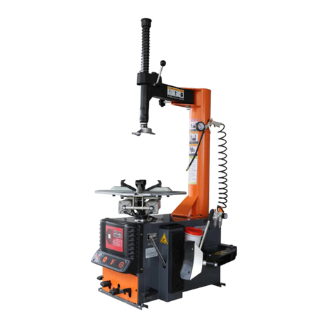
24” SEMI AUTOMATIC TIRE CHANGER
MODEL:TMG-TC24
•First, we should confirm the integrity of the product before installing and debugging, to ensure that the product has not
been changed.
•The manual is a part of the product, please put it in the place where you can find it at any time.
•In the installation process, if the warning signs are damaged, contact the manufacturer in time to replace the defect.
WARNING - Risk Of Explosion. This Equipment Has Internal Arcing Or Parking Parts Which Should Not Be Exposed To
Amenable Vapors.
Do Not Use Below Garage Floor or Grade Level.
ATTENTION - Risque d,explosion. Cet d quipement possdde un arc intdrieur ou des pidces de stationnement qui ne
doivent pas dtre exposes aux vapours inflammables.
Ne pas utiliser au-dessous du plancher de garage ou niveau de grade.
PRODUCT MANUAL
WWW.TMGINDUSTRIAL.COM TOLL FREE:1-877-761-2819
V2021.05.15

GROUNDING INSTRUCTIONS
1 All grounded, cord-connected tools
In the event of a malfunction or breakdown, grounding provides a path of least resistance for electric current
to reduce the risk of electric shock. This tool is equipped with an electric cord having an equipment-grounding
conductor and a grounding plug.
The plug must be plugged into a matching outlet that is properly installed and grounded in accordance with all
local codes and ordinances.
Do not modify the plug provided - if it will not fit the outlet, have the proper outlet installed by a qualified
electrician.
Improper connection of the equipment-grounding conductor can result in a risk of electric shock. The
conductor with insulation having an outer surface that is green with or without yellow stripes is the
equipment-grounding conductor. If repair or replacement of the electric cord or plug is necessary, do not
connect the equipment-grounding conductor to a live terminal.
Check with a qualified electrician or service personnel if the grounding instructions are not completely
understood, or if in doubt as to whether the tool is properly grounded.
Use only 3-wire extension cords that have 3-prong grounding plugs and 3-pole receptacles that accept the
tool's plug.
Repair or replace damaged or worn cord immediately.
2 Grounded
Cord-connected tools intended for use on a supply circuit having a nominal rating less than 150 V: This tool is
intended for use on a circuit that has an outlet that looks like the one illustrated in Sketch A in Figure 83.1. The
tool has a grounding plug that looks like the plug illustrated in Sketch A in Figure 83.1. A temporary adapter,
which looks like the adapter illustrated in Sketches B and C, may be used to connect this plug to a 2-pole
receptacle as shown in Sketch B if a properly grounded outlet is not available. The temporary adapter should
be used only until a properly grounded outlet can be installed by a qualified electrician. The green-colored
rigid ear, lug, and the like, extending from the adapter must be connected to a permanent ground such as a
properly grounded outlet box.
3 Permanently connected tools
This tool should be connected to a grounded metal permanent wiring system; or to a system having an
equipment-grounding conductor.
Figure 83.1
Grounding methods
WWW.TMGINDUSTRIAL.COM P02/32 Toll Free: 1-877-761-2819

Directory
1 Overview...................................................................................................................... 4
1.1 Important note...........................................................................................................4
1.2 Qualified users..........................................................................................................4
1.3 Notes.......................................................................................................................... 4
1.4 Danger warning signs..............................................................................................5
1.5 Noise standard......................................................................................................... 5
1.6 Training...................................................................................................................... 5
2 Equipment description............................................................................................ 6
2.1 Product introduction.................................................................................................6
2.2 Technical parameters..............................................................................................6
2.3 Transport................................................................................................................... 6
2.4 Figure and part name..............................................................................................7
3 Installation and commissioning instructions................................................... 8
3.1 Pre Installation Preparation....................................................................................8
3.2 Precautions during installation...............................................................................9
3.3 Main installation procedure.................................................................................... 9
3.4 Commissioning and debugging...........................................................................11
4 Operation declaration............................................................................................13
4.1 Operating notes......................................................................................................13
4.2 Disassembly operation process.......................................................................... 11
5 Maintenance, storage and scrap........................................................................ 17
5.1 Maintenance........................................................................................................... 17
5.2 Storage and scrap................................................................................................. 19
6 Fault causes and Solutions................................................................................. 19
7 Assistant data.......................................................................................................... 21
7.1 Electrical circuit diagram.......................................................................................21
7.2 Pneumatic diagram................................................................................................22
7.3 Explosion diagram................................................................................................. 23
8 Pneumatic assist arm(TMG-PAT24).................................................................. 32
WWW.TMGINDUSTRIAL.COM P03/32 Toll Free: 1-877-761-2819

1 Overview
1.1 Important notes
Thank you for your purchase and use of this product. Please read the instruction
carefully before installing and operating the tire, so as not to cause unnecessary
damage.
Without the approval of the company, any user shall not change the parts and
structure of the machine without permission.
1.2 Qualified users
After professional training of personnel can operate and use the product.
Electrical appliances must be operated by the normal electrician.
Non-professional and non trained personnel do not come close to the product use
area.
1.3 Notes
Before using the product, please carefully read every part of the manual, especially
the operation of the safety and mechanical maintenance of the part.
Use the tire assembly machine must be operated by professional training personnel.
Tire disassembly is forbidden to use in explosive gas.
Before the machine is connected, the user must ensure that the use of power and
gas supply and mechanical requirements, the circuit system must be operated by
professional staff.
In the operation process, do not face close to the turntable, so as to avoid dust and
other debris hit the operator's eyes. In order to ensure safety, mechanical operation,
to be careful, do not touch the inflatable pedal, so as to avoid accidents.
To tire inflation operation must be very careful, strictly according to the instructions
for operation, if the tire suddenly burst, tire assembly machine design and structure
is not to protect the operator's personal safety (or any mechanical in the vicinity of
the kind).
Operation of the tire changer, necklace, loose clothing, etc., may give the operator to
bring personal injury.
In the process of removing or installing the operation of the tire, the turntable has
always been to ensure that the clockwise rotation; if there is a counter clockwise
rotation indicates that the turntable is a failure or operator error.
Manufacturers are responsible for the damage caused by the use of other parts of
the manufacturer or the damage of the safety device.
Periodically check the oil mist, oil, if the oil level is low and need to unscrew the oil
cup and then add. Oil mist using models for ISO Hg and viscosity for ISO vg32 oil
mist special oil (such as: Esso Fedis k32, 1405, Mobil Vacouline, KLUBER32)
If the product is not used for a long time, please user A. disconnect all power supply,
B. and lubricate the turntable fixture slide to prevent oxidation.
WWW.TMGINDUSTRIAL.COM P04/32 Toll Free: 1-877-761-2819

when deciding to scrap equipment, to determine the total energy of all the energy to
be cut off, according to the relevant laws and regulations for all non-ferrous metals
and non-ferrous metal scrap processing.
1.4 Danger warning signs
1.5 Noise standard
The noise of the tire changer shall be less than 70dB. for your health, and it is
recommended that you place a noise meter in your operating area.
1.6 Training
We will be happy to help you in this regard, as we have to train the staff to operate and
use the tire assembly machine.
Figure1
WWW.TMGINDUSTRIAL.COM P05/32 Toll Free: 1-877-761-2819

2 Equipment description
2.1 Product introduction
This semi-automatic tire changer is a half automatic, convenient and quick disassembly
and installation of wheel size of 10” to 24”, the tire width of 4-1/2"~15 "and the diameter
of the tire is 41".
2.2 Technical parameters
2.3 Transport
The machine must be packed in the original factory, and placed in the position specified
in the packing box. It must be carried out by a forklift truck or other tool with the
corresponding lifting capacity to move the packing machine.
Special points
Technical parameters
Outer rim
10"-22"
Inner rim
12"-24"
Maximum tire diameter
41"
Maximum tire width
15"
Pressing force (l45psi)
2500kg
Operating air pressure
90—115psi
Maximum charge pressure
50psi
Power supply voltage
AC 120V 60Hz
Motor power
12.5Amp
Outline dimension
968x992x1800mm
Net weight
190kg
Working state noise
<70dB (A)
Figure2
WWW.TMGINDUSTRIAL.COM P06/32 Toll Free: 1-877-761-2819

C: inflatable gun E: hand wheel G: clamp
I:changing head K: locking handle M:operating arm
N: horizontal pendulum arm P:column Q: oil water separate
R:tire pressing device S: tire pressure rubber T: crowbar
U: tire-pressing pedal VI, V2: moving jaws pedal Y: turntable
Z:reversing pedal of table!
2.4
Figure and part name
Figure3
WWW.TMGINDUSTRIAL.COM P07/32 Toll Free: 1-877-761-2819

3 Installation and commissioning instructions
3.1 Installation Preparation
3.1.1 Installation location
The installation location of the machine must be in line with the standard of the installation
work.
The tire changer need to be installed in the main power supply and compressed air
system.
Equipment installation location should be at least up to the standard shown in Figure
4 and 4-a, which can ensure the normal operation and the machine parts are not
subject to any restrictions.The tire changer is forbidden to use in explosive gas.
Figure4
Figure4-a
WWW.TMGINDUSTRIAL.COM P08/32 Toll Free: 1-877-761-2819

3.1.2 Installation equipment and tools
Installation equipment and tools
3.1.3 Inspection products
After receiving the product, please check the machine packaging,transport and wet
damage phenomenon, if shipping damage or soaked by rain, please don't open the
package, please contact the seller. Such as damage has been found in the packaging
but still unpacked, missing pieces or some parts can not be used and accidental injury
etc.,I will not bear any responsibility.
3.1.4 Unpacking
Check the packaging damage and the
rain and other damage phenomenon,
using the tool unpack the packing as
shown in Figure 5, please dispose of
packaging box, lest the environmental
pollution.
Check the condition of the machine,
in accordance with the packing list to
check if there is any damage or lost,
once found contact the dealer and
manufacture immediately. If you find
that the leakage but still installed, we
will not assume any responsibility. If
you have any questions, please do not use the machine, the supplier
contact.
3.2 Precautions during installation
All bolts must be tightened.
Power cord, no broken skin, no broken pipe, and other damage.
3.3 Main installation procedure
3.3.1 Standard configuration installation
The first step: unscrew wooden pallet fixing screws, tire changer placed at the
installation site, (installation site must conform to the requirements.
The second step: as shown in figure 6-a, unscrewing the 6 bolts from the box, the
column is installed in the machine box on the specified position, tighten the 6 bolts.
The third step: as shown in figure 6-b, after the installation of the column, such as
Figure5
WWW.TMGINDUSTRIAL.COM P09/32 Toll Free: 1-877-761-2819

the degree of tightness of the arm is not suitable, customers can adjust the tightness
of the elastic nut (according to the customer's own work effect, can not adjust)
The fourth step: as shown in the figure 6-c, ensure the machine source and
compressed air system is connected. * Note: prior to connect all the energy, ensure
the machine installation conditions conform to a uniform requirement.
The fifth step: as shown in Figure 6-d, stepping on the pedal which controls the
cylinder of pressing tire, the piston rod of the cylinder can be inserted.
The sixth step: as shown in figure 6-e, I the spade device is installed in the bearing,
the screw is inserted into the hole, do not use wrench to tighten the nut. II make the
cylinder piston rod go through the hole in the rotating pin, screw the nut, but do not
tighten.III The spring is hung at the point of the box body and the pressing-tire
spade.
The seventh step: as shown in figure 6-g, 6-f, tighten the screw on the pressing-tire
assembly device and the screw on the piston rod of pressing tire cylinder.
Figure6-a
Figure6-b
Figure6-c
Figure6-d
Figure6-e
Figure6-f
Figure6-g
WWW.TMGINDUSTRIAL.COM P10/32 Toll Free: 1-877-761-2819

3.3.2 Check the project table after installation
No.
Inspection item
Yes
No
Remarks
1
Whether the power supply voltage is
consistent with the requirements of the
2
Whether the components are installed
correctly
3
Whether the bolts, screws, nuts are tightened
Note: Please fill in the inspection item list after the installation is finished.
3.4 Commissioning and debugging
Commissioning
After the installation of the machine but before the connection with the power supply,
it is necessary to determine the user's power supply, the gas source and the
requirements of the machine is consistent.
The machine is connected to the circuit, the circuit must be fitted with a fuse that is in
line with the operating rules. The automatic circuit breaker of 25A is required to be
operated by professional personnel. The power plug of the tire changer is provided
with the customer.
As shown in Figure 7, the compressed air system is connected to the machine by a
pipe joint (Q) on the side of the tank.
Figure 7
WWW.TMGINDUSTRIAL.COM P11/32 Toll Free: 1-877-761-2819

Debugging
Step 1: turn on the power and gas supply, step the pedal (Z), turntable (Y) should be
clockwise. Raise the pedal (Z), the turntable (Y) should be anti-clockwise rotation. (If the
turntable is opposite to the specified rotation direction, the position of the two lines in the
three-phase plug should exchange position.)
step 2(U), start the pressing-tire spade device (R); when the pedal is released, the
pressing-tire spade device (R) to return to the original position.
step 3pedal (VI), open the 4 clamps(G); step pedal (V2), the 4 clamps (G) will be closed.
Work head adjustment
Work head position in factory is adjusted in accordance with the size of 14” wheels,
due to the size, shape and structure are different, so you need to adjust the position
of the working head according to the actual wheel size.
The specific operation as follows: as shown in the figure 8-a. Using comer in hand
with an open-ended wrench to release the No. 1,2,3 parts, screwing the hand wheel
(E) on the left side of the column, front of the mounting head (I) should be adjusted
within the range as shown in figure 8-b. Adjusting the end of the mounting head (I) to
the working position according to the rim position (because everyone has a different
way of working, so there is no specific standard).
Fixed (I) working position, using tools tighten the screw of No.3 and No.2 in order,
ensure that when locking screw, the working position of working head (I) has not
changed, using tools to tighten the No.l bolts in figure 8-a (Note: the above bolts and
the top screw must be locked tightly, can not be loosened).
Pull the locking handle (K),loosen manipulator (M), move up the mounting head (I)
to the range shown in the figure 8, then pull the locking handle (K),lock manipulator
(M),at the mounting, head (I) position should be is fixed in the position shown in
figure 8 and figure 8-b.
Figure8
Figure8-a
Figure8-b
WWW.TMGINDUSTRIAL.COM P12/32 Toll Free: 1-877-761-2819

4 Operation declaration
4.1 Operating notes
Check the connection of air pipe is in place, ensure that no air leakage, ensure the
operation space to meet the requirements, then start work.
Before any operation, the gas in the tire is needed to be released , and the balance
block of the tire balancing device is removed.
4.2 Disassembly operation process
4.2.1 pressing tire
Check whether the gas has been released over. If not, please release the gas
completely, close the clamps on the turntable, and straighten the turntable in order
to avoid the damage to the rim in the process of pressing tire.
As shown in Figure 9,10, the tire need to be leaned on the rubber mat which is on the
right side of the semi automatic tire changer (S), ( Note: it must be very careful to
carry out the pressing operation. When the pressure plate is operated, the pressure
relief arm will swing rapidly and powerfully, and any object in the range of the
pressure arm is dangerous.
As shown in Figure 10, make the pressing-tire spade R close to the rim edge for
Figure10
Figure9
WWW.TMGINDUSTRIAL.COM P13/32 Toll Free: 1-877-761-2819

about 2-3cm, (Note: the pressing-tire spade is to be placed on the wheel rather than
the rim).
As shown in Figure 9, step on the pedal (U) and start the tire pressing device. When
the tire pressure shovel completed operation or the wheel edge goes away from the
rim, release the pedal. Gently rotating the tire, repeat the same operation to the
other place of the tire.
4.2.2 Tire disassembly
After pressing tire, the rim edge should be coated with special lubricating fluid, make
the position of the pedal (VI) be in parallel with (V2), the tire should be fixed on the
clamp (G) , make the clamp lock the rim tightly by steeping on the pedal (V2) (Note:
make sure that the rim is locked tightly by the clamps).
Lower operating arm (M), until the disassembly head (I) is supported on the rim of the
rim, lock it with the lock handle (K). In this process, as shown in figure 8-b, figure 8,
the operating arm (M) is locked in a fixed position in the vertical direction, and the
head (I) is moved to the top of the rim of the 2-3.5mm. Once the operating arm is
locked in the vertical direction, As shown in Figure 14, you must use the left hand
wheel (E) which is on the horizontal swing arm (N) to remove the rim of the head (I)
(about 2-3.5mm).
As shown in Figure 11, insert into the crowbar (T) between the tire edge and the
mounting head (I), make the tire edge hang on the disassembly head (I) outward,
keep the crowbar (T) in this position, slam the pedal (Z) to make turntable (Y) rotates
Figure 8-b
Figure 14
Figure 8
WWW.TMGINDUSTRIAL.COM P14/32 Toll Free: 1-877-761-2819

clockwise, until the tire is completely removed from the wheel rim by the crowbar
(T).(when the rotating wheel is running, the other parts of the body should be as far
away as the moving parts, so as not to be injured).
4.2.3 Tire mounting
The special lubricant is coated in the rim, it can prevent the rim flange is damaged,
and can make the installation more convenient. Move the tire, make the rim flange
go through bottom which in the front of the mounting head (I), along the mounting
head (I), make the rim flange be on the top which at the rear of the mounting head
(I).
As shown in Figure 13, pressing the flange into the groove of rim with hand, step
pedal (Z), make the turntable rotates clockwise, until the rim flange falls completely
into the rim. (hands and the other parts of the body are to be as far away as possible
from the operating arm (M), in order to avoid accidents.
Note: in the process of removing or installing the tire, the turntable has always been
to maintain the clockwise rotation; if the counter clockwise rotation indicates that the
turntable is a fault or an operator error.
Figure 11
Figure 12
WWW.TMGINDUSTRIAL.COM P15/32 Toll Free: 1-877-761-2819

4.2.4 Air inflation
Note: the pneumatic operation of the tire must be very carefully, strictly according to
the following instructions for operation, if the tire suddenly burst,
the design and structure of semi-auto tire changer is not able to protect the
operator's personal safety (or anything in the vicinity of the machine. In the process
of charging, as far as possible, make hands and the body be far away from the tire),
recommend using professional inflatable tools (inflatable cage or other protective
device for the tire inflation).
The burst of the tire may cause severe damage to the operator or even death.
Before charging, check whether the tire was damaged.
Remove the tire from the turntable, if you need a greater inflation pressure, you can
place the tire into a special protective cage to continue to inflate it, use the
pneumatic gun provided by the tire changer to inflate, according to the following
steps to complete: first, connect the pneumatic nozzle to the tire valve (as shown in
Figure 13), second, confirm whether the tire diameter is consistent with the diameter
of the rim, third, release the trigger of the gas gun and control the pressure of the
pressure gauge in the process until the tire is fit to the rim, at last, continue to inflate,
and often check the inflation gauge pressure until the pressure reaches the specified
value of the tire. (Note: use the inflated gun to inflate the tire, regularly check the
pressure of the inflation gauge).
Figure 13
WWW.TMGINDUSTRIAL.COM P16/32 Toll Free: 1-877-761-2819

5 Maintenance, storage and scrap
5.1 Maintenance
5.1.1 Maintenance
Prohibit unauthorized personnel for maintenance operation. To extend the service
life of the tire changer, maintenance should be performed according to the
requirements of the manual. If the machine is not maintained regularly, the operation
and reliability can not be guaranteed, and even cause danger to the operator or the
people in the vicinity of the machine. Before any maintenance operation, circuit and
gas supply device must be disconnected ,tum off the switch. In order to release the
pressure of the air from the line, it is necessary to press the pedal 3-4 times.
It must be professional staff using the original spare parts do the timely replacement
of damaged parts. The safety device (safety valve, control valve) of the
unauthorized removal or replacement is a violation of state regulations on work
safety. (Note: the manufacturer is not responsible for damage caused by the parts of
other manufacturer and the damage caused by the disassembling of the safety
device).
5.1.2 Tending
Regular use of diesel oil to clean the turntable, to prevent the formation of dirt. Daub
lubricating oil in the skidway of the clamps.
As shown in figure 15-a, control oil mist level that in the oil mist device, if the oil level
is lower, you need to unscrew the oil F, and then as figure 15-a.,control oil mist level,
HG ISO and viscosity of VG32 ISO type oil mist is recommended.(like: ESSO Febis
K32, MOBIL Vacouline 1405, KLUBER32). when stepping the pedal 3 to 4 times,
check whether there is oil drops into the oil cup F, if not, adjust screw D.
As shown in figure 15-b, 20 days after the first use of the machine, re-tighten the
screw A and B that is in the clamps.
As shown in figure 15-c, machine horsepower is not enough, check the triangle belt
of the motor by the following steps: (before any operation, to cut off the power) first,
Unscrew the 4 screws on the side of the box, remove the left side protective plate of
the tire changer, second, use special adjustment
screw X (Figure 15-c) that is in the motor support base to adjust the triangle belt.
As shown in figure 15-d, If the (I) lock is not good or can not be stopped at the top of
the 2mm, it is necessary to adjust the nut on the operating arm.
As shown in figure 15-e, when cleaning or replacing silencer which controls the
WWW.TMGINDUSTRIAL.COM P17/32 Toll Free: 1-877-761-2819

opening or closure of the clamps(G), follow the following steps: first, unscrew the 4
screws on the side of the box, remove the left side protective plate on the tire
changer.
Second, in the pedal (VI, V2) system which controls the opening or closure of the
clamps(G), unscrew silencer. Clean with compressed air nozzle, if damaged, replace
with the same parts.
Figure 15-a
Figure 15-b
Figure 15-c
Figure 15-d
Figure 15-e
WWW.TMGINDUSTRIAL.COM P18/32 Toll Free: 1-877-761-2819

5.2 Storage and scrap
Storage
If you want a long time storage of machine, please disconnect all the energy supply,
and lubricate the skidway of the clamps on the turntable to prevent oxidation.
Scrap
In accordance with the law of the metal and nonmetal for scrap processing. In the
specified place release the oil inside the machine.
6 Fault causes and solutions
Note: if you can not solve the failure, please contact the manufacturer to provide help.
We will be the first time to help you to solve the failure. Provide the relevant fault
information and fault pictures, thus the manufacturer can get rid of the trouble at the
fastest speed.
Failure phenomenon
Failure cause
Resolvent
Unidirectional rotation
of the turntable
Universal steering switch
damage
Replace universal steering
switch
Rotary table does not
rotate
Triangle damage
Replace triangle belt
Universal steering switch
damage
Replace universal steering
switch
Motor fault or line fault
Check motor and external
plug or socket
Rotary clamp opening /
closing speed is slow
Muffler blockage
Clean or replace muffler
The turntable can’t
lock the rim correctly
Clamps have trouble
Replace clamps
Rotary cylinder has trouble
Replace cylinder or repair
cylinder sealing ring
WWW.TMGINDUSTRIAL.COM P19/32 Toll Free: 1-877-761-2819

Working head can
touch the rim
Lock plate adjustment is not
correct or faulty
Adjust or replace the locking
plate
Working head screw loose
Tighten screws
The pedal is not
located at work
Return spring has trouble
Replace return spring
Operating difficulties of
the tire device
Muffler blockage
To clean or replace the
silencer
Cylinder sealing ring
damage of pressure device
Replace sealing ring
WWW.TMGINDUSTRIAL.COM P20/32 Toll Free: 1-877-761-2819
Other manuals for TMG-TC24
1
This manual suits for next models
1
Table of contents
Other TMG Tyre Changer manuals
Popular Tyre Changer manuals by other brands

SICE
SICE S419 instruction manual

Hofmann Megaplan
Hofmann Megaplan MEGAMOUNT 551 Use and maintenance instructions

SMART-Workshop
SMART-Workshop TIRE TRUER operating manual

ATLAS PLATINUM
ATLAS PLATINUM PTC 500 Use and maintenance instruction manual

Sealey
Sealey TC962.V2 instructions

Launch
Launch TWC Series manual