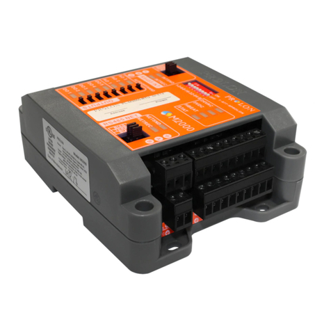
TMS SDP-CH1-A1-TB User manual

TMS Lite SDP-CH1-A1-TB LIGHTING CONTROLLER UNIT
SDP-CH1-A1-TB
Lighting Controller Unit
(Continuous and Pulse Mode)
USER MANUAL

TMS Lite SDP-CH1-A1-TB LIGHTING CONTROLLER UNIT
1
Table of Contents
Table of Contents.................................................................................................................................... 1
Hardware ................................................................................................................................................ 2
Packing List.......................................................................................................................................... 2
General Description ................................................................................................................................ 3
Specification of SDP-CH1-A1-TB.......................................................................................................... 3
Panel Label Description........................................................................................................................... 4
SDP-CH1-A1-TB ................................................................................................................................... 4
Connections ............................................................................................................................................ 5
Power Input & Trigger Input Connector ............................................................................................ 5
Light Output Connector ...................................................................................................................... 5
SDA-CH1-A1-TB Operation Mode ........................................................................................................... 6
Auto Current Detection ...................................................................................................................... 6
Continuous Mode ............................................................................................................................... 7
Pulse Mode ......................................................................................................................................... 7
Pulse Mode Current Multiplier ........................................................................................................ 8
Input Signal ............................................................................................................................................. 9
Drawing Layout ....................................................................................................................................... 9
Accessories............................................................................................................................................ 10
24V Power Supply ............................................................................................................................. 10
Cable Selection.................................................................................................................................. 11
Cable Information ................................................................................................................................. 12
Power Cord Information ....................................................................................................................... 13
Revision Notes
Revision
Date
Description
Authors
1.0
2018-10-18
Initial version.
KF Lam
1.1
2018-11-19
Second version.
KOKWAH

TMS Lite SDP-CH1-A1-TB LIGHTING CONTROLLER UNIT
2
Hardware
Packing List
Please ensure the following items are in the package:
SDP Series Controller Package
•SDP-CH1-A1-TB
•EXT-FL-M12F-3M-24V Cable x1 (optional)
•EXT-FL-24V-3M Cable x1 (optional)
•Adaptor 24V x1 (optional)
•User Manual x1 (download from the link below)
Link for user interface and user manual from TMS LITE website:
http://tms-lite.com/product/sdp-series-3/

TMS Lite SDP-CH1-A1-TB LIGHTING CONTROLLER UNIT
3
General Description
Introduction
The SDP-CH1-A1-TB controller provides intensity control of LED lighting for machine
vision applications. The SDP-CH1-A1-TB automatically detects the operating current of the
LED light and can generate output pulses at as high as 6 times of the operating current..
Front Panel
Specification of SDP-CH1-A1-TB
Lighting Output
No. of lighting output
1 per channel
Min. current output
50mA
Voltage
Continuous Mode : 24V
Pulse Mode: 50V Max
Output current
Continuous Mode: 2A Max
Pulse Mode : 4A Max
Input Power Supply
Power rating
24V
Input Current
Minimum 2.5x LED Light
Operation Mode
Continuous Mode
Output Voltage : 24V
Output Current :50mA~2000mA
Pulse Mode
Trigger Input Voltage : 3.3V~24V
Overdrive Output Voltage : 24V~50V
Overdrive Output Current : 50mA~4000mA
Pulse Width ≤10ms
Duty Cycle ≤10%
Response Time ≤10μs
Remark:
•Maximum lighting rating can be applied is 2A±10%. Fail to do so may cause the
controller malfunction.

TMS Lite SDP-CH1-A1-TB LIGHTING CONTROLLER UNIT
4
Panel Label Description
SDP-CH1-A1-TB
Operation Mode (Pulse Mode /
Constant Mode) Switch
Power Input
Restart Button
Light Output
NPN/PNP Signal
Current Multiplier
1x, 2x & 3x
Status Indicators

TMS Lite SDP-CH1-A1-TB LIGHTING CONTROLLER UNIT
5
Connections
Power Input & Trigger Input Connector
Pin
Description
1
24V
2
GND
3
TRIG +
4
TRIG -
Light Output Connector
Pin
Description
1
LIGHT+
2
LIGHT-
1 2 3 4
1 2

TMS Lite SDP-CH1-A1-TB LIGHTING CONTROLLER UNIT
6
SDA-CH1-A1-TB Operation Mode
SDP can operate in 2 different modes: continuous mode and pulse mode. The operation mode
can be set by the Operation Mode Switch in the front panel. (Fig - 1.0)
Fig - 1.0
Auto Current Detection
The SDP-CH1-A1-TB Controller detects the LED current automatically while power-up
(Power Green LED Fig - 1.2). Users can use the Restart Button (Fig-1.1) to restart the
detection process.
The RUN LED (Fig - 1.2) in the front panel will blink at a higher rate to indicate the
controller is performing the current detection process. When the detection process is
finished, the “RUN LED”will blink at a lower rate. If there is any error, the red LED
status 1, will be turned on.
The Status 2 Led turns on while Input Pulse Signal is active, the duration of the turn on
period is the same as the input signal.
Fig -1.1 Fig - 1.2

TMS Lite SDP-CH1-A1-TB LIGHTING CONTROLLER UNIT
7
Continuous Mode
Continuous mode offers continuous lighting intensity to fully ON (100%), the output voltage
of the controller is 24V and the maximum output current is 2A.
Pulse Mode
In the pulse mode, the controller outputs a pulse to the LED when received a trigger signal.
The duration of the output pulse is the same as the duration of the trigger pulse. The
maximum pulse width is 10ms
Pulsing provides high current and short interval triggering for applications that require high
intensity and high precision.
As the overdrive percentage increases, the brightness of the lighting also increases.
Pulse width is the duration of the lighting ON time.
Remark:
•Maximum pulse width is 10mS and maximum duty cycle for lighting pulse is 10%. Fail
to do so may cause the controller malfunction.
•Input response time is ≤10us
•The Output Width follows the same pattern as the Lighting Pulse Width
Pulse Width
External Trigger
Lighting Pulse
10% Duty
Cycle
Input
Response Time

TMS Lite SDP-CH1-A1-TB LIGHTING CONTROLLER UNIT
8
Pulse Mode Current Multiplier
The current of the output pulse can be set via the Current Multiplier Switch.
DIP Switch
DIP SWITCH NO
1
2
3
4
Multiplier
CURRENT PULSE 1x
0
0
0
0
1
CURRENT PULSE 1x
1
0
0
0
1
CURRENT PULSE 2x
0
1
0
0
2
CURRENT PULSE 3x
1
1
0
0
3
Limitations
In order to protect the SDP-CH1-A1-TB and LED light from overloading, the maximum
current, the duration and the duty cycle of the output pulses are limited. The maximum
current of a pulse is 4A. The maximum pulse duration is 10ms. The maximum duty cycle is
10%.

TMS Lite SDP-CH1-A1-TB LIGHTING CONTROLLER UNIT
9
Input Signal
Input signal is optional and used to turn on the lighting based frequency/duty cycle of input
signal. The turn on time of lighting is adjustable and depending on the value of pulse width.
Note: Pulse width adjustment from 0s to 10ms.
IN(+) is common positive input. Acceptable voltage is from 3.3-24VDC.
IN(-) is common negative input. Should be connected to GND.
The trigger signal can be acknowledge by controller on the rising edge or falling edge.
Drawing Layout

TMS Lite SDP-CH1-A1-TB LIGHTING CONTROLLER UNIT
10
Accessories
Additional accessories that can be used with SDP-CH1-A1-TB controllers.
•24V power supply
•Lighting cable
24V Power Supply
MODEL
SPECIFICATIONS
24V POWER SUPPLY WITH POWER CORD
•24V-2.5A-UK
(24V ADAPTOR WITH POWER
CORD UK)
•24V-2.5A-US
(24V ADAPTOR WITH POWER
CORD US)
•24V-2.5A-EU
(24V ADAPTOR WITH POWER
CORD EU)

TMS Lite SDP-CH1-A1-TB LIGHTING CONTROLLER UNIT
11
Cable Selection
** XX = Length
** XX = Length
MODEL
POWER
LENGTH
EXT-24V-F-XX
24V
3M
5M
MODEL
POWER
LENGTH
EXT-FL-M12F-XX
24V
3M
5M

TMS Lite SDP-CH1-A1-TB LIGHTING CONTROLLER UNIT
12
Cable Information
i) EXT-FL-24V-3M
Extension Cable of 3 Meter with SM connector
ii) EXT-FL-M12F-3M-24V
Extension Cable of 3 Meter with M12F connector

TMS Lite SDP-CH1-A1-TB LIGHTING CONTROLLER UNIT
13
Power Cord Information
The cable length is 1.8 Meter length of power cord.
240VAC Power Cord (UK)
220VAC Power Cord (EU)
110VAC Power Cord (US)

Thank you for downloading this document from
www.machine-vision-shop.com
If you have any questions, you need help composing the
right package for your application or do you want to order?
Feel free to contact us via e-mail at sales@vision-
consultancy.nl or visit our webshop.
Our vision experts are happy to help you.
VISION CONSULTANCY
Robert Schumandomein 2
6229 ES Maastricht
The Netherlands
+31 (0) 438 522 651
www.machine-vision-shop.com
Natascha Overhof
Christian Crompvoets
© 2021 Vision Consultancy
Scan me to visit
machine-vision-shop
Table of contents
Other TMS Controllers manuals
