York YK-SMU2x0-0 User manual

428546-YIM-C-1110
YCCS System Manager and Zone Coordinator Installation Instructions 1
Applications
The York Commercial Comfort System (YCCS) System
Manager and Zone Coordinator supervisory controllers
bring an entirely new generation of Building
Automation System (BAS) technology to light
commercial systems. These supervisory controllers
use Internet Technology (IT) and BACnet®
Master-Slave/Token-Passing (MS/TP) communication
to provide supervisory level control of light commercial
BASs.
All System Manager models and select Zone
Coordinator models feature an intuitive color
touch-screen User Interface (UI) that provides the
ability to schedule, trend, and adjust parameters for the
entire building. The supervisory controllers require no
programming and have predefined point lists for the
mechanical equipment configuration used within the
facility. Both devices support remote access via a
standard Web browser or any computer connected to
the building network.
North American Emissions Compliance
United States
Canada
Installation
Follow these guidelines when installing the System
Manager or Zone Coordinator:
• Transport the System Manager or Zone
Coordinator in the original container to minimize
vibration and shock damage.
• Do not drop the controller or subject it to shock.
• Do not open the controller housing. The controllers
have no user-serviceable parts inside the housing.
Parts Included
One System Manager or Zone Coordinator with
removable mounting base.
Materials and Special Tools Needed
• three fasteners appropriate for the mounting
surface (M4 screws - #8 screws)
• wire strippers
• small flat-head screwdriver
• 22 AWG (0.65 mm) 3-conductor, twisted, shielded
cable with a drain wire
Note: This drain wire is used only to group the
shielded cable. Do not use this drain wire as a
connection to the board.
• wire nuts for 22 AWG drain wire
• electrical tape
This equipment has been tested and found to
comply with the limits for a Class A digital device
pursuant to Part 15 of the FCC Rules. These limits
are designed to provide reasonable protection
against harmful interference when this equipment is
operated in a commercial environment. This
equipment generates, uses, and can radiate radio
frequency energy and, if not installed and used in
accordance with the instruction manual, may cause
harmful interference to radio communications.
Operation of this equipment in a residential area is
likely to cause harmful interference, in which case
the user will be required to correct the interference
at his/her own expense.
This Class (A) digital apparatus meets all the
requirements of the Canadian Interference-Causing
Equipment Regulations.
Cet appareil numérique de la Classe (A) respecte
toutes les exigences du Règlement sur le matériel
brouilleur du Canada.
YCCS System Manager and Zone Coordinator
Installation Instructions
YK-SMU2x0-0, YK-ZCUxx0-0

428546-YIM-C-1110
YCCS System Manager and Zone Coordinator Installation Instructions2
Dimensions
Accessories
Table 1 lists the System Manager and Zone
Coordinator accessory.
Mounting
Follow these guidelines when mounting the System
Manager or Zone Coordinator:
• Ensure that the mounting surface can support the
supervisory controller and any user-supplied
enclosure.
• Mount the supervisory controller in an upright
position (Figure 1).
• Mount the supervisory controller on a hard, even
surface in wall-mount applications whenever
possible.
If you must mount the supervisory controller on an
uneven surface, be careful not to crack the
supervisory controller housing when tightening the
screws. Use shims or washers to mount the
supervisory controller securely and evenly on the
surface.
• Mount the supervisory controller in areas free of
corrosive vapors, and observe the environmental
limitations listed in the Technical Specifications
section.
• Allow sufficient space for cable and wire
connections (Figure 2).
• Do not mount the supervisory controllers where
ambient temperatures may exceed 50°C (122°F).
• Do not mount the supervisory controller on
surfaces prone to vibration or in areas where
electromagnetic emissions can interfere with
supervisory controller communication.
• Do not obstruct the supervisory controller housing
ventilation holes.
• Do not mount power transformers below the
supervisory controller.
Figure 1: System Manager and Zone Coordinator Dimensions and Configuration, mm (in.)
Table 1: System Manager and Zone Coordinator
Accessory
Code Number Description
Y65T42-0 Transformer, 120/208/240 VAC
primary to 24 VAC secondary, 40 VA
hub mount, Class 2

YCCS System Manager and Zone Coordinator Installation Instructions 3
428546-YIM-C-1110
For applications where the supervisory controller is
mounted inside a panel or enclosure, follow these
additional guidelines:
• Follow the manufacturer’s instructions when
mounting the enclosure.
• Do not install the supervisory controller in airtight
enclosures.
• Do not install heat-generating devices in the
enclosure with the supervisory controller or near
the enclosure that may cause the ambient
temperature to exceed 50°C (122°F).
Mounting the Controller
To mount the controller on a vertical surface:
1. Hold the controller mounting base up to the wall
and mark the location of the wall mount holes
(Figure 2).
2. Drill holes in the wall at the locations marked.
3. Position the mounting base, insert the screws
through the holes in the base, and carefully tighten
the screws.
4. Line up the side tabs on the face of the controller
with the tabs on the mounting base and carefully
snap the face of the controller in place.
Wiring
Power Supply, Network, and Communication
Bus Connections
See Figure 1 and Figure 3 for the location of System
Manager or Zone Coordinator ports, modular jacks,
and terminal blocks.
Power Supply
The Zone Coordinator and System Manager requires a
dedicated Class 2, 24 VAC, 10 VA minimum power
supply.
System Communication/Zone Communication Bus
Port
The YK-SMU2x-0 models support the System Bus. The
YK-ZCUxx0-0 models are designed to support one
System Communication Bus and one Zone
Communication Bus.
Connect a System Communication Bus to the 3-wire
terminal block plug labeled System Bus on the System
Manager (Figure 3).
Table 2: Figure 2 Callout Descriptions
Callout Description
1Surface Mount Conduit/Wire Entry
2Communication/Power Terminal Block
3Surface Mount Conduit/Wire Entry
4Wall Anchor Mounting Hole
5Wall Box Mounting Holes
6Wall Mount Wire Entry
Figure 2: Mounting Base Configuration
(Front View), See Table 2 for Callout Descriptions
FIG:frnt_vw_SMZC
205.9
(8-1/8)
115
(4-1/2)
45.4
(1-13/16)
211.9
(8-3/8)
88.9
(3-1/2)
148.7
(5-13/16)
123
4
5 6
IMPORTANT: Do not overtighten the mounting
screws. Overtightening the screws may damage the
controller housing.
IMPORTANT: Ensure the BAS network wiring
meets the specifications in this section.
IMPORTANT: The 24 VAC power should not be
shared with other network devices. Sharing power
with other network devices may cause noise,
interference, and ground loop problems. You may
damage the controller by sharing power with other
devices.

428546-YIM-C-1110
YCCS System Manager and Zone Coordinator Installation Instructions4
Connect a Zone Communication Bus to the 3-wire
terminal block plug labeled System Bus on the ZC
(Figure 4).
USB Port
The Universal Serial Bus (USB) port connects an
external memory storage device (USB memory stick,
Type U1 or U2) for backing up controller configuration
parameters or for performing upgrades.
Ethernet Port
The Ethernet connection (10 or 100 Mbps) is an 8-pin
RJ-45 network port (Figure 1). Use the Ethernet port to
connect to Internet Protocol (IP) networks for remote
user access.
Optional Internal Modem
Both the YK-SMU2-0 and the YK-ZCUx0-0 supervisory
controllers have an internal modem and a 6-pin RJ-11
modular jack. Insert a standard phone line plug to
connect the internal modem.
Wiring Guidelines
Follow these guidelines when wiring the System
Manager and Zone Coordinator controllers:
• Securely mount the controller base before wiring.
See the Mounting the Controller section.
• Route the supply power wires and communication
cables at least 50 mm (2 in.) away from the vent
slots on the sides of the controller housing.
• Provide slack in the wires and cables. Keep cables
routed neatly around the controller to promote
good ventilation, Light-Emitting Diode (LED)
visibility, and ease-of-service.
Wiring the Controller
To wire the controller:
1. Connect the three System Communication Bus
wires to the 3-terminal block for the System
Manager and/or connect the three Zone
Communication Bus wires for the Zone
Coordinator (Figure 3 and Figure 4).
Note: When the controllers are connected to the
System Communication Bus, you must set the
End-of-Line (EOL) switch to the ON position
(Figure 3 and Figure 4).
2. Connect the 24 VAC power supply wires from the
transformer to the terminal block (Figure 3 and
Figure 4).
Figure 3: System Manager System
Communication Terminal Block Detail
S1 S2
J8 J7 J6
System
Bus Zone
Bus
COM -+COM -+
COM 24V
On
Off
24VAC
COM
COM
SB -
SB +
ZB +
ZB -
COM
EOL
ON
Off
EOL
ON
System Communication
Bus Terminal Strip
End-of-Line (EOL) Termination
Set to ON
24 VAC Power
Input (10 VA)
Not Used
FIG:SM_trm_blk
On
Figure 4: Zone Coordinator System
Communication Terminal Block Detail
S1 S2
J8 J7 J6
System
Bus Zone
Bus
COM -+COM -+
COM 24V
On
Off
24VAC
COM
COM
SB -
SB +
ZB +
ZB -
COM
EOL
ON
Off
EOL
ON
System
Communication
Bus Terminal Strip
End-of-Line (EOL)
Termination
Set to ON
24 VAC Power
Input (10 VA)
Zone Communication
Bus Terminal Strip
FIG:ZC_trm_blk
!
CAUTION: Risk of Property Damage.
Do not apply power to the system before
checking all wiring connections. Short
circuited or improperly connected wires
may result in permanent damage to the
equipment.
IMPORTANT: Exceeding the controller electrical
ratings can result in permanent damage to the
controller and void any warranty.
IMPORTANT: Use copper conductors only. Make
all wiring connections in accordance with local,
national, and regional regulations. Do not exceed
the System Manager or Zone Coordinator’s
electrical ratings.
IMPORTANT: Prevent static electricity discharge to
the controllers. Static electric discharge may
damage the controller and void any warranties.

YCCS System Manager and Zone Coordinator Installation Instructions 5
428546-YIM-C-1110
Note: Power supply wire colors may be different
on transformers not manufactured by Johnson
Controls, Inc. Follow the transformer
manufacturer’s instructions and project installation
drawings for wiring details.
3. Connect the Ethernet communication cable to the
RJ-45, 8-pin Ethernet port (Figure 1).
Note: The Ethernet communication cable is
optional. It is only required for remote access to the
controller.
4. Connect the phone line to the modem port, if using
the internal modem.
Note: The 24 VAC power should be connected to
all network devices so transformer phasing is
uniform across the devices. Powering devices with
uniform 24 VAC supply power phasing reduces
noise, interference, and ground loop problems. The
controllers do not require an earth ground
connection.
Table 3 outlines the System and Zone Communication
Bus limits for the controllers. Table 4 outlines Ethernet
limits in YCCS applications.
Table 3: System and Zone Communication Bus Limits
Category Limits
General System Manager (YK-SMU2xx-0)
Supports one System Communication Bus trunk and daisy-chained field controllers only.
Zone Coordinator (YK-ZCUxxx-0)
Supports one System Communication Bus and one Zone Communication Bus per Zone
Coordinator, and daisy-chained field controllers only.
Number of Devices
Supported System Manager (YK-SMU2xx-0)
Supports up to 38 devices total on the System Communications Bus, including:
• up to 10 Zone Coordinators
• up to 24 factory- or field-mounted RoofTop Unit (RTU) controllers
• up to 4 Input/OutputModule (IOM) controllers
• up to 24 TEC Series thermostat controllers
Note: The total number of TECs and RTU Controllers combined cannot exceed 24 devices.
Zone Coordinator (YK-ZCUxxx-0)
In a Changeover Bypass (COBP) system, supports up to 26 devices total on the Zone
Communication Bus, including:
• up to 24 zone damper controllers
• 1 factory- or field-mounted ChangeOver Bypass (COBP) RTU controller
• 1 bypass damper controller
In a Variable Air Volume (VAV) system, supports up to 33 devices total on the Zone
Communication Bus, including:
• up to 32 VAV zone damper controllers
• 1 factory- or field-mounted VAV RTU controller
Bus Length System Bus: 305 m (1,000 ft) of cable
Zone Bus: 305 m (1,000 ft) of cable
Cable Type Stranded 0.6 mm (22 AWG) 3-wire twisted, shielded cable with drain wire (preferred).
Stranded 0.6 mm (22 AWG) 4-wire (two-twisted-pairs) shielded cable (acceptable).
Note: The + and - Bus leads must be a twisted pair. On Bus applications using 4-wire cable
(two twisted pairs), isolate and insulate unused conductors.
Terminations One EOL switch in the ON position.
Table 4: Ethernet Limits
Category Limits
General Point-to-point star topology with network hubs/switches.
Line Length and Type 2,012 m (6,600 ft) for plastic/glass fiber optic with external adapter; 100 m (330 ft) CAT5 cable.
Terminations For 10/100 Base-T, no line terminators allowed.

428546-YIM-C-1110
YCCS System Manager and Zone Coordinator Installation Instructions6
Setup and Adjustments
To quickly set up your YCCS network:
1. On each end of the 3-conductor cable, strip the
outside insulation back approximately 2 in.
(51 mm).
2. Tear off excess foil shield, leaving the bare drain
wire and the three insulated conductors.
3. On each end of the three insulated conductors in
the cable, strip the insulation back approximately
1/8 to1/4 in. (4 to 7 mm).
4. Choose a color pattern to follow and insert each of
the three conductors into one each of the three
terminals on the YCCS board communication
connector.
5. Tighten each terminal until the wire is secure.
6. Ground the drain wire at one end only of the
communication trunk. Do this on the last unit in
line.
7. Use an existing hole or drill a hole and insert a
sheet metal screw in the back plate below the
communication connector.
8. Wrap the bare drain wire around the screw and
tighten the screw. This is the only location where
the shield is grounded.
9. Daisy chain the three-conductor wire between the
remaining controller assemblies. Connect the drain
wires together with the wire nuts. Follow the
stripping and connecting procedure in Step 1
through Step 8.
10. Run the cable from the last unit to the location of
the Zone Coordinator. Follow the connection
instructions for the controllers. Figure 5 shows a
typical communication riser.
11. Make sure all the controllers are powered and
operating properly.
12. Go to each controller and repeat Step 1 through
Step 11.
Note: Ensure you observe polarity of each of the
conductors in the communication cable.

YCCS System Manager and Zone Coordinator Installation Instructions 7
428546-YIM-C-1110
S1 S2
J8 J7 J6
System
Bus Zone
Bus
COM
-
+COM
-
+
COM 24V
On
Off
24VAC
COM
COM
SB
-
SB
+
ZB
+
ZB
-
COM
EOL
ON
Off
EOL
ON
S1 S2
J8 J7 J6
System
Bus
Zone
Bus
COM
-
+COM
-
+
COM 24V
On
Off
24VAC
COM
COM
SB
-
SB
+
ZB
+
ZB
-
COM
EOL
ON
Off
EOL
ON
Communication
Connector
Input
Terminals
Address
Switch
AI1 COM
J5
AI2 COM
J6
AI3 COM
J7
AI4 COM
J8
AI5 COM
J9
O
N
1
64
32
16
8
4
2
128
COM
-
+
J3
Communication
Connector
Input
Terminals
Address
Switch
AI1 COM
J5
AI2 COM
J6
AI3 COM
J7
AI4 COM
J8
AI5 COM
J9
O
N
1
64
32
16
8
4
2
128
COM
-
+
J3
Communication
Connector
Input
Terminals
Address
Switch
AI1 COM
J5
AI2 COM
J6
AI3 COM
J7
AI4 COM
J8
AI5 COM
J9
O
N
1
64
32
16
8
4
2
128
COM
-
+
J3
Drain
Wire
Address = 18 Address = 19
Address = 5
S1 S2
J8 J7 J6
System
Bus Zone
Bus
COM
-
+
COM
-
+
COM 24V
On
Off
COM
-
+
J2
COM
AI1
AI2
COM
AI3
AI4
1
64
32
16
8
4
2
128
O
N
24VCOM24VCOM
COM
-
+
J2
COM
AI1
AI2
COM
AI3
AI4
1
64
32
16
8
4
2
128
O
N
24V
COM
24VCOM
Drain
Wire
Drain
Wire
Tape back
Drain Wire
Drain
Wire
Drain
Wire
Address = 4
Address = 6
Address = 7
VAV
Rooftop Unit
VAV
Box
VAV
Box
Single Zone
Unit
Single Zone
Unit IOM Module
Zone Coordinator
Termination Board
Tape Back
Drain Wire
System Manager
Termination Board
Zone Bus
Communication
Trunk
System Bus
Communication
Trunk
24VAC
COM
COM
SB -
SB +
ZB +
ZB -
COM
EOL
ON
Off
EOL
ON
System Communication
Bus Terminal Strip
EOL Termination
Set to ON
24VAC Power
Input (10VA)
Zone Communication
Bus Terminal Strip
Note: Ground the drain wire at
the end of the communication
trunk. Do not allow the drain
wire to contact exposed metal.
Note: Ground the drain wire at
the end of the communication
trunk. Do not allow the drain
wire to contact exposed metal.
Note: Communication trunk must be
22 AWG (0.65 mm) 3-conductor
twisted, shielded cable with drain wire.
FIG:cmn_rsr_SM-ZC
Figure 5: Typical System Communication Riser

428546-YIM-C-1110
YCCS System Manager and Zone Coordinator Installation Instructions8
Communication Bus
Determining the System Manager Address Switch
The System Manager address switch is always set to 0;
therefore, you do not need to determine the System
Manager address.
Determining the Zone Coordinator Bus Address
The Bus address switch sets a unique address for this
controller on the System Communication Bus. The
default address setting is 255 (all ON). You must change
the default address.
Set consecutive addresses 8-17 for Zone Coordinator on
the System Communication Bus. Use sequential
addressing with no gaps in the device address range to
ensure best Bus performance. Table 5 and Figure 7 show
System Communication Bus address switch settings.
Powering On the System Manager and Zone
Coordinator
After applying 24 VAC power, the controllers require
approximately 2 minutes to start up and become
operational. Startup is completed and the controllers are
operational when the home screen appears. The green
RUN LED appears and is on steady.
Disconnecting Power from the System Manager
and Zone Coordinator
The System Manager and Zone Coordinator have no
backup battery power. When the 24 VAC power supply is
disconnected or lost, the controllers are nonoperational.
End-of-Line (EOL) Terminations
Daisy-chained RS485 protocol networks require End-of-
Line (EOL) termination to reduce interference.
Interference is caused by signal reflection that occurs
when data transmissions reach the end of a bus segment
and bounce back (Figure 8). The high baud rates on
Master-Slave/Token-Passing (MS/TP) bus applications
require robust EOL termination and strict adherence to
the EOL termination rules.
Figure 6: Zone Coordinator
Address Switch Detail
8 7 6 5 4 3 2 1
ON
OFF
Front
View from bottom of
Zone Coordinator
Address Switch 255
(All switches shown in
OFF position)
128
64
32
16
8
4
2
1
FIG:ZC_swtch
Figure 7: Zone Coordinator
Address Switch Settings
8 7 6 5 4 3 2 1
ON
OFF
1
2
4
8
16
32
64
128
Address 8
8 7 6 5 4 3 2 1
ON
OFF
1
2
4
8
16
32
64
128
Address 9
8 7 6 5 4 3 2 1
ON
OFF
1
2
4
8
16
32
64
128
Address 10
8 7 6 5 4 3 2 1
ON
OFF
1
2
4
8
16
32
64
128
Address 11
8 7 6 5 4 3 2 1
ON
OFF
1
2
4
8
16
32
64
128
Address 12
8 7 6 5 4 3 2 1
ON
OFF
1
2
4
8
16
32
64
128
Address 13
8 7 6 5 4 3 2 1
ON
OFF
1
2
4
8
16
32
64
128
Address 14
8 7 6 5 4 3 2 1
ON
OFF
1
2
4
8
16
32
64
128
Address 15
8 7 6 5 4 3 2 1
ON
OFF
1
2
4
8
16
32
64
128
Address 16
8 7 6 5 4 3 2 1
ON
OFF
1
2
4
8
16
32
64
128
Address 17
FIG:ZC_swtch_sets
Table 5: System Communication Bus Address
Summary
Address Description
8–17 Zone Coordinator on the System
Communication Bus
IMPORTANT: Wait for the controller to complete
the startup sequence and the RUN LED to appear
before initiating other actions.
No EOL = No Signal Cushioning
(Bounce Back and Noise)
No
EOL
EOL
EOL Provides Signal
Cushioning (No Bounce Back)
FIG:intrfrnc
Figure 8: Interference

YCCS System Manager and Zone Coordinator Installation Instructions 9
428546-YIM-C-1110
On a YCCS System bus or Zone bus, only one EOL
termination is required due to the fewer number of
devices on one bus and the shorter wiring length.
Specifically, the System bus must always have a
System Manager as the EOL device, and the Zone bus
must always have a Zone Coordinator as the EOL
device. Figure 9 shows a YCCS EOL wiring example.
Operation
For information on heating and cooling modes, zone
voting, and other Zone Coordinator and System
Manager functions, refer to the York Commercial
Comfort System (YCCS) Operation Overview Technical
Guide (643517).
For information on creating setpoints and configuring
operating modes, refer to the York Commercial
Comfort System (YCCS) System Manager and Zone
Coordinator Userís Guide (428516).
Figure 9: System Manager and Zone Coordinator EOL Wiring
Input
Output
Module
24V
COM
COM
-
+
BI-1
COM
BI-2
COM
AI-3
COM
AI-4
Monitored Contact
To Temperature,
RH%, CO2Sensor,
Building Pressure,
Light Sensor,
Refrigerant Sensor
To 24VAC
BO-3
BO-2
BO-1
BO-4
COM
Monitored Contact
To Scheduled Item 1
To Scheduled Item 2
To Scheduled Item 3
To Scheduled Item 4
Non-
CCS
HVAC
System
Universal
CV Unit
Controller
24V
COM
Zone Sensor
COM
-
+
AI-1
COM
AI-2
1
2
3
4
BO-1
BO-2
BO-3
BO-4
BO-5
C
R
G
Y1
Y2
W1
W2
COM
AI-6
COM
AI-7
COM
AI-8
COM
AI-4
COM
AI-5
COM
BI-2
SAT Sensor
RAT Sensor
OAT Sensor
To Zone RH% Sensor
To Zone CO2Sensor
APS
Zone Sensor COBP Zone Coordinator
System
Bus
COM
SB-
SB+
EOL
O
N
?
Zone
Bus
COM
ZB-
ZB+
EOL
O
N
?
COM
24V
LAN To 24VAC
System Manager
System
Bus
COM
SB-
SB+
EOL
O
N
Zone
Bus
COM
ZB-
ZB+
EOL
O
N
COM
24V
Modem
LAN To 24VAC
To Phone Line
To Ethernet Hub
VAV Zone Coordinator
System
Bus
COM
SB-
SB+
EOL
O
N
Zone
Bus
COM
ZB-
ZB+
EOL
O
N
COM
24V
LAN To 24VAC
tape
off
CV Unit Controller
COM
-
+
Simplicity Board
Binary
&
ModBus
This end of the Drain Wire
connected to cabinet ground
Other System Bus Devices
AI-1
COM
AI-2
1
2
3
4
Other System Bus Devices
To COBP Zone
Bus Devices
To VAV Zone
Bus Devices
Zone Coordinator must be end of line for zone busSystem Manager must be end of line for system bus
FIG:SM-ZC_EOL
Zone Coordinator must be end of line for zone bus

428546-YIM-C-1110
YCCS System Manager and Zone Coordinator Installation Instructions10
Troubleshooting
Use the following information to troubleshoot the
System Manger and Zone Coordinator.
Status LEDs
The System Manager and Zone Coordinator include
LEDs that indicate communication and alarm status for
the controller. Table 6 lists LED descriptions.
Communication Problems
Several factors may influence the behavior of the
System Communication Bus. In addition, certain
problems can affect the Bus in multiple ways and have
multiple symptoms, which makes the exact diagnosis
difficult. For example, duplicate addresses on the Bus
can degrade performance, make the device go offline,
or stop communication completely.
Incomplete Address
The YK-ZCUxx0-0 Zone Coordinator must have the
address switch set between 8–17 on the System
Communication Bus; other settings prevent the Zone
Coordinator from communicating on the System
Communication Bus.
Duplicate Addresses
Two or more devices on a communication Bus cannot
have the same address. For example, two Zone
Coordinators on the System Communication Bus
cannot both have an address of 8. If two devices on the
same Bus have the same address, performance can
degrade or serious communication problems may
occur. These problems include the devices not coming
online and all communication stopping completely.
Check for duplicate addresses, in the following ways,
depending on the severity of the situation:
• If the Bus performance is degraded, check the
address switch settings at the devices with
unreliable communications.
• If the Bus communication problems are severe,
and no communication is present, or you can not
determine where communication is unreliable,
partition (disconnect and isolate a portion of the
Bus for testing purposes) and test the Bus portion
connected to the System Manager and Zone
Coordinator controllers.
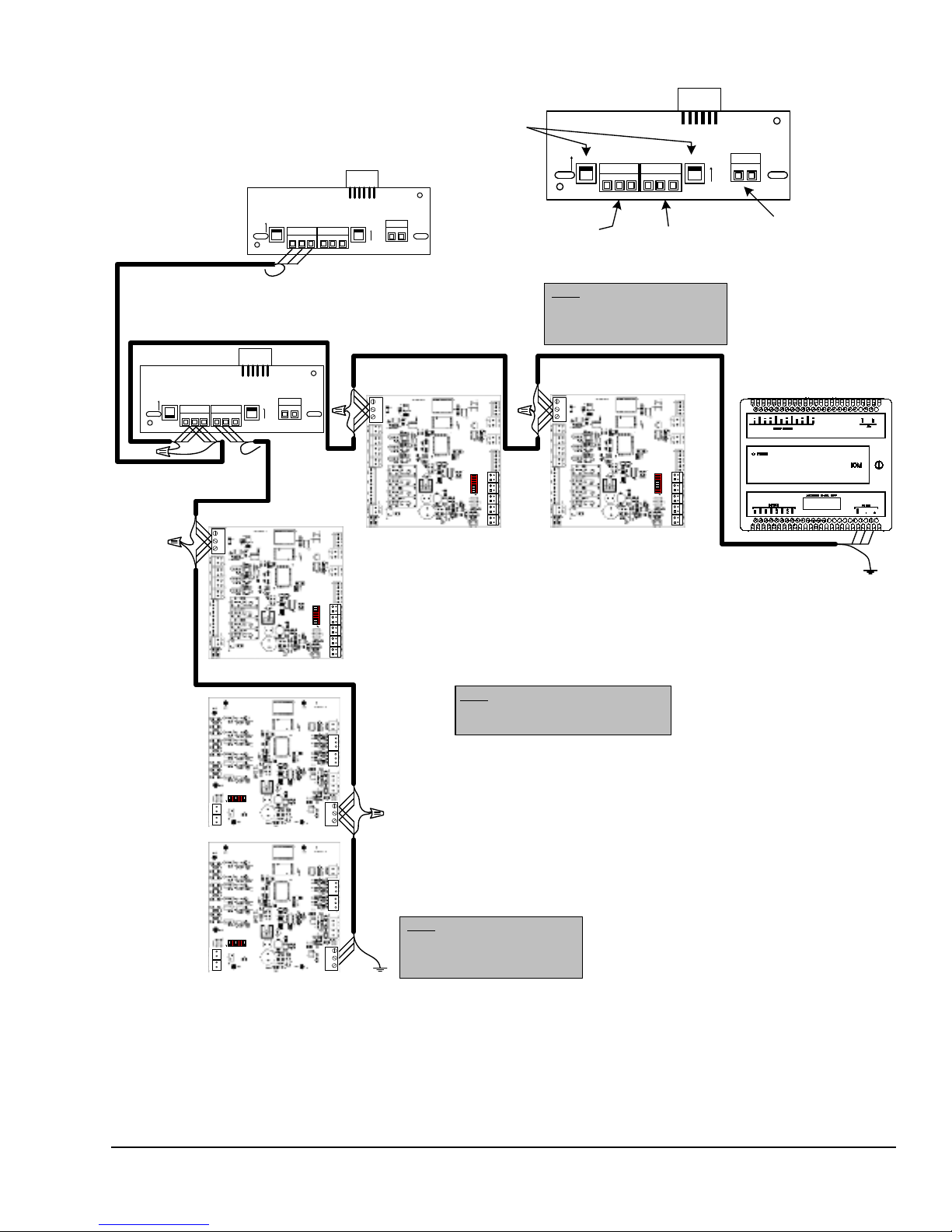
Correcting Physical Communication Bus Problems
The communication bus is subject to a number of
physical factors that can affect performance. Consider
the following list of common physical problems that
affect the communications bus:
• Check status LED to verify power at the controller
•Checkwires
- Verify wire is 22 AWG (0.6 mm) 3-conductor,
twisted, shielded cable.
- Verify shield is continuous and hard-grounded
at one end.
• Check wiring
- Check for and eliminate T-Taps (wire
configurations that create a T shape) and star
configurations.
- Ensure bus is wired in daisy-chain fashion.
- Verify that appropriate devices have three
wires entering and exiting each terminal
(devices at the ends of the trunk do not have
this wiring).
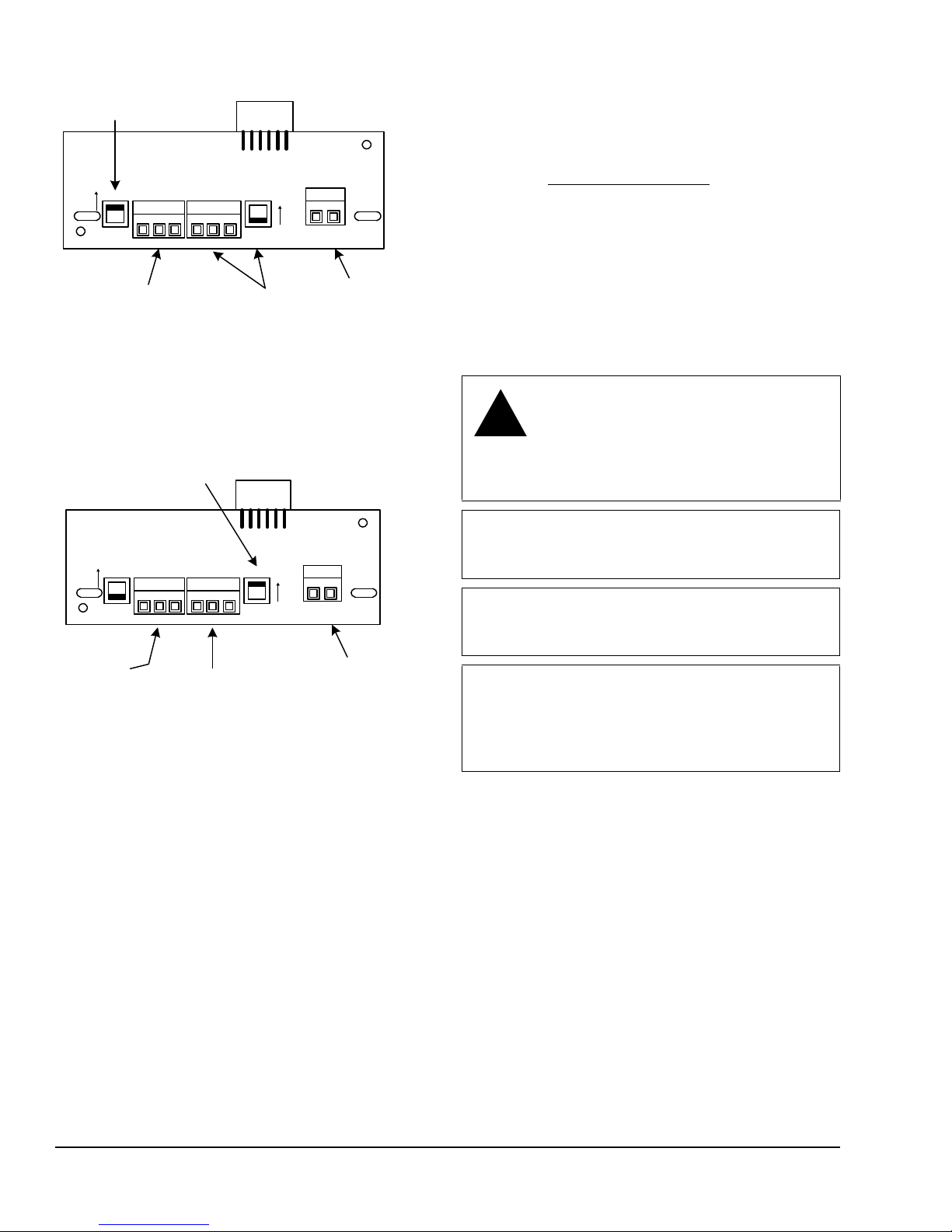
• Check EOL switch settings
- Verify the zone bus EOL switch on the Zone
Coordinator is set to ON and the Zone
Coordinator is located at the end of the zone
bus trunk.
- Verify that only the EOL switch at the end of
the system bus is set to ON and all other
system bus EOL switches are set to OFF.
• Check connections, polarity, and lengths
- Verify communications loops are less than
approximately 304 m (1,000 ft) total in length.
- If you are using one transformer to power
multiple devices, verify the device 24 VAC
power connection follows the polarity of the
common and 24 V terminations.
• Check for opens and shorts
• Check terminations
• Check for sources of interference
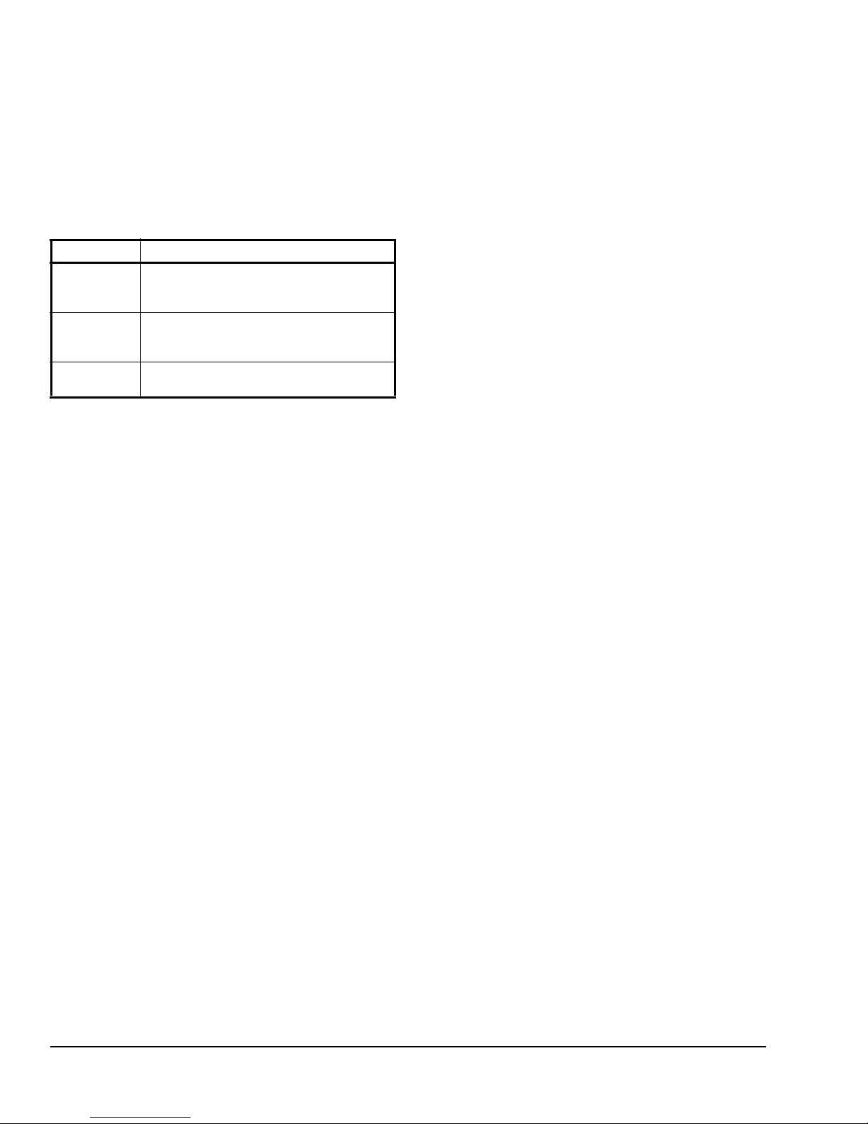
Table 6: Status LEDs
LED Description
Green The controller is getting power from the 24
VAC power supply and unacknowledged
alarms are not present.
Red The controller is getting power from the 24
VAC power supply and unacknowledged
alarm conditions are present.
Off Controller is not receiving 24 VAC power
or the controller is in startup mode.

YCCS System Manager and Zone Coordinator Installation Instructions 11
428546-YIM-C-1110
• Check bus voltages:
- (+) to COM must be within 2.0 to 3.0 VDC
- (-) to COM must be within 1.5 to 2.54 VDC
- (+) to (-) must be within 0.3 to 1.0 VDC
Note: Values may fluctuate due to ongoing
communications, this operation is normal provided
the voltage is within the defined range.
• Check addresses
- Check for duplicate addresses
- Verify the address range is sequential
Repair Information
If a System Manager or Zone Coordinator controller
fails to operate within product specifications, replace
the unit. For a replacement controller, contact the
nearest Johnson Controls® representative.
Technical Specifications
YCCS System Manager Controller
Product Code Number YK-SMU200-0: System Manager with color touch-screen user interface and Ethernet
port for Web browser access.
YK-SMU210-0: System Manager with color touch-screen user interface and Ethernet
port for Web browser access, and optional internal modem.
Power Supply Requirement Dedicated nominal 24 VAC, Class 2 power supply (North America) at 50/60 Hz
(20 VAC minimum)
Power Consumption 20 to 30 VAC at10 VA
Ambient Conditions Ambient Operating Conditions: 0 to 50°C (32 to 122°F); 5 to 95% RH condensing
Ambient Storage Conditions: -40 to 85°C (-40 to 185°F); 10 to 90% RH
Processor 192 MHz Renesas SH4 7760 RISC processor
Memory 128 MB Flash nonvolatile memory for operating system, configuration data, and
operations data storage and backup
Housing Plastic housing material: ABS + polycarbonate UL94-5VB
Protection: IP20 (IEC 60529)
Mounting With screws on a flat surface or a four square box enclosure
Dimensions
(Height x Width x Depth 250 x 190 x 60 mm (9-13/16 x 7-1/2 x 2-7/16 in.)
Shipping Weight 0.89 kg (1.97 lb)
Compliance United States
UL Listed, File E107041, CCN PAZX, UL 916
FCC Compliant to CFR47, Part 15, Subpart B, Class A
Canada
UL Listed, File E107041, CCN PAZX7, CAN/CSA C22.2 No. 205, Signal Equipment
Industry Canada Compliant, ICES-003

428546-YIM-C-1110
Subject to change without notice. Printed in U.S.A. Ref: 12011644
Copyright © April 28, 2011 by Johnson Controls, Inc. All rights reserved. Supersedes: 428546-YIM-B-0710
Johnson Controls Unitary Products
5005 York Drive
Norman, OK 73069
YCCS Zone Coordinator Controller
Product Code Number YK-ZCU100-0: Zone Coordinator without color touch-screen user interface and Ethernet
port for Web browser access
YK-ZCU110-0: Zone Coordinator without color touch-screen user interface and Ethernet
port for Web browser access, and optional internal modem
YK-ZCU200-0: Zone Coordinator with color touch-screen user interface and Ethernet
port for Web browser access
YK-ZCU210-0: Zone Coordinator with color touch-screen user interface and Ethernet
port for Web browser access, and optional internal modem
YK-ZCU300-0: VAV Zone Coordinator without color touch-screen user interface and
Ethernet port for Web browser access
YK-ZCU310-0: VAV Zone Coordinator without color touch-screen user interface and
Ethernet port for Web browser access, and optional internal modem
YK-ZCU400-0: VAV Zone Coordinator with color touch screen user interface and
Ethernet port for Web browser access
YK-ZCU410-0: VAV Zone Coordinator with color touch-screen user interface and
Ethernet port for Web browser access, and optional internal modem
Power Supply Requirement Dedicated nominal 24 VAC, Class 2 power supply (North America) at 50/60 Hz
(20 VAC minimum)
Power Consumption 20 to 30 VAC at 10 VA
Ambient Conditions Ambient Operating Conditions: 0 to 50°C (32 to 122°F); 5 to 95% RH condensing
Ambient Storage Conditions: -40 to 85°C (-40 to 185°F); 10 to 90% RH
Processor 192 MHz Renesas SH4 7760 RISC processor
Memory 128 MB Flash nonvolatile memory for operating system, configuration data, and
operations data storage and backup
Housing Plastic housing material: ABS + polycarbonate UL94-5VB
Protection: IP20 (IEC 60529)
Mounting With screws on a flat surface or a four square box enclosure
Dimensions
(Height x Width x Depth 250 x 190 x 60 mm (9-13/16 x 7-1/2 x 2-7/16 in.)
Shipping Weight 0.89 kg (1.97 lb)
Compliance United States
UL Listed, File E107041, CCN PAZX, UL 916
FCC Compliant to CFR47, Part 15, Subpart B, Class A
Canada
UL Listed, File E107041, CCN PAZX7, CAN/CSA C22.2 No. 205, Signal Equipment
Industry Canada Compliant, ICES-003
This manual suits for next models
1
Table of contents
Other York Controllers manuals