TOA-DKK ODM-135A User manual
Please keep this instruction manual close at hand of the persons who are in charge of
the operation of this product.
Before operating this product, please read this instruction manual carefully for its
correct handling.
DISSOLVED OXYGEN
ANALYZER/TRANSMITTER
MODEL ODM-135A
No. ODM-IB38210E
Model: ODM-135A Introduction
-
1
-
Introduction
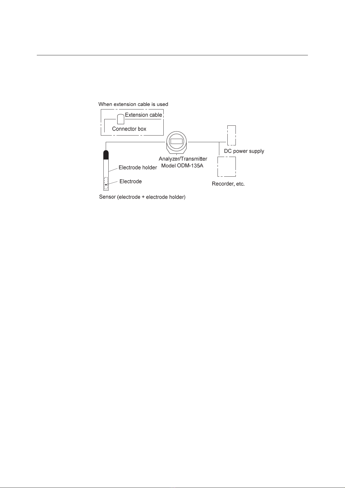
(a)Thank you for your purchase of our product. The Model ODM-135A Dissolved Oxygen
Analyzer/Transmitter (hereafter called the transmitter or the product) is a two-wire isolated type
indicating transmitter used in a measurement system for various processes to measure dissolved
Oxygen in liquid solutions.
Example of Measurement System
(b) Though the maximum available measuring range of DO is 0 to 50mg/L, one of nine (9) measuring
ranges is selectable according to your requirements. Usually, the measuring range is pre-set by
DKK-TOA before shipping in accordance with the specifications fixed when receiving your order.
The power supply must be 24VDC±10%. For other specifications, see 6.1 “Specifications”.
(c)Following displays are available though the output signal is delivered only with the DO measured
value.
・DO measured value display (unit: mg/L) Concentration of dissolved oxygen in water
・O2 measured value display (unit: %) Concentration of oxygen in the air
・SAT measured value display (unit: %) Saturation ratio of dissolved oxygen in water
・Solution temperature display (unit: °C) Temperature of in water
(d) The resistance value of the temperature compensation circuit to “compensate electrode
temperature characteristic” is 10kΩ/25°C (thermistor). Combine DO electrode whose temperature
compensation element is 10kΩtype.
(e)Since this manual mainly describes the transmitter, refer to the instruction manual attached to the
electrode or sensor for the sensor combined with the transmitter.
(f) An abnormal measured value may be indicated or output by the following causes. Build a system
such that related facilities are not damaged.
Any problem of the product such as deterioration or damage of the detecting section or
inappropriate insulation of cables.
Improper setting of operating conditions or calibration operation.
Electrical interference such as noise in the vicinity or improper grounding.
Other unpredictable phenomena

Model: ODM-135A Introduction
-
2
-
(g)Since important items are described in “Safety Information”, read the contents carefully.
(h)The product should be handled by persons who have received proper training. In addition, for
technical services such as repairs, ask a specialist to do who is qualified for the technical
certification system in our company or a person who has technical skills equivalent to that
certification system.
Model: ODM-135A Safety Information
-
3
-
Safety Information
(1) Meaning of markings
Meaning of signal terms and symbols used in notations of warning in the instruction manual is
described below. In addition, the alert symbol ( : General caution symbol) used on a product label,
etc. is meant to notify the existence of hazard/loss and it also means “Refer to the Instruction
Manual”.
:
Indicates the degree of hazard which can lead to death or serious injury if you fail to operate the
product properly.
Serious injury means an injury such as loss of sight, burns (high temperature or low temperature),
electric shock, bone fracture and poisoning, and the aftereffects of the injury remains or the injury
requires hospitalization or long periods of outpatient treatment.
:
Indicates the degree of hazard/loss which can result in injury or property damage if you fail to
operate the product properly.
Injury means an injury not requiring hospitalization or long periods of outpatient treatment and refers
to burns or electric shock. Property damage refers to widespread damage to the home, household
goods and livestock, pets, equipment, materials, etc. (damage to other than the product itself).
【IMPORTANT】Indicates important matters other than and . They are the
matters such as preventing damage to the product main body, preventing data
destruction, preventing wasting time, maintaining performance, and observing
regulations.
〔NOTE〕 Indicates comments, reasons, background information, a case example and other
items to help the reader understand the meaning.
>> Indicates reference items.
①, ②, ③Indicates item numbers such as the ones used in operations.
(2) Safety compliance items
Hazardous Gasses
Do not use the product in an area where explosive gas or flammable gas exists.
Using the product in any of these areas can cause explosion or fire.
Electric Shock
Do not touch the terminals inside the transmitter while power is applied. Touching
the terminals may cause electric shock.
The ground terminal must be grounded. If the terminal is not grounded and a
problem occurs in the power supply system, electric shock may result.

Model: ODM-135A Safety Information
-
4
-
Disassembly and Modification
Do not disassemble or modify the sections of the product that are not described in
the instruction manual. The product can be damaged.
Warning Label Lost
If any warning label affixed to this product becomes too difficult to read or lost,
please order a new one through your local sales agent or our sales office and affix it
to its original position.
(3) Notes on use of the instruction manual
Important items such as “Safety compliance items” are described in this manual. Handle the
manual as follows:
(a)The instruction manual is required not only at the start of operation but also required when
maintenance is performed or in case a failure occurs. Please keep the manual at hand all the time
so that the operator who actually operates the product can read the manual at any time.
(b)If the manual is lost or too smeared to read, please order a new copy through your local sales
agent or directly from our sales office.
(c)Some of the diagrams used in the manual or on product labels may be modified with part of their
shapes or displays omitted or they may be described in abstract form. In addition, numbers etc.
shown on the screen example are just examples for such cases.
(d)The contents of the manual may be changed without prior notice for reasons such as to improve
performance.
(e)Intellectual property right of the manual belongs to DKK-TOA. All or part of the manual must not
be reproduced without permission.

Model: ODM-135A Warranty
-
5
-
Warranty
(1) Warranty Coverage
DKK-TOA Corporation (DKK-TOA) warrants its products against defective material or workmanship for the warranty
period.
(a) The warranty period is one year from the date of delivery to the original user. If the date of delivery cannot be
specified, the warranty period is 24 months from the month following the date of manufacture shown on the
product nameplate.
(b) Specific written agreements with DKK-TOA, if any, shall take precedence over this warranty.
(c) The limitation of warranty described herein may not apply where applicable laws do not allow such limitation.
(2) Limited Warranty
This warranty does not cover the cases listed below.
(a) Direct or indirect failure or damage caused by the use of the product for a purpose or in a manner not prescribed by
the specifications or the instruction manual for the product.
(b) Direct or indirect failure or damage caused by force majeure, including but not limited to an act of God, natural
disaster such as earthquake, storm and flood damage, and lightning, fire, accident, abnormal voltage, salt damage,
gas damage, labor unrest, acts of war (declared or undeclared), terrorism, .civil strife, or acts of any governmental
jurisdiction.
(c) Failure or damage caused by any repair or modification not authorized by DKK-TOA.
(d) Failure or damage caused by the transport, moving, or dropping of the product after the purchase that is not
attributable to DKK-TOA.
(e) Electrodes and consumables (The warranty period for each part has priority when the period is shorter than that for
the main unit of the product. If the customer requires any part after more than six months from the date of
manufacture, consult DKK-TOA or its distributor.)
( f ) Failure or damage caused by the use of consumables, parts, or software not supplied by DKK-TOA.
(g) Malfunctions or damage caused by the use of connecting equipment not supplied by DKK-TOA.
(h) Loss of data, settings, programs, or software stored on the product not attributable to DKK-TOA.
( i ) Any product other than DKK-TOA’s, if specified by the purchaser or user, that incorporates, or is incorporated into
or combined with DKK-TOA’s products (*1). In such cases, this warranty covers DKK-TOA’s products only.
( j ) Any product not under proper maintenance in accordance with the instruction manual furnished by DKK-TOA.
(k) Products without a nameplate (excluding products proved to have been delivered by DKK-TOA).
EXCEPT AS EXPRESSLY SET FORTH IN THE PRECEDING SENTENCES, DKK-TOA MAKES NO
WARRANTY OF ANY KIND WHATSOEVER WITH RESPECT TO ANY PRODUCT. DKK-TOA EXPRESSLY
DISCLAIMS ANY WARANTY IMPLIED BY LAW, INCLUDING BUT NOT LIMITED TO ANY WARRANTY
OF MERCHANTABILITY OR FITNESS FOR A PARTICULAR PURPOSE.
LIMITATION OF REMEDIES: In the event that a defect is discovered within the warranty period, DKK-TOA or its
authorized distributor will, at its option, repair or replace the defective product or its part, or will refund the purchase
price of the product. THIS IS THE EXCLUSIVE REMEDY FOR ANY BREACH OF WARRANTY.
LIMITATION OF DAMAGES: IN NO EVENT SHALL DKK-TOA BE LIABLE FOR ANY INCIDENTAL OR
CONSEQUENTIAL DAMAGES OF ANY KIND FOR BREACH OF ANY WARRANTY, NEGLIGENCE, ON
THE BASIS OF STRICT LIABILITY, OR OTHERWISE.
(3) Others
(a) Product parts for maintenance (*2) will normally be supplied for five years (*3) from the date manufacturing and
sales are discontinued.
(b) The cause of any malfunction or damage shall be determined by a DKK-TOA technician.
(c) For repairs, contact a local distributor in your country or state.
*1: Warranties for products from other companies must be maintained by the user.
*2: Maintenance parts refers to parts that are required to maintain operation of the product.
*3: This five-year period is subject to availability of parts or their replacement.
Model: ODM-135A Reading Guide
-
6
-
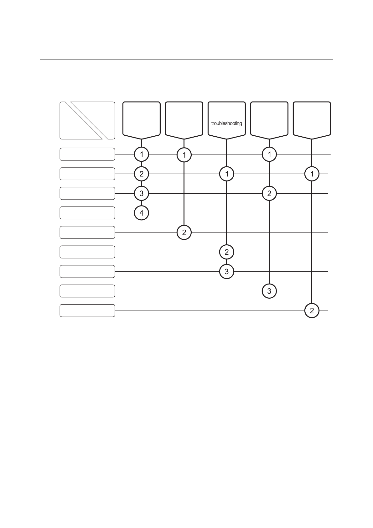
Reading Guide
Refer to the necessary sections of this instruction manual depending on your purposes such as
understanding the outline of this product or starting the product as shown below. The numbers in
circles indicate sections to be referred to in sequential order.
Purpose
Section
●Introduction
●Safety Information
1. Functions of Control
Section
2. Operation and
Calibration
3. Modes of Operations
4. Maintenance
5. Troubleshooting
6. Specifications and
Explanation
7. Installation
Start (start-up) Understand
the outline of
this product
Check
installation,
piping and
wiring
Perform
respective
operations
Maintenance
and inspection,
and

Model: ODM-135A Table of Contents
-
7
-
Table of Contents
●Introduction······················································································· 1
●Safety Information ········································································· 3
(1) Meaning of markings 3
(2) Safety compliance items 3
(3) Notes on use of the instruction manual 4
●Warranty ···························································································· 5
●Reading Guide ················································································ 6
1. Functions of Control Section ·······························
10
(1) Names of main components 10
(2) Switch functions 11
(3) Operation screen map 12
2. Operation and Calibration···································
13
2.1 Operation Start Procedure··································································
13
2.2 Calibration······················································································16
(1) Zero calibration with zero solution 16
(2) Zero calibration with input off 19
(3) Span calibration with air 20
(4) Span calibration with air saturated water 21
(5) Indication value in span calibration 22
2.3 Stopping Operation···········································································24
3. Modes of Operations ·········································
25
3.1 Measurement Mode Screen Selection ···················································
25
3.2 Maintenance Mode Calibration Screen Operation ····································
28
3.3 Operations of Setting Screen Group in Maintenance Mode ························
30
(1) Screen sequence of setting screen group 30
(2) DO value adjustment setting 33
(3) Liquid temperature shift setting 34
(4) Manual temperature compensation setting 35
(5) DO measuring range selection 37
(6) Membrane thickness selection 38
(7) Displayed item for calibration selection 39
(8) Stability check for calibration selection 40
(9) Signal amount for zero calibration and signal amount for span calibration setting 41

Model: ODM-135A Table of Contents
-
8
-
(10) Burnout selection 42
(11) Maintenance output type selection 44
(12) Transmission output response speed selection 46
(13) Applied voltage setting 47
(14) Measurement mode auto return selection 48
4. Maintenance····················································49
4.1 Maintenance List··············································································
49
4.2 Spare Parts·····················································································
50
4.3 Operation Check Using Equivalent Input ···············································
51
4.4 Transmission Output Adjustment ·························································
57
5. Troubleshooting ···············································
57
5.1 Error Message·················································································
57
(1) Error messages for calibration and necessary actions 57
(2) Other error messages and necessary actions 59
5.2 Troubleshooting Flowchart ·································································
60
6. Specifications and Explanation ····························
61
6.1 Specifications··················································································
61
6.2 Key Point of DO Measurement ····························································
64
(1) Important factors affecting the measurement 64
(2) Amount of saturated dissolved oxygen in water 66
(3) Measurement for samples containing salts 67
7. Installation ······················································
70
7.1 Transmitter Mounting ········································································
70
(1) Installation location of transmitter 70
(2) How to mount the transmitter 70
7.2 Sensor Mounting··············································································
71
7.3 Wire Connection ··············································································
72
(1) Wire connection diagram 72
(2) Electrode lead wires 72
(3) Power/transmission cable 73
(4) Grounding wire of transmitter 72
(5) Wire connection to transmitter 73
(6) Wire connection of “wash in progress” contact signal input cable (option) 76
(7) Wiring using conduit 77

Model: ODM-135A Table of Contents
-
9
-
7.4 Extension by Cable···········································································
78
(1) Extension cable 78
(2) Connector box 79
(Last page 80)

Model: ODM-135A 1. Functions of Control Section
-
10
-
1. Functions of Control Section
(1) Names of main components
Front cap
Case Rear cap
Bracket
Front cap Digital display
Calibration switch
Mode switch
Standby switch
()
()
Measure (MEAS) :Measure mode
Standby (ST-BY) :Maintenance mode
()
Appearance of Transmitter Front View
Digital Display
Model: ODM-135A 1. Functions of Control Section
-
11
-
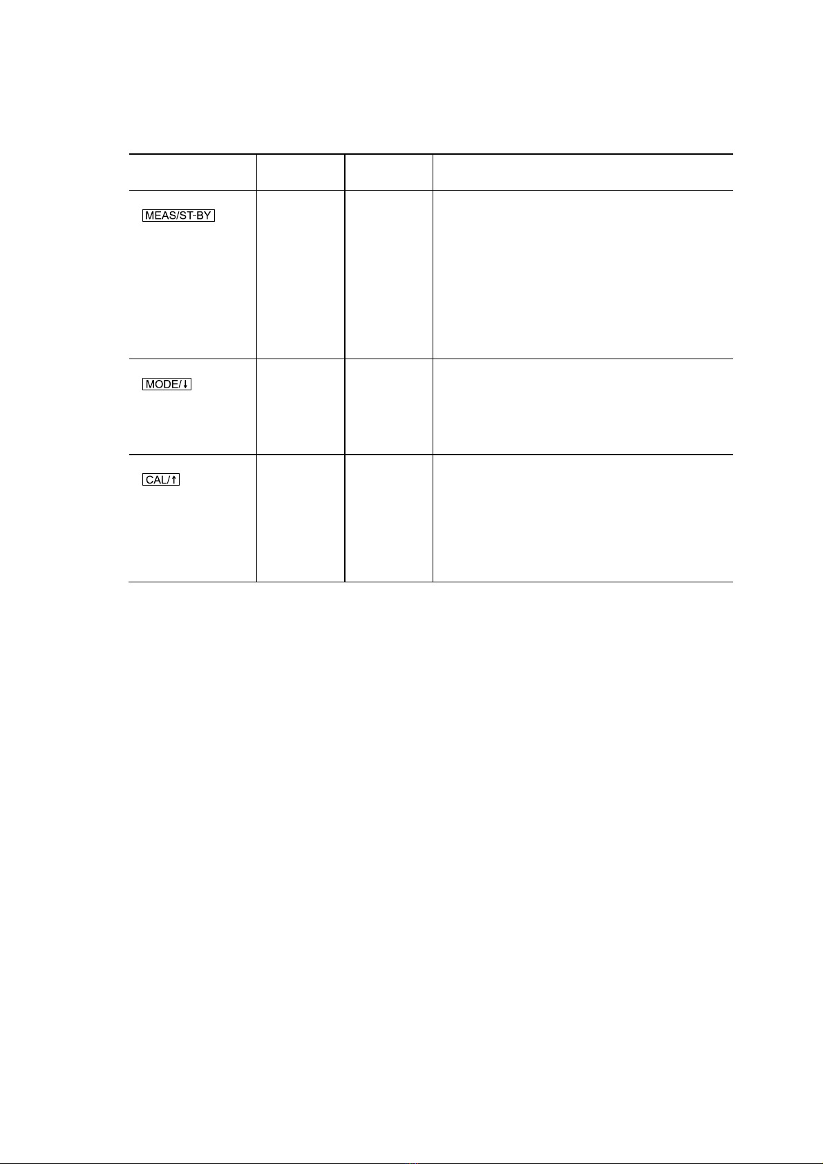
(2) Switch functions
Names and Functions of Switches
Name
(used in text)
Measurement
mode
Maintenance
mode Function
Standby switch
()
○○
When pressed for 3 seconds or more in the
measurement mode (Standby indicator “ST-BY” is
unlit), the mode changes to the maintenance mode
(“ST-BY” is lit).
When pressed for 3 seconds or more in the
maintenance mode, the mode returns to the
measurement mode.
When pressed once (less than 3 seconds) while the
transmitter is ready to select (or set) in the
maintenance mode, the set values will be
confirmed.
Mode switch
()
○○
Each time this switch is pressed once (less than 3
seconds) in the measurement mode or maintenance
mode, the screen switches from one to another.
When the transmitter is ready to change settings in
the maintenance mode, you can select the desired
setting item or decrease the setting value.
Calibration switch
()
○
Perform calibration in the maintenance mode
(Standby indicator “ST-BY” is lit).
Pressing this switch for 3 seconds or more in the
maintenance mode makes each item ready for
setting changes.
When the transmitter is ready to change settings in
the maintenance mode, you can select the desired
setting item or increase the setting value.
○: Enabled : Disabled

Model: ODM-135A 1. Functions of Control Section
-
12
-
(3) Operation screen map
〔 〕
(Power supply)
◎DO measured value screen (DO)
○Liquid temperature display screen (TEMP)
○Manual temperature compensation value
screen (M. TMP)
◎DO measuring range screen (RANG)
◎Membrane thickness screen (MEMB)
◎Displayed item for calibration screen
(CAL.S)
◎Zero calibration signal screen (ZERO)
◎Span calibration signal screen (SPAN)
○Burnout screen (B.OUT)
◎Transmission output type (S. OUT) screen
◎Transmission output response speed
screen (RESP)
◎Applied voltage screen (V.SET)
(To switch screen:)
〔Maintenance mode: “ST-BY”is lit〕
○Liquid temperature shift setting screen (TEMP etc.)
(Press this switch for
3 seconds or more)
(Press this switch for 3 seconds or more)
○DO value adjustment setting screen (D. ADJ etc.)
〔Setting screen group: “ST-BY”blinks〕
(Press this switch for
3 seconds or more)
◎DO measuring range selection screen (RANG)
◎Membrane thickness selection screen (MEMB)
◎Displayed item for calibration selection screen
(CAL.S)
◎Stability check for calibration selection screen
(STBL)
◎Zero calibration signal setting screen (ZERO)
◎Span calibration signal setting screen (SPAN)
◎Burnout selection screen (B.OUT)
◎Maintenance output type selection screen
(S.OUT)
(To switch screen:)
[Note] For “Transmission output adjustment”screen not included
here, refer to 4.4 “Transmission Output Adjustment”.
◎:Screens that appears always
○:Screens that may not appear depending on the settings or
by specifications
◎Applied voltage setting screen (V.SET)
◎Measurement mode auto return selection
screen (M.RET)
◎Transmission output response speed selection
screen (RESP)
◎O2 measured value screen (O2)
◎SAT measured value screen (SAT)
○Manual temperature compensation setting screen
(M.TEMP)
◎Calibration screen (D.CAL etc.)
Operation Screen Map

Model: ODM-135A 2.1 Operation Start Procedure
-
13
-
2. Operation and Calibration
2.1 Operation Start Procedure
The transmitter can be put into normal operating state by following each operation below.
①Check the installation condition. Check that the necessary installation work is completed,
which is described in 7. “Installation” (mounting, piping and wiring) and the installation related
items described in the instruction manual provided for the electrode or sensor.
②Prepare for the sensor. Perform the following preparation work for the sensor.
>> Instruction manual provided for the electrode or sensor
In the case of an immersion type Install the electrode to the sensor, remove the rubber cover,
and immerse the tip end of the electrode and so on.
In the case of a liquid flow-through type Install the electrode to the sensor, introduce sample
into the case of the sensor and so on.
In the case of a sensor with cleaner Other than above items, check the power supply of the
cleaner, etc.
【IMPORTANT】Combine DO electrode whose temperature element is 10kΩ/ 25ºC
(thermistor).
③Make sure of the power and turn it on. Make sure that the power to be supplied to the
transmitter is 24VAC ± 10% and then turn on the power.
【IMPORTANT】If the transmitter does not start normally when power is applied, turn off
power and wait for 10 seconds or more and then turn on power again.
Do not turn on power at least 10 seconds after power is turned off.
As soon as the power is supplied to the transmitter, the “DO measured value” screen, which is the
initial screen of the measurement mode (“ST-BY” is unlit), appears. The DO measured value is
displayed on the main display and the DO value adjustment amount is displayed on the sub
display. However, the DO value adjustment amount is not displayed when the value is zero.
(>> 3.3(2) “DO value adjustment setting”)
8.38
mg/L
DO
DO Measured Value Screen (DO)
Transmission output (4 to 20mA) is output 2 minutes after the power is turned on.
④Check the DO measuring range. Press several times until the “DO measuring
range” (RANG) screen appears and check the main display DO measuring range value.
Current DO measured
value
0.24(DO value adjustment amount)

Model: ODM-135A 2.1 Operation Start Procedure
-
14
-
Mode switch
( )
Calibration switch
( )
Standby switch
( )
Switches on the Underside of the Transmitter
10.00
mg/L
RA
N
G
DO Measuring Range Screen
Normally, the setting is made according to the ordered specification.
How to change the measuring range: >> 3.3(5) “DO measuring range selection”
⑤Set other items if necessary. If you find items specifically necessary among setting items
in the table below, set those values. However, “DO measuring range selection” in the table is
already checked in Step ④.
Example of 0.00 to
10.00mg/L
Model: ODM-135A 2.1 Operation Start Procedure
-
15
-
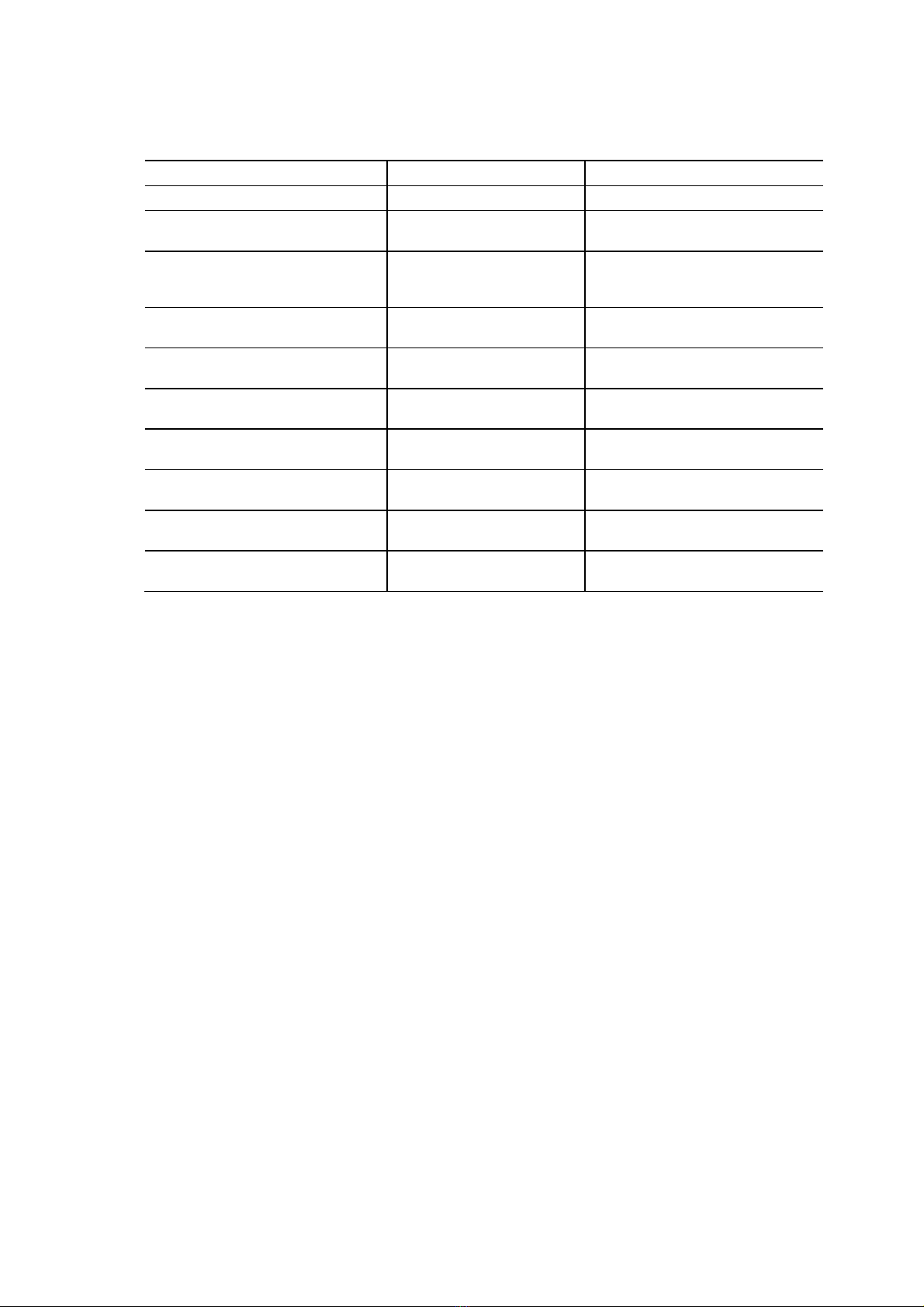
Factory Setting Values of Setting Items
Setting item Factory setting Reference item
DO value adjustment setting DO not adjusted (“oFF”) 3.3(2) “DO value adjustment setting”
Liquid temperature shift setting Liquid temperature not shifted
(“oFF”)
3.3(3) “Liquid temperature shift
setting”
Manual temperature compensation
setting
Manual temperature
compensation not performed
(“oFF”)
3.3(4) “Manual temperature
compensation setting”
DO measuring range selection Depends on the ordered
specifications
3.3(5) “DO measuring range
selection”
Displayed item for calibration
selection
do 3.3(7) “Displayed item for
calibration selection”
Stability check for calibration
selection
Stability check (“on”) 3.3(8) “Stability check for
calibration selection”
Burnout selection Burnout function not executed
(“oFF”)
3.3(10) “Burnout selection”
Maintenance output type selection Hold (“HoLd”) 3.3(11) “Maintenance output type
selection”
Transmission output response speed
selection
2 (standard) 3.3(12) “Transmission output
response speed selection”
Measurement mode auto return
selection
Automatically returns (“on”) 3.3(14) “Measurement mode auto
return selection”
⑥Perform the calibration. >> 2.2 “Calibration”
⑦Select the measurement mode screen. >> 3.1 “Measurement Mode Screen Selection”
The DO measurement system is now in normal operating state.

Model: ODM-135A 2.2 Calibration
-
16
-
2.2 Calibration
(a)Before measurement, this transmitter must always be calibrated and the characteristics of the
electrode and transmitter adjusted using standard solution.
(b)When measurements are continuous, the electrode characteristics are changed by contamination,
etc. of the sample water, but calibration prevents this effect. Periodically perform calibration even
after the start of operation.
(c)The calibration of the transmitter can start with either one of “Zero” or “Span” calibration first
(d)When “Calibration” (D.CAL etc.) screen is displayed, the transmitter automatically judges which
calibration is to be executed, “Zero” or “Span”, in response to the signal from the electrode. For
example, if the electrode is immersed in “Zero” reference solution, the transmitter automatically
goes into the state for zero calibration. And if the electrode is left in the air, the transmitter goes
into the state for span calibration.
(e)For the “Displayed Item for Calibration Selection” (CAL.S) screen in the setting mode, one of
“DO”, “O2” or “SAT” displayed item can be set for calibration. Factory setting is “DO”, but it can
be changed for calibration with “O2” or “SAT” according to the procedure.
(f) Calibration with air which is simple and accurate is also applicable for “Span” calibration.
(g)Execute “Zero” and “Span” calibration first before adjusting the indication of the transmitter to the
analysis data of the sample >> 3.3(2) “DO value adjustment setting”
(1) Zero calibration with zero solution
5 to 10% sodium sulfite solution is employed as “Zero” solution. >> “2.2(2) Zero calibration
with input off”
①Make preparations.
Extra pure anhydrous sodium sulfite (Na2SO3) 5 to 10g
Ion-exchanged water 1 to 2L
Beaker 1 (for zero calibration solution)
Beaker (large) 1 (for ion-exchanged water)
②Prepare zero solution. Fill one of the 2 beakers with 100mL of ion-exchanged water (to a
level sufficient for immersion of the electrode tip) and add 5 to 10g of anhydrous sodium sulfite
(approx. 2 spoonfuls) into it. Then, fill the other beaker with ion-exchanged water for rinsing the
electrode.
Ion-exchanged water
(for rinsing)
Beaker
Ion-exchanged
water (100mL)
Extra pure anhydrous sodium
sulfite (5 to 10g)
Zero
water
Zero Solution Preparations

Model: ODM-135A 2.2 Calibration
-
17
-
③Prepare the electrode. Prepare the electrode tip so that it can be immersed in the zero
solution prepared in the beaker. If the tip of the electrode is found dirty, thoroughly clean and rinse
it with ion-exchanged water.
④Set to maintenance mode. If the measurement mode (“ST-BY” unlit) is set, press
for 3 seconds or more.
The transmitter enters the maintenance mode (ST-BY). The “calibration” (D.CAL etc.) screen,
which is the initial screen of the maintenance mode, is displayed.
Mode switch
( )
Calibration switch
( )
Standby switch
( )
Switches on the Underside of the Transmitter
⑤Confirm the displayed item for calibration. Confirm that the sub display of
“Calibration” (D.CAL etc.) screen shows the displayed item with which the calibration is intended.
Sub display
D.CAL (DO displayed calibration) Calibration per concentration of dissolved oxygen in
water (mg/L)
O.CAL (O2displayed calibration) Calibration per concentration of oxygen (%)
S.CAL (SAT displayed calibration) Calibration per saturation ratio of dissolved oxygen in
water
Usually set the displayed item to D.CAL (DO displayed calibration) and change it if necessary.
>> 3.3(7) “Displayed item for calibration selection”
ST-BY
0.01
mg/L
D.CAL
ST-BY
0.1 %
O.CAL
ST-BY
0.1 %
S.CAL
Calibration Screen (D.CAL etc.)
Model: ODM-135A 2.2 Calibration
-
18
-
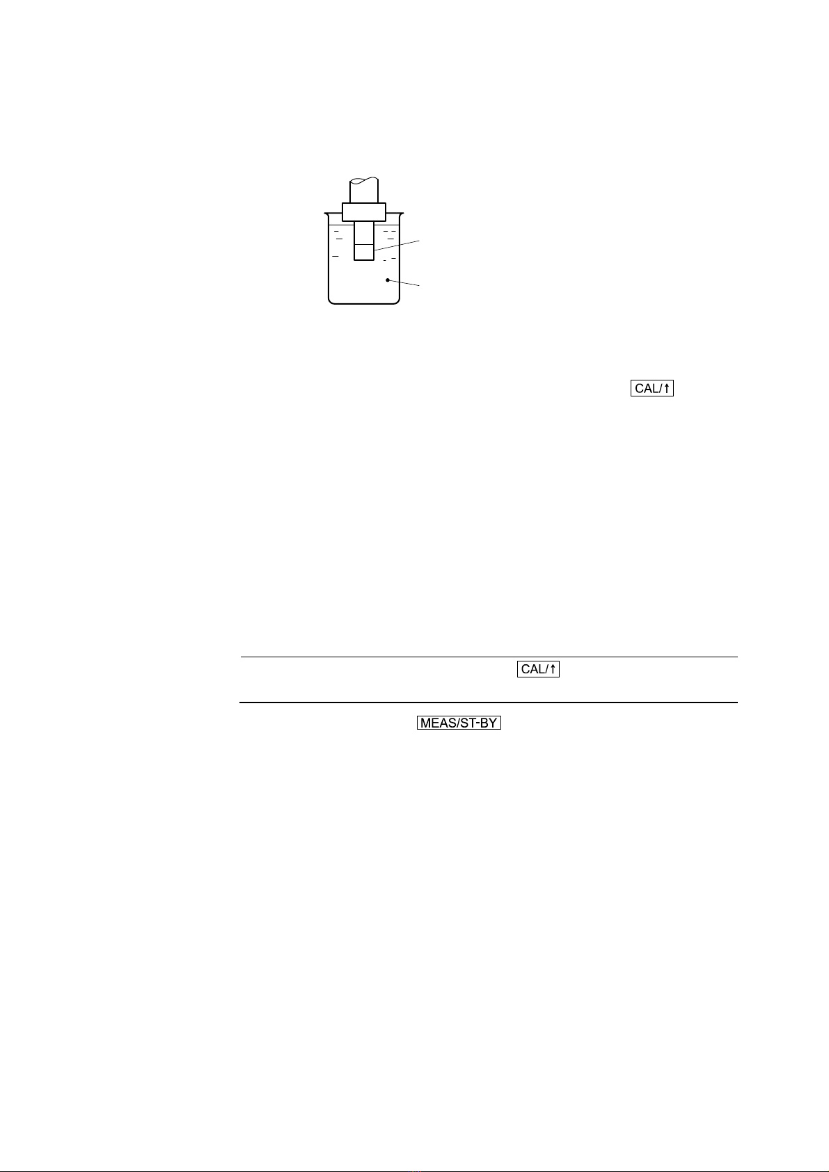
⑥Immerse the electrode into the zero solution. Rinse the electrode with ion-exchanged
water and immerse it into the prepared zero solution (sodium sulfite solution).
electrode
zero solution
(sodium sulfite solution)
Immersing Electrode into Zero Solution
⑦Start the zero calibration. Wait for about 30 to 60 minutes (1 to 2 hours for DO electrode
Model 7536L, 7546L) until the indication decreases and stabilizes. Then, press .
When wait display “WAIT” starts blinking, the zero calibration starts. When the zero calibration
is finished, “WAIT” goes out.
If “oFF” is set on “Stability check for calibration selection” (STBL) screen, the zero calibration
immediately starts without blinking “WAIT”. >> 3.3(8) “Stability check for calibration
selection”
Finally, “0.00mg/L” appears on the main display (in case of D.CAL) and the zero calibration
finishes.
If the zero calibration is required again, repeat the procedure from step ⑥.As for the span
calibration, refer to the related section described later.
⑧Set the sensor at the measuring point. Rinse the electrode with ion-exchanged water and
set the sensor at the measuring point.
【IMPORTANT】After the end of calibration, do not press in the calibration mode. If
it is pressed, calibration will become necessary.
⑨Set to measurement mode. Press for 3 seconds or more.
Return to the measurement mode (“ST-BY” unlit) and release transmission output hold.
Even if DO value adjustment is set to on, during calibration execution, DO value adjustment is
temporarily released and calibration is performed using the standard solution value. In addition,
when the transmitter is returned to the measurement mode after calibration is complete, the DO
value adjustment amount of the last time is displayed on the sub display and the measured value
contains that value.
Model: ODM-135A 2.2 Calibration
-
19
-
(2) Zero calibration with input off
This is a simplified method of zero calibration to be executed by disconnecting the electrode lead
wire from the terminal “1” of the transmitter, namely, by setting the input signal from the electrode
side to off (oFF) without using the zero solution.
Compared to the method mentioned in 2.2(1) “Zero calibration with zero solution”, although the
measured value tends to be higher by 0.02 to 0.04mg/L, this method may be convenient for the zero
calibration or zero point checking in a short time.
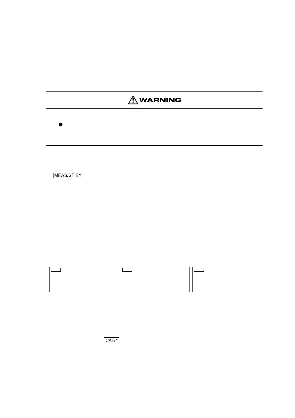
Electric Shock
If a “wash in progress” contact signal cable of sensor with cleaner (option) is
connected to the transmitter, do not touch the terminals in the product while power is
applied. An electric shock may result.
①Disconnect the electrode lead wire “1”. Remove the insulation cover in the transmitter
and disconnect the electrode lead wire from terminal “1”.
②Set to maintenance mode. If the measurement mode (“ST-BY” unlit) is set, press
for 3 seconds or more.
The transmitter enters the maintenance mode (ST-BY). The “calibration” (D.CAL etc.) screen,
which is the initial screen of the maintenance mode, is displayed.
③Confirm the displayed item for calibration. Confirm that the sub display of
“Calibration” (D.CAL etc.) screen shows the displayed item with which the calibration is intended.
Sub display
D.CAL (DO displayed calibration) Calibration per concentration of dissolved oxygen in
water (mg/L)
O.CAL (O2displayed calibration) Calibration per concentration of oxygen (%)
S.CAL (SAT displayed calibration) Calibration per saturation ratio of dissolved oxygen in
water
ST-BY
0.01
mg/L
D.CAL
<DO displayed calibration>
ST-BY
0.1 %
O.CAL
<O2displayed calibration>
ST-BY
0.1 %
S.CAL
<SAT displayed calibration>
Calibration Screen (D.CAL etc.)
Usually set the displayed item to D.CAL (DO displayed calibration) and change it if necessary.
>> 3.3(7) “Displayed item for calibration selection”
④Start the zero calibration. Wait for about 1 to 2 minutes until the indication decreases and
stabilizes. Then, press .
When wait display “WAIT” starts blinking, the zero calibration starts. When the zero calibration
is finished, “WAIT” goes out.
If “oFF” is set on “Stability check for calibration selection” (STBL) screen, the zero calibration
immediately starts without blinking “WAIT”. >> 3.3(8) “Stability check for calibration
selection”
Other TOA-DKK Measuring Instrument manuals


Popular Measuring Instrument manuals by other brands

Johnson Controls
Johnson Controls NAE-S installation guide

Rohde & Schwarz
Rohde & Schwarz HZ-14 operating manual

Licht
Licht MFC-200/N Technical manual

PCB Piezotronics
PCB Piezotronics IMI SENSORS 645B10 Installation and operating manual

Hobo
Hobo MicroRX Station RX2102 quick start

Vega
Vega VEGACAL 63 operating instructions


