TOA-DKK ALF-1600 User manual
Please keep this instruction manual close at hand of the persons who are in charge of
the operation of this product.
Before operating this product, please read this instruction manual carefully for its
correct handling.
ALKALINITY ANALYZER
MODEL ALF-1600
No. ALF-IB50604E

Model: ALF-1600 Introduction
-
1
-
Introduction
(a)Thank you for your purchase of the Model ALF-1600 Alkalinity Analyzer (hereinafter called the
analyzer or product). The analyzer measures the alkalinity of raw water for water supply and
purified water. It has two measurement systems; continuous and intermittent (batch measurement
at a minimum 1 hour interval).
Water receiving
tank and piping line
Alkalinity analyzer
(Model ALF-1600)
Receiving device
Example of Measuring System
(b)This product measures alkalinity by the neutralization titration method of coulometric titration.
(c)Depending on the order specifications, when measuring raw water for water supply and other dirty
high turbidity water, a water cleaning or ozone + water cleaning function that automatically cleans
the pipeline and flow cell are available as options.
(d)Depending on the option specifications, the following parts are supplied with the product;
(i) Water cleaning ⋅⋅⋅⋅⋅⋅⋅⋅⋅⋅⋅⋅⋅⋅⋅⋅⋅⋅ Solenoid valve (1), pressure reducing valve (1)
(ii) Ozone + water cleaning ⋅⋅⋅ Air pump, air filter, ozone generator, solenoid valve (2), and
pressure reducing valve (2)
(e)The measurement range is 0 to 50/100mg/L(or ppm). The 2 ranges are switched manually or
remotely. The units are set to mg/L or ppm by order specifications. Normally, the units cannot be
changed.
(f) The product may indicate or output an incorrect measured value due to the following reasons. We
recommend preparing a system such that the related facilities will not be damaged even in cases
like these.
•Any problem of the product such as deterioration or damage of the detecting section or
inappropriate insulation of cables.
•Improper setting of operating conditions or calibration operation.
•Electrical interference such as noise in the vicinity or improper grounding.
•Other unpredictable phenomena
(g)Since important items are described in “Safety Information”, read the contents carefully.
(h)The product should be handled by persons who have received proper training. In addition, for
technical services such as repairs, ask a specialist to do who is qualified for the technical
certification system in our company or a person who has technical skills equivalent to that
certification system.
Model: ALF-1600 Safety Information
-
2
-
Safety Information
(1) Meaning of markings
Meaning of signal terms and symbols used in notations of warning in the instruction manual is
described below. In addition, the alert symbol ( : General caution symbol) used on a product label,
etc. is meant to notify the existence of hazard/loss and it also means “Refer to the Instruction
Manual”.
:
Indicates the degree of hazard which can lead to death or serious injury if you fail to operate the
product properly.
Serious injury means an injury such as loss of sight, burns (high temperature or low temperature),
electric shock, bone fracture and poisoning, and the aftereffects of the injury remains or the injury
requires hospitalization or long periods of outpatient treatment.
:
Indicates the degree of hazard/loss which can result in injury or property damage if you fail to operate
the product properly.
Injury means an injury not requiring hospitalization or long periods of outpatient treatment and refers
to burns or electric shock. Property damage refers to widespread damage to the home, household
goods and livestock, pets, equipment, materials, etc. (damage to other than the product itself).
【IMPORTANT】Indicates important matters other than and . They are the
matters such as preventing damage to the product main body, preventing data
destruction, preventing wasting time, maintaining performance, and observing
regulations.
〔NOTE〕 Indicates comments, reasons, background information, a case example and other
items to help the reader understand the meaning.
>> Indicates reference items.
①, ②, ③Indicates item numbers such as the ones used in operations.
(2) Safety compliance items
Hazardous Gasses
Do not use the product in an area where explosive gas or flammable gas exists.
Using the product in any of these areas can cause explosion or fire.
Electric Shock
Do not touch the terminals inside the product while power is applied. Touching the
terminals may cause electric shock.
The ground terminal must be grounded. If the terminal is not grounded and a problem
occurs in the power supply system, electric shock may result.
Model: ALF-1600 Safety Information
-
3
-
Hazardous substances
Wear protective gear when handling the chemicals or the solutions which are
prepared based on it. Also always check the Material Safety Data Sheet (MSDS).
Disassembly and Modification
Do not disassemble or modify the sections of the product that are not described in
the instruction manual. The product can be damaged.
Warning Label Lost
If any warning label affixed to this product becomes too difficult to read or lost,
please order a new one through your local sales agent or our sales office and affix it
to its original position.
Disposal
In case you dispose of this product or any part of this product, handle it as industrial
waste as specified by law.
(3) Notes on use of the instruction manual
Important items such as “Safety compliance items” are described in this manual. Handle the manual
as follows:
(a)The instruction manual is required not only at the start of operation but also required when
maintenance is performed or in case a failure occurs. Please keep the manual at hand all the time so
that the operator who actually operates the product can read the manual at any time.
(b)If the manual is lost or too smeared to read, please order a new copy through your local sales agent
or directly from our sales office.
(c)Some of the diagrams used in the manual or on product labels may be modified with part of their
shapes or displays omitted or they may be described in abstract form. In addition, numbers etc.
shown on the screen example are just examples for such cases.
(d)The contents of the manual may be changed without prior notice for reasons such as to improve
performance.
(e)Intellectual property right of the manual belongs to DKK-TOA. All or part of the manual must not
be reproduced without permission.

Model: ALF-1600 Warranty
-
4
-
Warranty
(1) Warranty Coverage
DKK-TOA Corporation (DKK-TOA) warrants its products against defective material or workmanship for the warranty
period.
(a) The warranty period is one year from the date of delivery to the original user. If the date of delivery cannot be
specified, the warranty period is 24 months from the month following the date of manufacture shown on the
product nameplate.
(b) Specific written agreements with DKK-TOA, if any, shall take precedence over this warranty.
(c) The limitation of warranty described herein may not apply where applicable laws do not allow such limitation.
(2) Limited Warranty
This warranty does not cover the cases listed below.
(a) Direct or indirect failure or damage caused by the use of the product for a purpose or in a manner not prescribed by
the specifications or the instruction manual for the product.
(b) Direct or indirect failure or damage caused by force majeure, including but not limited to an act of God, natural
disaster such as earthquake, storm and flood damage, and lightning, fire, accident, abnormal voltage, salt damage,
gas damage, labor unrest, acts of war (declared or undeclared), terrorism, .civil strife, or acts of any governmental
jurisdiction.
(c) Failure or damage caused by any repair or modification not authorized by DKK-TOA.
(d) Failure or damage caused by the transport, moving, or dropping of the product after the purchase that is not
attributable to DKK-TOA.
(e) Electrodes and consumables (The warranty period for each part has priority when the period is shorter than that for
the main unit of the product. If the customer requires any part after more than six months from the date of
manufacture, consult DKK-TOA or its distributor.)
( f ) Failure or damage caused by the use of consumables, parts, or software not supplied by DKK-TOA.
(g) Malfunctions or damage caused by the use of connecting equipment not supplied by DKK-TOA.
(h) Loss of data, settings, programs, or software stored on the product not attributable to DKK-TOA.
( i ) Any product other than DKK-TOA’s, if specified by the purchaser or user, that incorporates, or is incorporated into
or combined with DKK-TOA’s products (*1). In such cases, this warranty covers DKK-TOA’s products only.
( j ) Any product not under proper maintenance in accordance with the instruction manual furnished by DKK-TOA.
(k) Products without a nameplate (excluding products proved to have been delivered by DKK-TOA).
EXCEPT AS EXPRESSLY SET FORTH IN THE PRECEDING SENTENCES, DKK-TOA MAKES NO
WARRANTY OF ANY KIND WHATSOEVER WITH RESPECT TO ANY PRODUCT. DKK-TOA EXPRESSLY
DISCLAIMS ANY WARANTY IMPLIED BY LAW, INCLUDING BUT NOT LIMITED TO ANY WARRANTY OF
MERCHANTABILITY OR FITNESS FOR A PARTICULAR PURPOSE.
LIMITATION OF REMEDIES: In the event that a defect is discovered within the warranty period, DKK-TOA or its
authorized distributor will, at its option, repair or replace the defective product or its part, or will refund the purchase
price of the product. THIS IS THE EXCLUSIVE REMEDY FOR ANY BREACH OF WARRANTY.
LIMITATION OF DAMAGES: IN NO EVENT SHALL DKK-TOA BE LIABLE FOR ANY INCIDENTAL OR
CONSEQUENTIAL DAMAGES OF ANY KIND FOR BREACH OF ANY WARRANTY, NEGLIGENCE, ON THE
BASIS OF STRICT LIABILITY, OR OTHERWISE.
(3) Others
(a) Product parts for maintenance (*2) will normally be supplied for five years (*3) from the date manufacturing and
sales are discontinued.
(b) The cause of any malfunction or damage shall be determined by a DKK-TOA technician.
(c) For repairs, contact a local distributor in your country or state.
*1: Warranties for products from other companies must be maintained by the user.
*2: Maintenance parts refers to parts that are required to maintain operation of the product.
*3: This five-year period is subject to availability of parts or their replacement.

Model: ALF-1600 Reading Guide
-
5
-
Reading Guide
Refer to the necessary sections of this instruction manual depending on your purposes such as
understanding the outline of this product or starting the product as shown below. The numbers in
circles indicate sections to be referred to in sequential order.

Model: ALF-1600 Table of Contents
-
6
-
Table of Contents
●Introduction·················································································································1
●Safety Information································································································2
(1) Meaning of markings ⋅⋅⋅ ⋅ 2
(2) Safety compliance items ⋅⋅⋅⋅ 2
(3) Notes on use of the instruction manual ⋅⋅⋅⋅ 3
●Warranty························································································································4
●Reading Guide ········································································································5
1. Composition·········································································································10
(1) Names ⋅⋅⋅⋅ 10
(2) Operation keys and screen display ⋅⋅⋅⋅ 12
2. Preparation for Operation·······································································14
2.1 Preparing the Reagent Solution ·············································································14
(1) Amount of reagent1L ⋅⋅⋅⋅ 14
(2) Amount of reagent 30L ⋅⋅⋅⋅ 15
2.2 Removing the Electrode Caps················································································17
2.3 Preparing the Calibration Solution Tank ································································18
3. Operation················································································································19
3.1 Starting Operation ···································································································19
3.2 Checking the Wash Operation················································································21
3.3 Stopping and Restarting Operation········································································23
(1) Stopping operation ⋅⋅⋅⋅ 23
(2) Restarting operation ⋅⋅⋅⋅ 23
4. Calibration ·············································································································24
4.1 Preparing the Calibration Solution ·········································································24
(1) Zero calibration solution ⋅⋅⋅⋅ 24
(2) Preparing the span calibration solution ⋅⋅⋅⋅ 24
4.2 Zero Calibration·······································································································25
4.3 Span Calibration ······································································································28
(1) Span calibration 1 ⋅⋅⋅⋅ 28

Model: ALF-1600 Table of Contents
-
7
-
(2) Span calibration 2 ⋅⋅⋅⋅ 31
4.4 Automatic Span Calibration ····················································································34
4.5 Calibration Solution Measurement ·········································································36
4.6 Flow Control·············································································································39
5. Modes of Operations···················································································41
5.1 Modes and Operation Map ·····················································································41
(1) Mode switching ⋅⋅⋅⋅ 41
(2) LCD high contrast ⋅⋅⋅⋅ 42
(3) Key lock ⋅⋅⋅⋅ 43
(4) Operation map ⋅⋅⋅⋅ 44
5.2 Measurement Mode Operation ···············································································45
5.3 Setting Mode Operation ··························································································48
(1) Measurement type ⋅⋅⋅⋅ 48
(2) Measurement mode remote switching ⋅⋅⋅⋅ 49
(3) Intermittent measurement interval ⋅⋅⋅⋅ 50
(4) Intermittent measurement start time ⋅⋅⋅⋅ 51
(5) Range switching type ⋅ ⋅⋅⋅ 52
(6) Range ⋅⋅⋅⋅ 53
(7) Alarm point ⋅⋅⋅⋅ 54
(8) Alarm band ⋅⋅⋅⋅ 55
(9) Wash interval ⋅⋅⋅⋅ 56
(10) Wash start time ⋅⋅⋅⋅ 59
(11) Wait time ⋅⋅⋅⋅ 60
(12) Calibration interval ⋅⋅⋅⋅ 61
(13) Calibration date ⋅⋅⋅⋅ 64
(14) Calibration start time ⋅⋅⋅⋅ 65
(15) Automatic calibrated value ⋅⋅⋅⋅ 66
(16) Stability check at automatic span calibration ⋅⋅⋅⋅ 67
(17) Response speed ⋅⋅⋅⋅ 68
(18) Output type ⋅⋅⋅⋅ 69
(19) Correction coefficient ⋅⋅⋅ ⋅ 71
(20) Flow target value ⋅⋅⋅⋅ 72
(21) Pump control ⋅⋅⋅⋅ 73
(22) Sampling pump ON/OFF ⋅⋅⋅⋅ 74
(23) Input signal ⋅⋅⋅⋅ 75
(24) Output signal ⋅⋅⋅⋅ 76
(25) LCD high contrast ⋅⋅⋅⋅ 77
5.4 Clock Adjustment ⋅⋅⋅⋅ 78

Model: ALF-1600 Table of Contents
-
8
-
6. Maintenance········································································································79
6.1 Maintenance List ·····································································································79
6.2 Accessories and Spare Parts ·················································································81
6.3 Removing the Electrodes························································································85
6.4 Cleaning the Glass Electrode·················································································87
6.5 Filling with the Reference Electrode Internal Solution··········································88
6.6 Replacing the Reference Electrode Ceramic ························································90
6.7 Cleaning the Electrolysis Electrodes ·····································································91
6.8 Replacing the Electrolysis Filter·············································································93
6.9 Cleaning the Flow Cell····························································································95
6.10 Replacing the Pump Tube·······················································································96
6.11 Regulating Tank Maintenance ···············································································100
6.12 Replacing the Solenoid Valves··············································································104
6.13 Replacing the Varistor Unit ····················································································106
7. Troubleshooting·······························································································108
7.1 Errors and Corrective Actions················································································108
7.2 Transmitter Troubleshooting ··················································································113
(1) Measured value error ⋅⋅⋅⋅ 113
(2) Measured value output error ⋅⋅ ⋅⋅ 114
(3) Concentration alarm output error ⋅⋅⋅⋅ 114
7.3 Detector Troubleshooting·······················································································115
7.4 Replacing the Fuse ································································································116
8. Specifications and Operational Explanation ························117
8.1 Specifications ·········································································································117
(1) Standard specifications ⋅⋅⋅⋅ 117
(2) Automatic wash ⋅⋅⋅⋅ 119
(3) Automatic calibration ⋅⋅⋅⋅ 120
8.2 Operational Explanation ························································································121
(1) Principle of measurement ⋅⋅⋅⋅ 121
(2) Measurement system of standard specifications ⋅⋅⋅⋅ 121
(3) Measurement system with wash ⋅⋅⋅⋅ 122
(4) Intermittent measurement ⋅⋅⋅⋅ 123
9. Installation ············································································································124
9.1 Installation···············································································································124
(1) Installation site ⋅⋅⋅⋅ 124

Model: ALF-1600 Table of Contents
-
9
-
(2) Outdoor installation and an installation in cold climates ⋅⋅⋅⋅ 124
(3) Installation particulars ⋅⋅⋅⋅ 124
9.2 Piping ······················································································································127
(1) Sample water piping ⋅⋅⋅⋅ 127
(2) Drain piping ⋅ ⋅⋅⋅ 127
(3) Wash water piping ⋅⋅⋅⋅ 127
9.3 Wiring ······················································································································128
(1) Cables used ⋅⋅⋅⋅ 128
(2) Wiring port ⋅⋅⋅⋅ 129
(3) Terminals ⋅⋅⋅⋅ 130
(Last page ⋅⋅⋅⋅ 132)
Model: ALF-1600 1. Composition
-
10
-
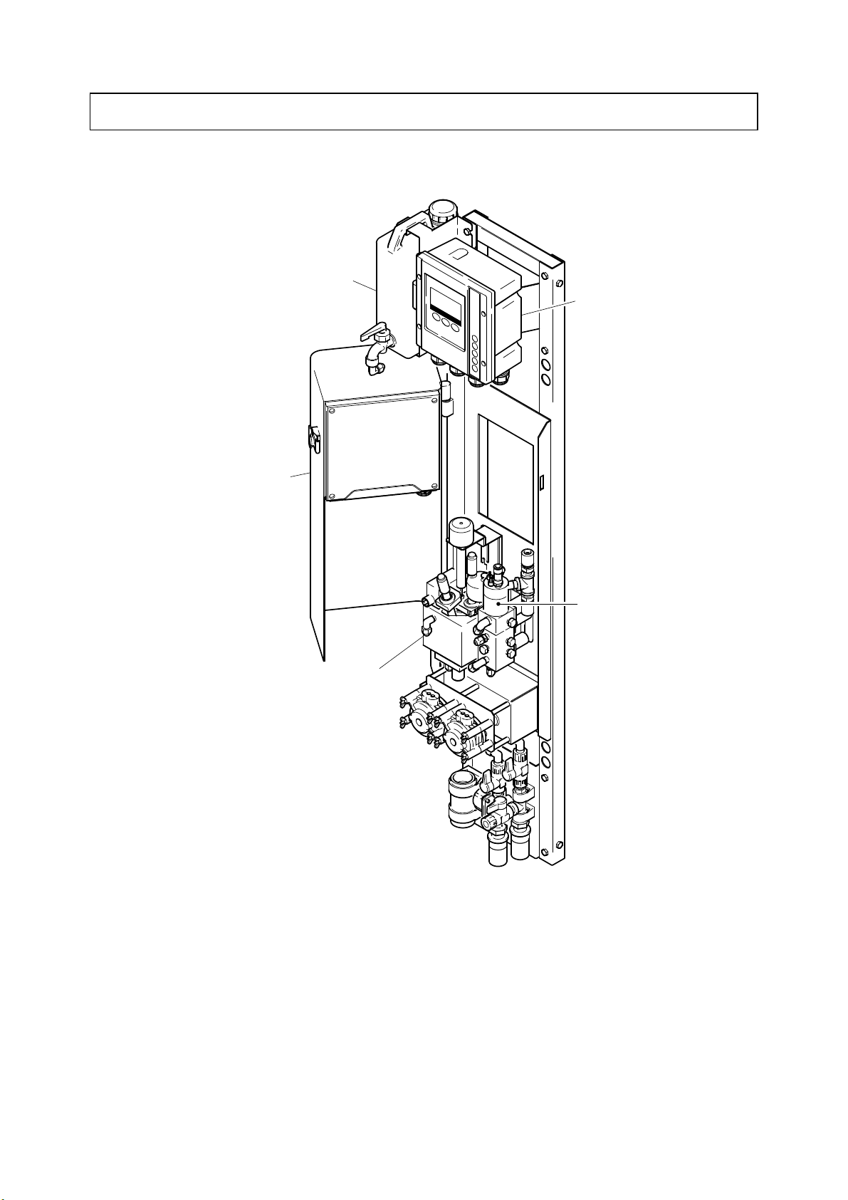
1. Composition
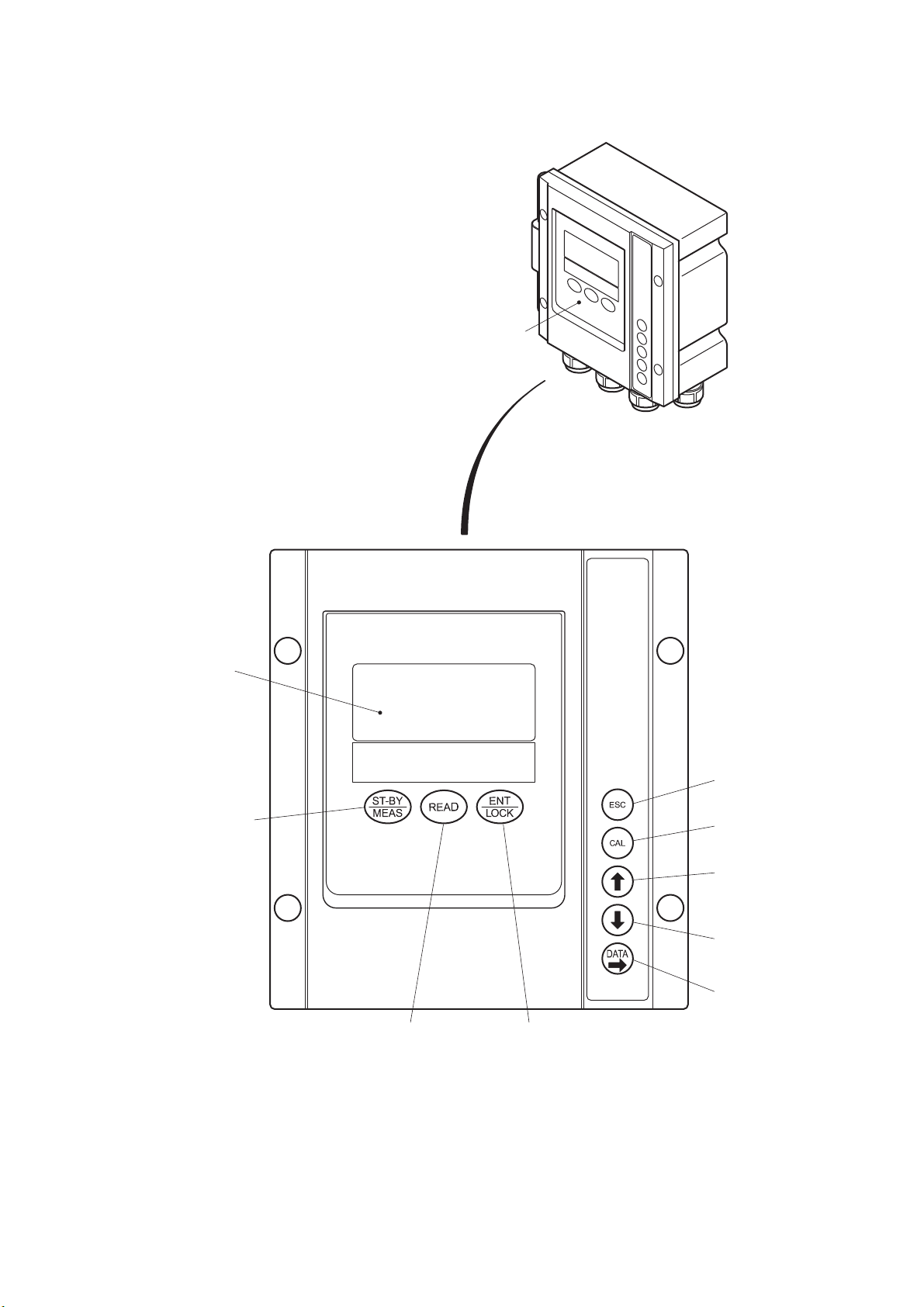
(1) Names
Calibration solution tank
Detection
section cover
Flow cell
Regulating tank
Transmitter
Standard Specifications
Model: ALF-1600 1. Composition
-
11
-
Operation panel
Display panel
Standby key
Enter/Lock key
Escape key
Calibration key
Up key
Down key
Data key
Read key
Transmitter

Model: ALF-1600 1. Composition
-
12
-
(2) Operation keys and screen display
Operation Key Functions
Operation key (Notation in the text) Function
Measure/Standby key
( )
•Switches to the maintenance mode when this key is pressed for 4
seconds or more in the measurement mode.
•Returns to the measurement mode when this key is pressed for 4
seconds or more in the maintenance mode.
Read key
( )
•Displays the parameters at the bottom of the screen (bottom
display).
•The parameters are not displayed when is pressed after
parameters display.
Enter/Lock key
( )
•Confirms the number or symbol that was input and simultaneously
switches to the next screen.
•The operation keys are locked when this key is pressed for 4
seconds or more in the measurement mode.
The keys are released when this key is pressed for 4 seconds or
more in the locked state.
Escape key
( )
•Returns to the state before operation.
•Cancels input.
•Cancel during operation is possible when this key is pressed for 4
seconds or more during calibration.
Calibration key
( )
•Switches to the calibration mode when this key is pressed in the
maintenance mode. Returns to the maintenance mode when
is pressed.
Up key
( )
•Sequentially displays each parameter when is pressed and
the parameters are displayed at the bottom of the screen in the
measurement mode.
•Sequentially displays each parameter when pressed after switching
to the setting mode by pressing in the maintenance
mode.
•Sequentially displays each calibration operation when pressed after
switching to the calibration mode by pressing in the
maintenance mode.
•Increments the number or switches the alternative when pressed at
number setting in the setting mode and calibration mode.
Down key
( )
•Sequentially displays each parameter when is pressed and
the parameters are displayed at the bottom of the screen in the
measurement mode. (Displayed in the reverse order of the Up key.)
•Sequentially displays each parameter when pressed after switching
to the setting mode by pressing in the maintenance
mode. (Displayed in the reverse order of the Up key.)
•Sequentially displays each calibration operation when pressed after
switching to the calibration mode by pressing in the
maintenance mode. (Displayed in the reverse order of the Up key.)
•Decrements the number or switches the alternative when pressed at
number setting in the setting mode and calibration mode.
Data key
( )
•Switches to the setting mode and displays “PARAMETER” on the
screen when pressed in the maintenance mode. Returns to the
maintenance mode when is pressed.
•Moves “digit” of the number to the right when pressed at setting
mode value setting.

Model: ALF-1600 1. Composition
-
13
-
〔NOTE〕•About modes and screen groups ⋅⋅⋅ >> 5.1(1) “Mode switching”
•About screen composition and switching ⋅⋅⋅ >> 5.1(4) “Operation map”
LCD high contrast display
Error display
Measurement item display
High alarm display
Low alarm display
Model No. display
Bottom display
Key Lock display
Time display
Mode display
Measured value display
Unit display
Calibration solution display
Flow control display
Screen Display
Kinds of Displays
Display Function
Measured value display •Displays the measured value mainly in the measurement mode and
setting mode.
•Blinks when the measured value has exceeded measuring range 2.
Bottom display •Displays the parameters at the bottom of the display in the
measurement mode and setting mode.
Unit display •Displays the unit of the value shown on the main display.
Mode display MEAS •“MEAS” is displayed when the analyzer is in the measurement
mode.
ST-BY •“ST-BY” is displayed when the analyzer is in the maintenance
mode.
PARAM •“PARAM” is displayed when the analyzer is in the setting mode.
CAL •CAL is displayed when the analyzer is in the calibration mode.
Model No. display
•Displays the model No. of the analyzer.
Measurement item display
•Displays the item to be measured and the measurement system.
“ALK(CONT)” ⋅⋅⋅ Alkalinity (continuous measurement)
“ALK(ITMC)” ⋅⋅⋅ Alkalinity (intermittent measurement)
Alarm displays (high, low)
•Display “H”, “L” when the measured value has exceeded the set
alarm value.
Error display •Error display is displayed when an error was generated at the
analyzer. >> 7 “Troubleshooting”
Flow control display •Displays “FLOW” when the flow is being controlled.
Time display •Displays the current time.
Key lock display •Displays key lock icon when other key functions are stopped.
Calibration solution display •Blinks when the calibration solution is being measured.
LCD high contrast display •Displays LCD high contrast icon when the LED indicator is
displayed in the maximum contrast.
>> 5.1(2) “LCD high contrast”

Model: ALF-1600 2.1 Preparing the Reagent Solution
-
14
-
2. Preparation for Operation
2.1 Preparing the Reagent Solution
Hazardous substances
Wear protective gear when handling the Extra pure grade anhydrous sodium sulfate
used for preparing the reagent. Also always check the Material Safety Data Sheet
(MSDS).
(1) Amount of reagent 1L
【IMPORTANT】•Decide the amount of reagent to be prepared by taking into account the
measurement interval (for intermittent measurement), reagent solution
consumption, and similar factors.
•Normally, the preparation criterion is the amount used in 1 month.
•When 1 month has elapsed from the preparation date, prepare a new
reagent solution even if there is reagent solution remaining.
The reagent solution consumption is generally as follows:
Continuous measurement: Approx. 720mL/day, Approx. 22L/month
Intermittent measurement 1 hour interval ⇒Approx. 540mL/day, Approx. 16L/month
3 hour interval ⇒Approx. 420mL/day, Approx. 13L/month
①Ready the regent. ⋅⋅⋅⋅⋅⋅ Ready the following reagent as a 1L portion of the reagent preparation
amount.
・Extra pure grade anhydrous sodium sulfate: 25g
②Prepare the regent. ⋅⋅⋅⋅⋅⋅ Prepare the reagent by the following procedure and pour it into the
reagent tank (hereinafter referred to as tank A).
Put about 900mL of ion exchange water in a beaker or similar container.
While stirring the liquid with a stirrer, gradually add and dissolve the reagent of step ①.
【IMPORTANT】•Add the solid reagent after breaking it up by shaking the container
vigorously beforehand. If the reagent is solid, it will take a long time for it
to dissolve.
After checking that the reagent has dissolved, re-stir the entire amount as 1L.
Pour the reagent solution into the reagent tank.
③Remove the cover. ⋅⋅⋅⋅⋅⋅ Remove the cover of tank A by the following procedure:
Place a clean plastic container (bucket, etc.) near the side of the analyzer.
Loosen the white hexagon cap nut of tank A, and remove the cover.
Rinse the cover with ion exchange water and place it into the container of step .

Model: ALF-1600 2.1 Preparing the Reagent Solution
-
15
-
【IMPORTANT】•A float switch and suction tube are attached to the cover. Do not get them
dirty.
④Wash the tank A. ⋅⋅⋅⋅⋅⋅ Discard the reagent remaining in tank A and wash tank A with ion
exchange water.
⑤Pour the regent solution into tank A. ⋅⋅⋅⋅⋅⋅ Pour the reagent solution of step ②into tank A.
⑥Install the cover. ⋅⋅⋅⋅⋅⋅ Check that the suction tube is not bent, and install the cover of tank A.
(2) Amount of reagent 30L
①Ready the regent. ⋅⋅⋅⋅⋅⋅ Ready the following reagent as a 30L portion of the reagent preparation
amount.
•Extra pure grade anhydrous sodium sulfate: 750g
②Remove the cover. ⋅⋅⋅⋅⋅⋅ >> Step ③of 2.1(1)
③Wash the tank A. ⋅⋅⋅⋅⋅⋅ >> Step ④of 2.1(1)
④Prepare the regent. ⋅⋅⋅⋅⋅⋅ Prepare the reagent by the following procedure.
Fill tank A with ion exchange water to about 90% (about 27L) of its capacity.
Gradually add the reagent of step ①while stirring it with a stirring rod, etc.
【IMPORTANT】•Add the solid reagent after breaking it up by shaking the container
vigorously beforehand. If the reagent is solid, it will take a long time for it
to dissolve.
After checking that the entire reagent has dissolved completely, re-stir the entire amount as
30L.
【IMPORTANT】•Always stir.
•Add the reagent gradually while confirming that it has dissolved. If a large
amount of reagent is added at one time, it will solidify in tank A and will be
difficult to dissolve.
〔NOTE〕•A Model MX5 stirrer (option) can also be used to stir the reagent.
<How to use>
Set the MX5 at the cover mounting mouth of tank A containing the reagent and ion
exchange water.
→Supply power and thoroughly stir the solution with the electric arm.
→Dissolving is complete in about 15 to 30 minutes.
•However, always add at the reagent gradually at this time also.
•The reagent usually dissolves in 15 to 30 minutes, but may take more than 30 minutes
when the water temperature is low. When the water temperature is extremely low, fill the
tank with the ion exchange water beforehand so that the water temperature rises up to
normal temperature.
⑤Install the cover. ⋅⋅⋅⋅⋅⋅ Check that the suction tube is not bent, and install the cover of tank A.

Model: ALF-1600 2.1 Preparing the Reagent Solution
-
16
-
【IMPORTANT】•When reagent was prepared, always perform zero and span calibration.
>> 4. “Calibration”.
•When changing the reagent solution, turn off the analyzer power or place
the analyzer into the maintenance mode.
•We recommend that a spare tank A be provided. The replacement time
can be shortened by preparing the reagent in the spare tank A and
replacing the cover of empty tank A.
〔NOTE〕•When changing the reagent, to accelerate reagent replacement inside the analyzer, the
reagent can be fed at high speed by operating the pump at high speed. We recommend
about 5 minutes high speed operation.
>> 5.3(21) “Pump control”
•If preparing 30L at one time is difficult, prepare the reagent in 5 to 10L batches and use it
to replenish the reagent tank.
Model: ALF-1600 2.2 Removing the Electrode Caps
-
17
-
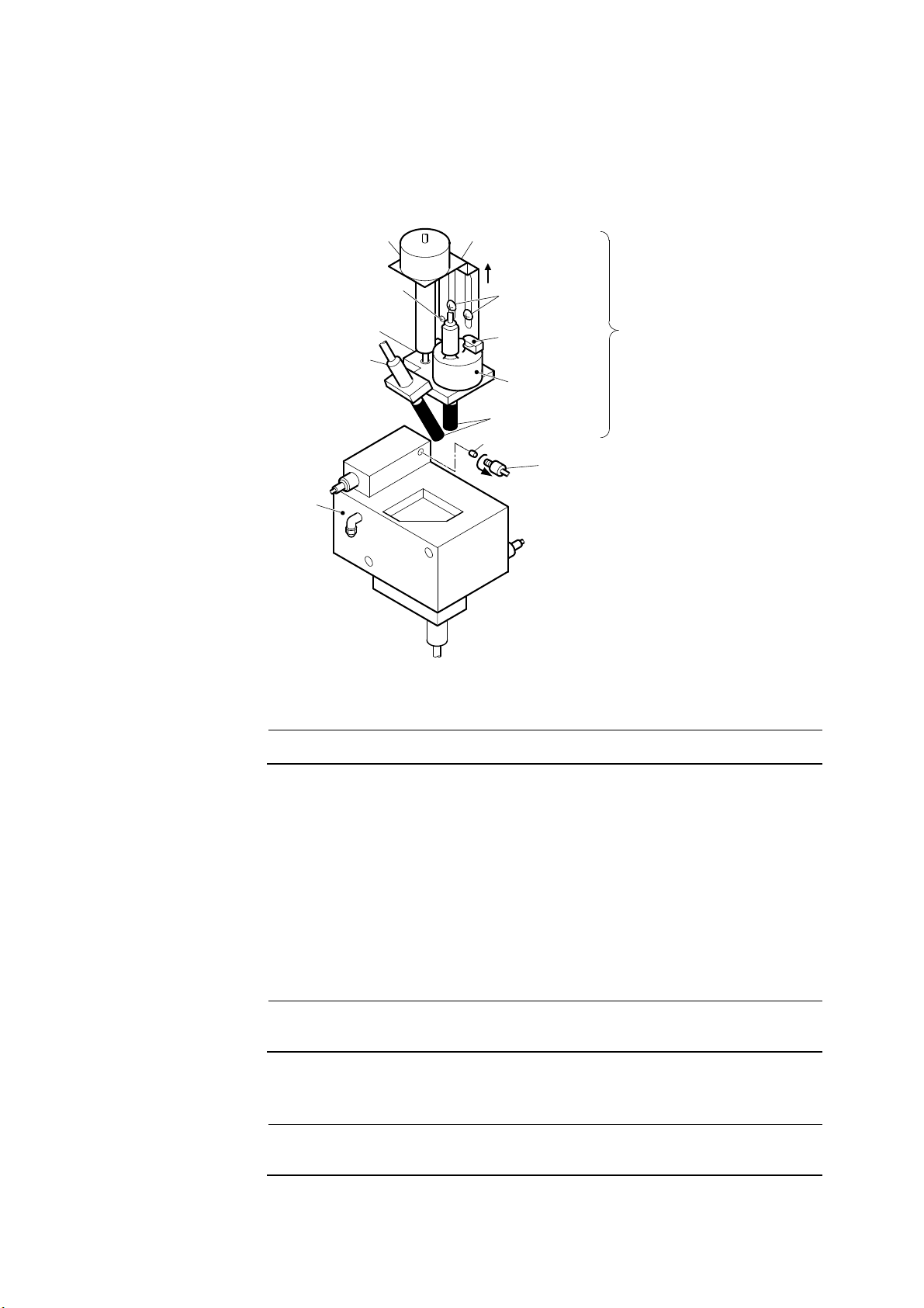
2.2 Removing the Electrode Caps
To prevent damage during transportation, a rubber cap is attached to the glass electrode and
reference electrode. Remove these caps by the following procedure:
Flow cell
Fixing plate
Screw A
(2 places)
(Pull up)
Stir motor
Screw B
Reference
electrode
Glass electrode
Sleeve
Joint A
Electrode section
Rubber cap
Rubber cap
(Internal solution
filling port)
Electrode holder
Removing the Electrode Caps
【IMPORTANT】•Since the glass electrode breaks easily, handle it with care.
①Disconnect the piping. ⋅⋅⋅⋅⋅⋅ Loosen flow cell joint A (including the sleeve) and hexagon cap nut,
and disconnect the piping.
②Raise the electrode section. ⋅⋅⋅⋅⋅⋅ Loosen screws A (2 places), B and raise the electrode section.
After raising the electrode section, fix it by tightening screws A and B.
〔NOTE〕•Two electrodes, a stirrer, and an electrode holder are fixed to the fixing plate. Collectively
they are called the electrode section.
③Remove the rubber caps. ⋅⋅⋅⋅⋅⋅ Remove the rubber caps at the end of the glass electrode, the
reference electrode and at the internal solution filling port.
【IMPORTANT】•Check that the electrodes are not damaged and that there is sufficient
internal solution in the reference electrode.
④Return to original state. ⋅⋅⋅⋅⋅⋅ Return the electrode section and piping to their original state by
the opposite procedure of steps ①and ②.
【IMPORTANT】•Do not damage the end of the electrodes by striking it against the flow
cell.

Model: ALF-1600 2.3 Preparing the Calibration Solution Tank
-
18
-
2.3 Preparing the Calibration Solution Tank
Before starting operation, connect the empty calibration solution tank (hereinafter referred to as
tank B) to the analyzer. Before performing manual calibration, fill tank B with zero or span
calibration solution.
>> 4.1 “Preparing the Calibration Solution”
①Install the tank B. ⋅⋅⋅⋅⋅⋅ Install empty tank B to the frame.
Tank knob
Calibration solution tank
(Tank B)
Valve BV3
(for calibration solution)
Transmitter
"Open" "Close"
Preparing the Calibration Solution Tank (Tank B)
②Connect the tube. ⋅⋅⋅⋅⋅⋅ Connect the tube (for calibration solution) to valve BV3 (for calibration
solution) of tank B.
③Check the valve BV3. ⋅⋅⋅⋅⋅⋅ Check that valve BV3 is closed.

Model: ALF-1600 3.1 Starting Operation
-
19
-
3. Operation
3.1 Starting Operation
①Check the installation work. ⋅⋅⋅⋅⋅⋅ Make sure that the installation work (installation, piping,
wiring and power) is completed. >> 8.1 “Specifications”, 9. “Installation”, “Specification for
delivery”
②Make the operation preparations. ⋅⋅⋅⋅⋅⋅ Perform the following work or make sure that
preparations have been completed.
•2.1 “Preparing the Reagent Solution”
•2.2 “Removing the Electrode Caps”
•2.3 “Preparing the Calibration Solution Tank”
【IMPORTANT】•Make sure that valve BV1 (for sample water) and valve BV2 (for sampling
port) are closed. If the valves are open and passing water, the sample
water will spout from the open-to-air port at the top of the regulating tank
and from BV2 and the analyzer may be damaged.
③Pass the sample water. ⋅⋅⋅⋅⋅⋅ Gradually open valve BV1.
【IMPORTANT】•After flow adjustment, make sure that the sample water is overflowing
from the regulating tank. At this time be sure that the sample water is not
overflowing from the open-to-air port of the regulating tank.
〔NOTE〕•If the sample water is not overflowing from the regulating tank, there is probably air in
the piping or the sample water pressure is low. Remove the air or check the sample water
conditions. >> 8.1 “Specifications”
Passing the Sample Water
④Turn on the power. ⋅⋅⋅⋅⋅⋅ Turn on the transmitter power switches in the following order:
•Bottom switch → Top switch
•After the screens are sequentially switched, the analyzer enters the measurement mode.
Table of contents
Other TOA-DKK Measuring Instrument manuals


Popular Measuring Instrument manuals by other brands

National Instruments
National Instruments NI 435 Series user manual

Mark-10
Mark-10 M2-20 user guide

Chadwick-Helmuth
Chadwick-Helmuth Vibrex 2000 Plus user guide

Boonton
Boonton 1121A instruction manual

Endress+Hauser
Endress+Hauser Cleanfit W CPA450 operating instructions

Tempo Communications
Tempo Communications OFL100 quick reference


horiba
horiba 5002S-10C instruction manual

KLINGER
KLINGER PS116 Operation manual

DENT Instruments
DENT Instruments ELITEpro ELOG 15 quick start guide

E+E Elektronik
E+E Elektronik EE671 user manual

Onicon
Onicon System-10 BTU Meter installation guide

Endress+Hauser
Endress+Hauser Liquistation CSF33 operating instructions