OfiTE 900 User manual

Model 900 Viscometer
130-76-C (115 Volt)
130-76-1-C (230 Volt)
ORCADA®Model 900 Software
Instruction Manual
Updated 1/4/2017
Ver. 14.0
Patent No. 6,766,028 - OFI Testing Equipment, Inc.
OFI Testing Equipment, Inc.
11302 Steeplecrest Dr. · Houston, Texas · 77065 · U.S.A.
Tele: 832.320.7300 · Fax: 713.880.9886 · www.ote.com
©Copyright OFITE 2015

Patent No. 6,766,028 - OFI Testing Equipment, Inc.
OFITE, 11302 Steeplecrest Dr., Houston, TX 77065 USA / Tel: 832-320-7300 / Fax: 713-880-9886 / www.ote.com 1
Introduction.....................................................................................2
Description......................................................................................2
Components ...................................................................................3
Specications .................................................................................4
Safety...............................................................................................7
Setup................................................................................................8
Software Start ...............................................................................10
Calibration.....................................................................................14
Standalone................................................................................14
With Computer ..........................................................................16
Fluid Manager ...........................................................................18
Operation.......................................................................................19
Standalone................................................................................19
With Computer ..........................................................................23
Software ........................................................................................25
Options......................................................................................25
Save Rate Settings ...................................................................26
Test Builder ...............................................................................27
Select Analysis Outputs ............................................................30
Saved Test Data........................................................................31
Calibration History.....................................................................33
Import/Export ............................................................................34
Onboard Program Manager ......................................................35
Upload Test Data ......................................................................37
Disassembly .................................................................................39
Maintenance..................................................................................39
Bob Shaft Bearing Replacement...............................................40
Main Shaft Bearing Replacement .............................................44
Torsion Spring Replacement.....................................................46
Appendix .......................................................................................47
Thermocouple Calibration.........................................................47
Adjusting the P Value................................................................49
Transducer Linearization...........................................................50
Driver Install ..............................................................................53
Grounding .................................................................................56
Warranty and Return Policy ........................................................57
Table of
Contents

Patent No. 6,766,028 - OFI Testing Equipment, Inc.
OFITE, 11302 Steeplecrest Dr., Houston, TX 77065 USA / Tel: 832-320-7300 / Fax: 713-880-9886 / www.ote.com 2
The Model 900 Viscometer is a portable, yet fully automated system
for measuring uid viscosity. It is designed to be easy to use, easy to
maintain and to provide consistent results. Its simplicity makes it ideally
suited for eld applications. Engineers will appreciate the push button
calibration, its reliability, and the ability to perform standard American
Petroleum Institute (API) recommended practices with one command.
With the addition of a computer, it is able to perform a variety of more
complex laboratory tests. Routine repairs, like bearing and torsion spring
replacement, may be performed by eld personnel with a minimum of
training, without having to return the viscometer for repair. The optional
*KlikLock™ bob uses a magnetic coupling to make removal quick and easy.
The OFITE Model 900 Viscometer is a true Couette coaxial cylinder rotational
viscometer, which employs a transducer to measure the induced angle of
rotation of the bob by a uid sample. The test uid is contained in the annular
space, or shear gap, between the rotor and the bob, which is attached to
a shaft with a biasing spring. The viscous drag exerted by the uid creates
a torque on the bob, and is monitored by the transducer that measures
the angular displacement of the bob. Using the angle of displacement
of the bob, the processor calculates and transmits readable output of
the sample characteristics in accordance with determined calculations
based upon the shear rate and the bob displacement. Revolutionary
improvements in stepper-motor technology by OFITE enables the Model 900
Viscometer to operate accurately at extremely low shear rates (0.01 1/s).
As a stand-alone eld unit, the press of a single button (MUD or CEM)
prompts the viscometer to perform standard API recommended practices for
the technician’s choice of Mud (Plastic Viscosity [“PV”] - Yield Point [“YP”]) or
Cement rheologies. Standard speeds (600, 300, 200, etc.) are provided as
single button operations on the keypad, or if another shear rate is desired, the
parameters may be entered on the numbered keypad. Simply press ENTER
after entering the desired shear rate and the viscometer performs the rest
of the work. It is not necessary to stop the motor between speed changes.
For a fully automated Control/Data Acquisition System suitable for
research applications, the Model 900 Viscometer may be connected
to a computer via a serial (RS-232) port using OFITE’s exclusive
and eld-proven Windows™-based ORCADA® software.
*U.S. Patent Number 8,763,776
Introduction
Description

Patent No. 6,766,028 - OFI Testing Equipment, Inc.
OFITE, 11302 Steeplecrest Dr., Houston, TX 77065 USA / Tel: 832-320-7300 / Fax: 713-880-9886 / www.ote.com 3
#130-76-03 Thermocouple
#130-76-04 Main Bearing
#130-76-05 Retaining Ring
#130-76-08 Bob Shaft Wrench
#130-76-10 Universal Heat Cup (115 Volt Only)
#130-76-10-1 Universal Heat Cup (230 Volt Only)
#130-76-24 Bob Shaft Assembly (For Threaded Bobs)
#130-76-241 Bob Shaft Assembly (For KlikLock™ Bobs)
#130-76-51 Carrying Case
#130-79-19 USB to RS232 Cable
#132-56 Rotor, R1, 303 Stainless Steel
#132-57 Bearing Shield
#132-58 Bob, Threaded, B1, 303 Stainless Steel
#132-58-01 Bob, KlikLock™, B1, 316 Stainless Steel
#132-80 Certied Calibration Fluid, 100 cP, 10 oz
#134-05-2 Bob Shaft Bearing, Sealed
#134-10 Torsion Spring Assembly, F1.0
#135-02 External Retainer Ring for Bob Shaft
#152-37 AC Power Cord, 115 Volt
#152-38 AC Power Cord, 230 Volt
Optional:
#130-76-LSK Low Shear Kit
#132-56-S Rotor, R1, Slotted
#132-58-5 Bob, B1, Slotted
#134-05-2 Bob Shaft Bearing
#134-10-2 Torsion Spring Assembly, F0.2
#147-14 pH Meter
#132-56H Rotor, R1, Hastelloy
#132-58-01H Bob, Threaded, B1, C-276 Hastelloy
#132-58-01-HC Bob, KlikLock™, B1, C-276 Hastelloy
#134-10-2 Torsion Spring Assembly, F0.2 (Green)
#134-10-3 Torsion Spring Assembly, F0.5 (Yellow)
#134-10 Torsion Spring Assembly, F1.0 (Blue)
#134-10-4 Torsion Spring Assembly, F2.0 (Red)
#134-10-5 Torsion Spring Assembly, F3.0 (Purple)
#134-10-6 Torsion Spring Assembly, F4.0 (White)
#154-04 Digital, Long-Stem Thermometer, NIST Traceable, 8"
Stem, -58°F - 302°F (-50°C - 150°C)
#154-24 Thermometer, 32°F - 86°F (0°C - 30°C)
#130-76-C-SP Spare Parts Kit for #130-76-C
#130-76-03 Thermocouple
#130-76-04 Main Bearing, Qty: 2
#130-76-05 Retaining Ring, Qty: 2
#132-80 Calibration Fluid, 100 cP, 16 oz
#132-81 Calibration Fluid, 50 cP, 16 oz
#134-05-2 Bob Shaft Bearing, Qty: 8
#135-02 External Retainer Ring, Qty: 2
Components

Patent No. 6,766,028 - OFI Testing Equipment, Inc.
OFITE, 11302 Steeplecrest Dr., Houston, TX 77065 USA / Tel: 832-320-7300 / Fax: 713-880-9886 / www.ote.com 4
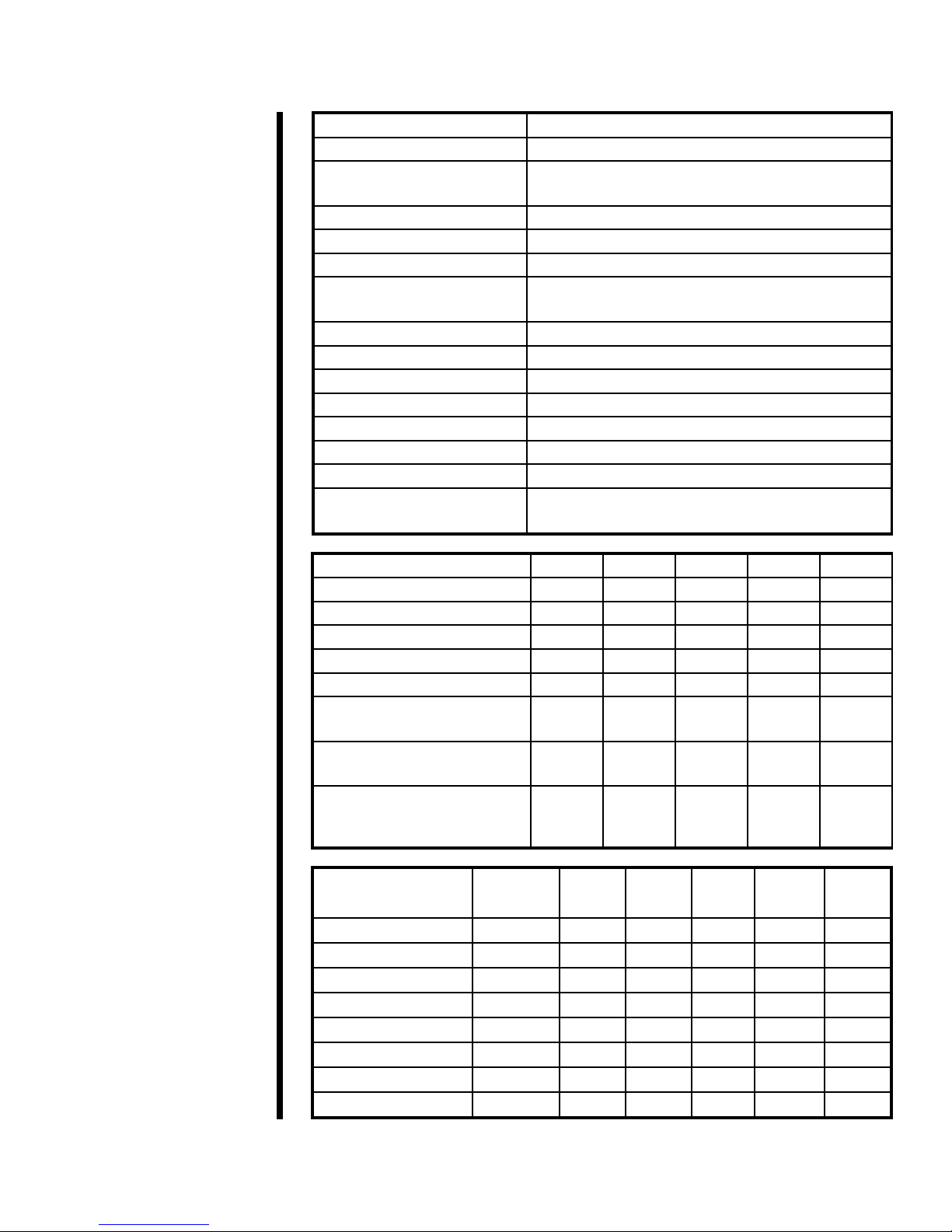
Specications Instrument Geometry True Couette Coaxial Cylinder
Motor Technology Stepper
Motor Speeds (RPM) 12 Fixed Speeds (600, 300, 200, 100, 60, 30, 20,
10, 6, 3, 2, and 1); Variable speed range .006 - 1000
Speed Accuracy (RPM) .001
Shear Rate Range (sec-1).01 - 1,700
Readout Digital
Heat Cup Stainless Steel, 150 Watts, Maximum
Recommended Temp: 190°F (88°C)
Temperature Measurement Type “J” Thermocouple
Automatic Tests API Cementing and Mud Rheologies
Power Requirements 97 - 250 Volts AC, 200 Watts, 50/60 Hz
Weight (kg) 8.6
Dimensions (cm) 44 × 38 × 24
Shipping Weight (kg) 16
Shipping Dimensions (cm) 56 × 38 × 24
Computer Requirements DB-9 Serial Port, Windows 2000 or newer.
Recommended screen resolution 1024 × 768 pixels.
Rotor - Bob R1B1 R1B2 R1B3 R1B4 R1B5
Rotor Radius, RR, (cm) 1.8415 1.8415 1.8415 1.8415 1.8415
Bob Radius, RB, (cm) 1.7245 1.2276 0.8622 0.8622 1.5987
Bob Height, L, (cm) 3.8 3.8 3.8 1.9 3.8
Shear Gap, (cm) 0.117 0.6139 0.9793 0.9793 0.2428
R Ratio, RB/RR 0.9365 0.666 0.468 0.468 0.8681
Shear Rate Constant kR(sec-1
per RPM) 1.7023 0.377 0.2682 0.2682 0.8503
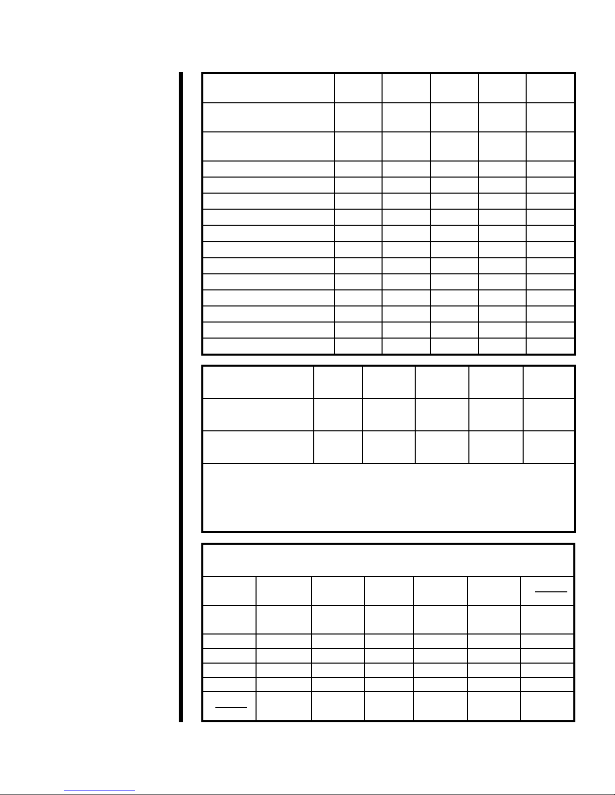
Shear Stress Constant for
Effective Bob Surface kS(cm-3)0.01323 0.02610 0.05290 0.10600 0.01541
Overall Instrument Constant,
K, with Standard F1.0 Spring,
ŋ=KfƟ/N
300 2,672 7,620 15,200 349
Max. Shear Stress,
SSMAX, (Dyne / cm2)
Constant
kT
R1B1 R1B2 R1B3 R1B4 R1B5
F 0.2 (Green) 77.2 330 651 1,320 2,644 384
F 0.5 (Yellow) 193 840 1,657 3,359 6,730 977
F 1.0 (Blue) 386 1,680 3,314 6,717 13,460 1,955
F 2.0 (Red) 772 3,360 6,629 13,435 26,921 3,910
F 3.0 (Purple) 1,158 5,040 9,943 20,152 40,381 5,865
F 4.0 (White) 1,544 6,720 13,257 26,870 53,841 7,819
F 5.0 (Black) 1,930 840 16,571 33,587 67,302 9,774
F 10.0 (Orange) 3,860 16,800 33,143 67,175 134,603 19,548

Patent No. 6,766,028 - OFI Testing Equipment, Inc.
OFITE, 11302 Steeplecrest Dr., Houston, TX 77065 USA / Tel: 832-320-7300 / Fax: 713-880-9886 / www.ote.com 5
Shear Rate Range R1B1 R1B2 R1B3 R1B4 R1B5
Shear Rate Constant, KR,
(sec-1 per RPM) 1.7023 0.3770 0.2682 0.2682 0.8503
Shear Rate, (sec-1 or 1/s)
1 RPM 1.70 0.38 0.27 0.27 0.85
2 RPM 3.40 0.75 0.54 0.54 1.70
3 RPM 5.11 1.13 0.80 0.80 2.56
6 RPM 10.21 2.26 1.61 1.61 5.11
10 RPM 17.02 3.77 2.68 2.68 8.51
20 RPM 34.05 7.54 5.36 5.36 17.03
30 RPM 51.07 11.31 8.05 8.05 25.54
60 RPM 102.14 22.62 16.09 16.09 51.07
100 RPM 170.23 37.70 26.82 26.82 85.12
200 RPM 340.46 75.40 53.64 53.64 170.23
300 RPM 510.69 113.10 80.46 80.46 255.35
600 RPM 1,021.38 226.20 160.92 160.92 510.69
1,000 RPM 1,702.30 377.00 268.20 268.20 851.15
Viscosity Ranges<a>
(cP) R1B1 R1B2 R1B3 R1B4 R1B5
Minimum Viscosity<b>
@600 RPM 0.5<c> 4.5 12.7 25 1.2
Maximum Viscosity<d>
@0.01 RPM 10,000,000 89,000,000 255,000,000 500,000,000 23,000,000
<a> Computed for standard Torsion Spring (F 1.0). For other torsion 160.92springs, multiply by F factor
<b> Lower viscosities can be measured by the Model 900, however one must take into account the
effect of bearing drag, Taylor vortices, zero offset, etc. when looking at the expected accuracy of
the reading
<c> For practical purposes the minimum viscosity is limited to 0.5 cP due to Taylor Vortices
<d> Maximum viscosity is based on Maximum Shear Stress and Minimum shear rate (RPM). However,
due to practical and physical limitations, it may be difcult to take these measurements.
Viscosity Conversions
To convert from units on left side to units on top, multiply by factor @ intercept.
Centipoise
(cP) Poise (P) g/(cm*s) (mN*s)m2mPa*s (lb*s)
100 ft2
Centipoise
(cP) 10.01 0.01 1 1 0.002088
Poise (P) 100 1 100 100 100 0.2088
g/(cm*s) 100 1 100 100 100 0.2088
(mN*s)m210.01 0.01 1 1 0.002088
mPa*s 1 0.01 0.01 1 1 0.002088
(lb*s)
100 ft2478.93 4.789 4.789 478.93 478.93 1

Patent No. 6,766,028 - OFI Testing Equipment, Inc.
OFITE, 11302 Steeplecrest Dr., Houston, TX 77065 USA / Tel: 832-320-7300 / Fax: 713-880-9886 / www.ote.com 6
Shear Stress Conversions
To convert from units on left side to units on top, multiply by factor @ intercept.
Dyne/cm2Pa lb/100ft2lb/ft2DR
Dyne/cm210.1 0.2084 0.002084 0.1957
Pa 10 1 2.084 0.02084 1.957
lb/100ft24.788 0.4788 10.01 0.939
lb/ft2478.8 47.88 100 1 93.9
DR 5.107 0.5107 1.065 0.01065 1
What Bob & Spring Should I Use?
There is often confusion or misunderstanding about what a viscometer can
actually measure. For example, a viscometer with an R1B1 F1 combination
can measure water fairly well at 100 RPM and higher, but at 3 RPM, the
readings would be shaky at best. While on the other hand, a linear uid with a
viscosity of 15000, could not get past 6 RPM with the same combination.
To estimate which spring might be best, use the formula below to calculate a
Minimum Spring factor, where one establishes the maximum RPM the uid is
going to be tested at, as well as what the expected “Apparent Viscosity” of the
uid at that RPM. If the Factor comes out as .87, then an F 1.0 spring should
be used. If it comes out as .16, then an F 0.2 spring would be best. To cover
all ranges, it may be necessary to use more than one spring.
Always run the TransCal procedure (steps 10 - 14 on page 51) after
changing the bob or spring.
Minimum Spring Factor (F) = RPM(max) * AV(max)
BOB(F)*90000
Bob (F)
R1B1 1.0
R1B2 8.9
R1B3 25.4
R1B4 50.7
R1B5 2.4

Patent No. 6,766,028 - OFI Testing Equipment, Inc.
OFITE, 11302 Steeplecrest Dr., Houston, TX 77065 USA / Tel: 832-320-7300 / Fax: 713-880-9886 / www.ote.com 7
Safety In order to comply with the requirements of safety standard EN 61010, the
viscometer has a separable cord and plug, without a locking device, to mate
with a socket outlet in the building. If the user substitutes another cord, the
cord should not exceed 3 meters (9'10") in length.
Any interruption of the protective earth conductor inside or outside the
instrument, or disconnection of the protective earth terminal is likely to
make the instrument dangerous under some fault conditions. Intentional
interruption is prohibited.
If the equipment is used in a manner not specied by the manufacturer,
the protection provided by the equipment might be impaired. Whenever it
is likely that protection has been impaired, the instrument should be made
inoperative, and secured against accidental operation. OFITE Technical
Service should be contacted for advice.
Any service performed by removing the viscometer cover should only be
performed by a knowledgeable operator.
There are no user-serviceable components inside the heat cup cover. The
Heat Cup should only be serviced by a factory-authorized technician.

Patent No. 6,766,028 - OFI Testing Equipment, Inc.
OFITE, 11302 Steeplecrest Dr., Houston, TX 77065 USA / Tel: 832-320-7300 / Fax: 713-880-9886 / www.ote.com 8
Setup The Model 900 Viscometer is a precision instrument. Any damage to the bob
shaft, bearings, or transducer will greatly affect the accuracy of the readings.
Always handle the Viscometer with care, especially when installing and
removing the bob.
1. To install the bob, rst slide the bearing shield (#132-57) onto the bob
shaft with the at portion facing up. Locate the wrench ats on the bob
shaft. Place the bob shaft wrench (#130-76-08) against these ats to hold
the shaft in place. Tighten the bob by turning it clockwise (when viewed
from above).
Always use the bob shaft wrench when installing or removing the
bob. Do not tighten the bob against the stop pin.
If the bob or spring is being changed, run the TransCal procedure (steps
10 – 14 on page 51).
Bob Shaft Wrench
(#130-76-08)
Bearing Shield
(#132-57)
2. Some viscometers are equipped with a magnetic KlikLock™ bob. To
install this bob, slide it up into the rotor and turn it just until it clicks into
place.
3. Connect the instrument to a power source. This viscometer will operate
equally well at 115 Volts or 230 Volts, 50 or 60 Hz.
Always plug the Model 900 into a surge suppressor instead of
directly into an electrical outlet. The internal electrical components
can be damaged by voltage spikes.
4. To control the temperature, plug the thermocouple into the left side of the
housing cover and place the thermocouple into the thermocouple well of
the heat cup. Also plug the power cord of the heat cup into the back of
the Model 900. Turn the knob on the heat cup all the way to maximum to
allow the viscometer to control the temperature.

Patent No. 6,766,028 - OFI Testing Equipment, Inc.
OFITE, 11302 Steeplecrest Dr., Houston, TX 77065 USA / Tel: 832-320-7300 / Fax: 713-880-9886 / www.ote.com 9
6. The On-Off switch is located on the back panel, just above the power
cable connection. Turn the unit on and follow the display instructions, or
press CLEAR/STOP.
7. Refer to the “Thermocouple Calibration” section on page 47.
It is recommended that a calibration procedure be run due to
the possibility of mishandling during shipment of the Model 900.
Refer to the “Calibration - Standalone” section on page 14
for instructions on calibrating the unit manually. Refer to the
“Calibration - With Computer” section on page 16 for instructions
on calibrating the unit with the ORCADA®Software.
8. Place a properly prepared sample of test uid (if an R1B1 bob is being
used, approximately 165 - 170 mL) in the sample cup and immerse
the rotor exactly to the scribed line on the rotor by raising the platform.
Tighten the lock nut on the platform.
9. When operating under computer control, the keypad on the Model 900
unit is disabled and the unit is controlled from the PC. However, the type
of bob being used for the test must be entered in SETUP (refer to step 5
on page 19 for details) before connecting the unit to the PC
5. Position the rotor sleeve over the bob and move it upwards to join the
rotor. The threads assure the rotor sleeve will attach evenly and uniformly
each and every time.
Rotor Sleeve
Bob
Rotor

Patent No. 6,766,028 - OFI Testing Equipment, Inc.
OFITE, 11302 Steeplecrest Dr., Houston, TX 77065 USA / Tel: 832-320-7300 / Fax: 713-880-9886 / www.ote.com 10
The OFITE Model 900 Viscometer can be operated from a PC using the
ORCADA® Model 900 software. When operating under computer control, the
keypad on the Model 900 is disabled and all operation is controlled from the
PC.
If your computer does not have a DB-9 serial port, but does have a USB
port, it is recommended that you purchase a USB to Serial converter that
uses the FTDI chipset. OFITE part number 130-79-19 is one such converter,
but others are available. It is critical that any converter used has the FTDI
chipset. Using a converter without the FTDI chipset could result in poor
communication, erroneous results, or even damage to your machine.
The computer must be running Windows® 2000 or newer. For optimum
viewing, it is recommended that your computer’s display be set to 1024 x 768
pixel resolution.
1. Double-click the “ORCADA®” icon on the desktop.
2. The rst time you run the software, you will be asked to select a hardware
conguration. Select the the appropriate device and click “OK”. You will
now see the Main Screen.
3. The Windows XP rewall may try to block the ORCADA® software from
communicating with the viscometer. If the rewall shows the following
alert, select “Unblock”.
Software Start
Windows XP Firewall Alert
Available Tests Log Indicator Status Communication
Indicator
Manual Mode
Controls
Analysis Data Process Variables
Key

Patent No. 6,766,028 - OFI Testing Equipment, Inc.
OFITE, 11302 Steeplecrest Dr., Houston, TX 77065 USA / Tel: 832-320-7300 / Fax: 713-880-9886 / www.ote.com 11
“Start Test” - This button starts a test in Auto Mode. Once a test is started,
this button becomes the “Abort Test” button. Click here to stop the test.
“Cement” - This button performs the same function as the “CEM” button on
the unit’s keypad. Refer to page 21 for more information.
“Mud” - This button performs the same function as the “MUD” button on the
unit’s keypad. Refer to page 21 for more information.
The “Mud” and “Cement” buttons perform standard tests based
on API specications. These tests ignore the “Dead Time” and
“DAQ Time” settings on the Options screen. Temperature control, which
is disabled during custom Auto-Mode tests, is available during a “Mud” or
“Cement” test.
“Progress” - This button opens the Test Progress window, which shows all of
the steps of the current test and highlights the one currently in process.
“Status” - This box at the top of the screen shows the current status of the
test.
“Comm Timeout” - This light will be off when the PC is successfully
communicating with the viscometer. If communication is interrupted for any
reason, the light will shine red to indicate a problem.
“Start Logging” - This button is available in manual mode only. Click here to
begin recording test data. The light next to this button will shine green while
logging is in progress.

Patent No. 6,766,028 - OFI Testing Equipment, Inc.
OFITE, 11302 Steeplecrest Dr., Houston, TX 77065 USA / Tel: 832-320-7300 / Fax: 713-880-9886 / www.ote.com 12
“Cond Pause” - This button will pause a test during the conditioning phase
and put the software into Manual Mode. While the test is paused, the motor
and heat controls can be controlled in the same manner as in a standard
Manual Mode test.
To resume the test, click the “Cond Pause” button again. You will be asked if
you want to “Continue” the test with the remaining conditioning time or if you
want to “Override” the remaining time and extend the effective conditioning
time. If you choose to “Continue”, the time remaining in the conditioning
cycle will appear as though the test was never paused. If you choose to
“Override”, the time remaining in the conditioning cycle will resume at the
point where the test was paused.
For example, assume a test has a conditioning time of 10 minutes and the
test is paused at the 5 minute mark for 1 minute. If the test is unpaused
using the “Continue” option, the time remaining in the conditioning cycle will
be 4 minutes. However, if the test is unpaused using the “Override” option,
the time remaining in the conditioning cycle will be ve minutes, making the
effective total conditioning time 11 minutes.
“Raw File Save Period” - This eld determines how often data is recorded
during a test.
“Experiment Name” - This eld will be used to identify the experiment later.
This eld is required before starting a test in Auto Mode or starting logging in
Manual Mode.
“Bob” - Select the type of bob currently being used in the unit. An incorrect
value in this eld will adversely affect your test results.
“Key” - The checkboxes next to the graph key enable and disable graphing
of the indicated values. For example, to exclude RPM from the graph,
uncheck the “RPM” box. You can also customize the appearance of the lines
on the graph by clicking on the line example on the right side of the key.
“Manual Mode Controls” - The manual mode controls, in the bottom left-
hand corner or the screen, adjust the rotor speed and the temperature while
the unit is operating in manual mode.
“Rotation” - This eld determines the rotational speed. The drop-down
box beneath the eld sets the units to either RPM or 1/s.

Patent No. 6,766,028 - OFI Testing Equipment, Inc.
OFITE, 11302 Steeplecrest Dr., Houston, TX 77065 USA / Tel: 832-320-7300 / Fax: 713-880-9886 / www.ote.com 13
“Enable” - Place a check in this box to engage the motor. Uncheck the
box to stop the motor.
“Temp” - This eld determines the test temperature. The drop-down list
beneath the eld sets the units to either °F or °C.
“Enable” - Place a check in this box to enable temperature control. If
the value in the “Temp” eld is higher than the sample temperature, the
heaters will engage to heat the sample.
“PreHeat” - This eld is not used on the Model 900.
“Cool” - This eld is not used on the Model 900.
“Clear” - This button removes all data from the graph.
“Analysis Model” - This eld, below the graph, displays the current Analysis
Model being used in the test. This variable is set in the Test Builder (refer to
page 27 for more information).
“Analysis Data” - This chart shows the calculated values based on the
Analysis Model being used for the test. This data will not display until after
the analysis sweep is completed.
“Temperature”, “Shear Stress”, “Viscosity”, “Shear Rate”, “RPM” -
These elds display the current value for these variables. They are display
only. The drop-down box next to the “Shear Stress” eld changes the units of
the Shear Stress variable. The units can be set to: Dyne/cm2, lb/100ft2, Pa.,
Dial Reading, lb/ft2

Patent No. 6,766,028 - OFI Testing Equipment, Inc.
OFITE, 11302 Steeplecrest Dr., Houston, TX 77065 USA / Tel: 832-320-7300 / Fax: 713-880-9886 / www.ote.com 14
Calibration
Standalone
The calibration procedure is easily performed by pressing the CAL button
and following the instructions as you are prompted on the unit’s display
screen. Calibrations should be routinely performed prior to rheological testing
and are necessary after changing out bearings or the torsion spring.
According to API Recommended Practice 10B-2, viscometers being used
for testing well cement should be calibrated quarterly. API Recommended
Practice 13B-1 and 13B-2 specify viscometers being used for drilling uids
should be checked monthly.
For the most accurate calibration results, calibrate the thermocouple before
performing the following procedure. Refer to page 47 for instructions.
If you use a computer with the Model 900, you must unplug the connection
before beginning the procedure.
1. Press the “CAL” button.
The viscometer will display the “Zero Offset”. This shows how much
the bob has drifted since the last calibration. If this value is greater than
±1, make sure the bob is properly installed on the unit and that it spins
freely. Then rotate the bob by hand and let it go. If the Zero Offset is still
greater than ±1, continue with the calibration. This will reset the Zero
Offset. If, after calibration, the Zero Offset is still greater than ±1, contact
OFITE Technical Support for additional help.
After verifying the offset, conrm that the P value is within the specied
range. If it is not, follow the instructions on page 49 to adjust it.
3. Add approximately 170 mL calibration uid into the clean and dry
stainless steel sample cup. Place the sample cup with calibration uid
onto the platform. Loosen the lock nut on the platform with the stainless
steel arm until the uid level reaches the scribed line on the rotor. Tighten
the lock nut on the platform.
Maximum Viscosities for
Calibration at 300 RPM
for various Torsion Springs (R1, B1):
Torsion Spring, F0.2 = 60 cP
Torsion Spring, F0.5 = 150 cP
Torsion Spring, F1.0 = 300 cP
Torsion Spring, F2.0 = 600 cP
Torsion Spring, F3.0 = 900 cP

Patent No. 6,766,028 - OFI Testing Equipment, Inc.
OFITE, 11302 Steeplecrest Dr., Houston, TX 77065 USA / Tel: 832-320-7300 / Fax: 713-880-9886 / www.ote.com 15
4. Allow a couple of minutes for the temperature of the calibration uid to
equalize.
5. Find the calibration sheet attached to the calibration uid you are using.
Record the viscosity at the temperature being read on the unit.
6. Enter the actual viscosity (listed on the calibration sheet) of the calibration
uid (must be <= 300 cP if the standard B1 Bob, R1 Rotor and F1 Torsion
Spring are used) using the left side of the keypad. Press ENTER.
7. The machine will perform the calibration internally in a series of sweeps,
and return to the main screen.
8. Turn the unit OFF.
9. Loosen the lock nut on the platform while holding the bottom of the
platform with your other hand. Slowly lower the platform with the sample
cup and calibration uid. Allow the stainless steel cup to remain beneath
the bob and rotor to allow residual calibration uid to drain.
10. Pour the calibration uid from the sample cup back into the 16 oz. (500
mL) container.
Used calibration uid can contaminate new uid. Before mixing the
used with the new, inspect the used uid for contamination. Discard
any uid that is cloudy or contains suspended solids.
11. Remove the rotor. Wipe any residual calibration uid off the rotor and the
bob with either a paper towel or a soft cloth. Wipe the sample cup dry
with a paper towel

Patent No. 6,766,028 - OFI Testing Equipment, Inc.
OFITE, 11302 Steeplecrest Dr., Houston, TX 77065 USA / Tel: 832-320-7300 / Fax: 713-880-9886 / www.ote.com 16
Before the Model 900 unit can be calibrated using the ORCADA® Software,
the Calibration Mode must be set to “ORCADA® Software”. Refer to the
“Software - Options” section on page 25 for more information.
From the main screen choose, “Calibrate Shear Stress” from the “Utilities” menu.
1. Select a calibration uid from the “Cal Fluid Batch” drop-down list. If
the list is empty, click the “Fluid Manager” button to add new uid
batches. Refer to page 18 for more information.
If the “Temp Out of Range” light shines red, the current sample
temperature is out of the specied range for the calibration uid. The
sample will have to be heated or cooled to be within the acceptable
range before calibration.
Do not attempt a calibration if the sample is not within the
appropriate temperature range.
2. Choose a set of calibration rates from the “Rate Set” drop-down list.
To create or edit a rate set, click the “Calibration
Rates” button. To create a new set, click the “New”
button and enter a name and the rotational speeds.
To edit a set, select it in the “Rate Set” list, then
change the rotational speeds as necessary.
Calibrating at speeds above 300 RPM can adversely
affect results. All speeds in your rate set should be
greater than 0 and less than or equal to 300, unless
the “Low Shear Calibration Mode” option is turned on (see page 25).
3. Click the “Start Calibration” button to begin the calibration.
Once the calibration has started, the software will begin lling in the
chart and plotting the results on the graph.
Rate Sets
Calibration
With Computer

Patent No. 6,766,028 - OFI Testing Equipment, Inc.
OFITE, 11302 Steeplecrest Dr., Houston, TX 77065 USA / Tel: 832-320-7300 / Fax: 713-880-9886 / www.ote.com 17
4. As the calibration proceeds, the software will begin to display the
collected data in the chart. At the end of the calibration, the software
will calculate the “r^2” value, which measures the accuracy of the
calibration. If this value is less than 0.9990, recalibrate the unit. If
this value is still low, change the lower bearing (see page 40 for
instructions) and try the calibration again. If the unit still does not
calibrate, it will require servicing by an OFITE technician.
“S.S. Reference” - the ideal shear stress as calculated by the software
“S.S. Raw” - the actual signal coming from the unit
“RPM” - rotational speed
“Viscosity Reference” - the ideal viscosity of the sample as calculated
by the software
“Temp” - the temperature of the sample at the time viscosity was
measured
“S.S. Best Fit” - shear stress value demonstrated by the viscometer
“Viscosity Best Fit” - viscosity value demonstrated by the viscometer
“S.S. Fit Error” - deviation of actual shear stress from “S.S. Best Fit”
“r^2” - This is a measure of the accuracy of the calibration. It will be
calculated at the end of the calibration cycle. If this value does not read
greater than 0.9990 after multiple calibration tests, the unit will require
servicing or new bearings.
“r^2C” - This value is not used on the Model 900 and should be ignored.
“Temperature” - the temperature of the sample
“Shear Rate” - rotational speed (1/s)
“RPM” - rotational speed (RPM)
“Shear Stress Raw” - the actual signal coming from the unit
“Ref Viscosity” - the ideal viscosity of the sample as calculated by the
software
“Ref Shear Stress” - the ideal shear stress as calculated by the software

Patent No. 6,766,028 - OFI Testing Equipment, Inc.
OFITE, 11302 Steeplecrest Dr., Houston, TX 77065 USA / Tel: 832-320-7300 / Fax: 713-880-9886 / www.ote.com 18
Before calibrating the unit, you must input the specications of the calibration
uid that you are using. This will give the software the information it needs to
perform the calibration accurately.
Click the “Fluid Manager” button on the Calibration screen to add a new
calibration uid batch.
1. Click “New” to add a new batch. You can also edit an existing batch
by selecting it in the “Batch Selector” list.
2. In the “Batch” eld, type a name for the batch. OFITE recommends
using the lot number and viscosity from the Certication Chart that
was provided with the uid.
3. In the “Calibration Fluid Table”, enter at least two Temperature/
Viscosity pairs from the Certication Chart. Only two pairs are
required.
The “Table Linearity Error” light will shine red if the values in the
“Calibration Fluid Table” do not create a straight line. If this occurs,
check the values and re-enter them.
4. Once you have entered all the batches, click “OK” to close the Fluid
Manager and return to the Calibration screen.
Calibration
Fluid Manager

Patent No. 6,766,028 - OFI Testing Equipment, Inc.
OFITE, 11302 Steeplecrest Dr., Houston, TX 77065 USA / Tel: 832-320-7300 / Fax: 713-880-9886 / www.ote.com 19
Operation
Standalone
When operating in stand-alone mode, the keypunch panel on the top of the
viscometer is used. Following are descriptions of the buttons:
1. Individually numbered buttons on left side - 0 (zero) through 9 (nine)
Used to set RPM or 1/s. Accurate to two decimal places (0.01 RPM).
After entering the desired shear rate, follow by pressing the ENTER key.
2. Numbered buttons on right side - 600, 300, 200, 100, 60, 30, 20, 10, 6,
3, 2 and 1
These are shear rates typically used in oileld rheology, and provide a
quick and convenient means of changing the rotor speeds. The RPM
speed may be quickly and directly changed by pressing the numbered
pads. No programming or any other entry is necessary.
3. CLEAR / STOP
Used to end a test sequence, or to re-enter.
4. NEXT
Used for sequencing functions.
5. SET UP
Used to program the machine. The unit prompts you to enter a value for
each parameter, or you can simply press NEXT to accept the defaults.
Descriptions of the parameters in the order they appear on the display
follow below:
a. “Temperature”:
“Current”: Set point target temperature for machine to ramp to.
“New”: New target temperature.
Press ENTER and then NEXT.
b. “Bob #”: 1 is standard
“New (1 - 5)”: Use if another bob (B1, B2, B3, etc.) is used.
Press ENTER and then NEXT.
c. “SS Units”: Changes the shear stress measuring units that are
displayed. Enter selection number or leave alone if unchanged.
1 = Dynes/cm2 2 = Pa (Pascal) 5 = lb/ft2
3 = lb/100ft2 4 = D.R. (*Dial Reading)
Press ENTER and then NEXT.
*Used to calculate an association with a mechanical viscometer.
Table of contents
Other OfiTE Measuring Instrument manuals