TOA-DKK CD-36D User manual

Please keep this instruction manual close at hand of the persons who are in charge of
the operation of this product.
Before operating this product, please read this instruction manual carefully for its
correct handling.
REAGENTLESS FREE
CHLORINE ANALYZER
MODEL CD-36D
(Including explanation on the sensor)
No. CD3-IB21928E

Model: CD-36D Table of Contents
-
1
-
Table of Contents
●Safety Information·······························································································3
(1) Notes on use of the instruction manual ⋅⋅⋅⋅ 3
(2) Meaning of markings ⋅⋅⋅⋅ 3
(3) Safety precautions ⋅⋅⋅⋅ 4
●Warranty·······················································································································5
1. General ·····················································································································6
(1) Outline of Start-up Procedure ⋅⋅⋅⋅ 6
(2) Configuration of the Transmitter for the Measuring System ⋅⋅⋅⋅ 6
(3) External View ⋅⋅⋅⋅ 8
2. Names of Major Parts··················································································9
3. Preparation for Operation······································································10
3.1 Filling of Beads ···································································································· 10
3.2 Filling of Sodium Chloride Tablets ········································································11
3.3 Introduction of Sample Water················································································12
4. Operation ··············································································································14
4.1 Start-up Procedure ··································································································14
4.2 Shutdown of Operation····························································································16
5. Calibration············································································································17
(1) Zero Calibration ⋅⋅⋅⋅ 17
(2) Span Calibration ⋅⋅⋅⋅ 18
6. Setting of Measuring Range and Output Signal···············20
6.1 Setting of Measuring Range··················································································20
6.2 Setting of Output Signal in “Maintenance”mode················································21
7. Maintenance·······································································································23
7.1 Maintenance Items·································································································23
7.2 Yearly Consumables and Spare Parts··································································24
7.3 Cleaning of Detector and Replacement of Sensing Electrode····························24
7.4 Replacement of Beads ··························································································26
7.5 Cleaning of Flow Cell·····························································································28
7.6 Adjustment of Output Signal of the Transmitter···················································29
7.7 Replacement of Fuse·····························································································32
7.8 Overhaul and Replacement of Detector·······························································33
(1) Overhaul of model CLR-21-A detector ⋅⋅⋅⋅ 33
(2) Replacement of CLV Series detector ⋅⋅⋅⋅ 33

Model: CD-36D Table of Contents
-
2
-
8. Installation············································································································34
8.1 Installation of Flow Cell and Detector···································································34
8.2 Installation of Transmitter······················································································35
(1) Selection of Installation Site for the Transmitter ⋅⋅⋅⋅ 35
(2) Installation Method ⋅⋅⋅⋅ 35
8.3 Wiring······················································································································36
(1) Wiring Diagram ⋅⋅⋅⋅ 36
(2) Wiring for the Transmitter ⋅⋅⋅⋅ 37
8.4 Piping······················································································································38
9. Option·······················································································································39
(1) Conductivity modifying column, Model: CLZ-2 ⋅⋅⋅⋅ 39
(2) Flow Cell, Model: CLZ-4 ⋅⋅⋅⋅ 41
(3) Pole Stand, Model: B150 ⋅⋅⋅⋅ 42
10. Specifications····································································································43
(1) Basic Specifications ⋅⋅⋅⋅ 43
(2) Performance ⋅⋅⋅⋅ 44
(Last page ⋅⋅⋅⋅ 44)

Model: CD-36D Safety Information
-
3
-
Safety Information
(1) Notes on use of the instruction manual
Important items for safety are described in this manual such as notations of warning and caution.
Please handle the instruction manual as follows:
(a)The instruction manual is required not only at the start of operation but also required when
maintenance is performed or in case a failure occurs. Please keep the manual at hand all the time.
(b)If the manual is lost or too smeared to read, please order a new copy through your local sales agent
or directly from our sales office.
(c)Some of the diagrams used in the manual or on warning labels (affixed to the product) may be
modified with part of its shapes or displays omitted or they may be described in abstract form. In
addition, numbers etc. shown on the display are examples for such cases.
(d)The contents of the manual may be changed without prior notice for reasons such as to improve
performance.
(e)Intellectual property right of the manual belongs to DKK-TOA. Do not disclose all or part of the
manual to third parties without prior notice.
(2) Meaning of markings
Meaning of symbols and markings used in notations of warning and caution in the instruction manual
and on warning labels are described below. In addition, the alert symbol ( ) of warning labels is
meant to notify the existence of hazard and it also means “See the Instruction Manual.”
:
Indicates a potentially hazardous situation which can lead to death or serious injury if you do not
follow instructions.
Serious injury means an injury such as loss of sight, burns (high temperature or low temperature),
electric shock, bone fracture and poisoning, and the aftereffects of the injury remains or the injury
requires hospitalization or long periods of outpatient treatment.
:
Indicates a potentially hazardous situation which can result in minor injury or property damage if you
do not follow instructions.
Minor injury means an injury not requiring hospitalization or long periods of outpatient treatment.
Property damage refers to damage that affects property around the product such as equipment and
buildings (wide-ranging damage).
【IMPORTANT】: Indicates important matters such as to prevent damage to the product main body,
prevent data destruction, prevent wasting time, and maintain performance.
〔NOTE〕 : Indicates comments, reasons, background information, a case example and other
items to help the reader understand the meaning.
: Indicates reference items.
①, ②, ③: Indicates item numbers such as the ones used in operations.

Model: CD-36D Safety Information
-
4
-
(3) Safety precautions
Power Supply
Do not connect power supply exceeding the specification limit. In addition, be careful
not to connect erroneously to other terminals.
Gasses
Do no use this instrument in a location where hazardous gas such as explosive gas,
corrosive gas or flammable gas exists. This kind of gas can cause explosion or fire.
Electric Shock
Do not touch internal as well as external connection terminals while power is applied.
Touching terminals can cause electric shock.
Make sure to install grounding wire. Otherwise, electric shock can result if a problem
occurs in the power supply system.
Replacement Parts
For replacement parts such as piping materials, use parts specified by DKK-TOA.
Using any other parts can result in a failure or damage.
No Modification
Do not modify the analyzer. In addition, do not disassemble the sections where not
described in this manual. Modifying the analyzer or disassembling the sections not
indicated can result in a failure or damage.
Warning Label Lost
If any warning label affixed to this instrument becomes too difficult to read or lost,
please order a new one through your local sales agent or our sales office and affix it
to its original position.
Disposal
In case you dispose of this instrument or any part of this product, handle it as
industrial waste as specified by law. However the items described above are
excluded.

Model: Warranty
-
5
-
Warranty
(1) Warranty Coverage
DKK-TOA Corporation (DKK-TOA) warrants its products against defective material or workmanship for the warranty
period.
(a) The warranty period is one year from the date of delivery to the original user. If the date of delivery cannot be
specified, the warranty period is 24 months from the month following the date of manufacture shown on the
product nameplate.
(b) Specific written agreements with DKK-TOA, if any, shall take precedence over this warranty.
(c) The limitation of warranty described herein may not apply where applicable laws do not allow such limitation.
(2) Limited Warranty
This warranty does not cover the cases listed below.
(a) Direct or indirect failure or damage caused by the use of the product for a purpose or in a manner not prescribed by
the specifications or the instruction manual for the product.
(b) Direct or indirect failure or damage caused by force majeure, including but not limited to an act of God, natural
disaster such as earthquake, storm and flood damage, and lightning, fire, accident, abnormal voltage, salt damage,
gas damage, labor unrest, acts of war (declared or undeclared), terrorism, .civil strife, or acts of any governmental
jurisdiction.
(c) Failure or damage caused by any repair or modification not authorized by DKK-TOA.
(d) Failure or damage caused by the transport, moving, or dropping of the product after the purchase that is not
attributable to DKK-TOA.
(e) Electrodes and consumables (The warranty period for each part has priority when the period is shorter than that for
the main unit of the product. If the customer requires any part after more than six months from the date of
manufacture, consult DKK-TOA or its distributor.)
(f ) Failure or damage caused by the use of consumables, parts, or software not supplied by DKK-TOA.
(g) Malfunctions or damage caused by the use of connecting equipment not supplied by DKK-TOA.
(h) Loss of data, settings, programs, or software stored on the product not attributable to DKK-TOA.
( i) Any product other than DKK-TOA’s, if specified by the purchaser or user, that incorporates, or is incorporated into
or combined with DKK-TOA’s products (*1). In such cases, this warranty covers DKK-TOA’s products only.
( j ) Any product not under proper maintenance in accordance with the instruction manual furnished by DKK-TOA.
(k) Products without a nameplate (excluding products proved to have been delivered by DKK-TOA).
EXCEPT AS EXPRESSLY SET FORTH IN THE PRECEDING SENTENCES, DKK-TOA MAKES NO
WARRANTY OF ANY KIND WHATSOEVER WITH RESPECT TO ANY PRODUCT. DKK-TOA EXPRESSLY
DISCLAIMS ANY WARANTY IMPLIED BY LAW, INCLUDING BUT NOT LIMITED TO ANY WARRANTY OF
MERCHANTABILITY OR FITNESS FOR A PARTICULAR PURPOSE.
LIMITATION OF REMEDIES: In the event that a defect is discovered within the warranty period, DKK-TOA or its
authorized distributor will, at its option, repair or replace the defective product or its part, or will refund the purchase
price of the product. THIS IS THE EXCLUSIVE REMEDY FOR ANY BREACH OF WARRANTY.
LIMITATION OF DAMAGES: IN NO EVENT SHALL DKK-TOA BE LIABLE FOR ANY INCIDENTAL OR
CONSEQUENTIAL DAMAGES OF ANY KIND FOR BREACH OF ANY WARRANTY, NEGLIGENCE, ON THE
BASIS OF STRICT LIABILITY, OR OTHERWISE.
(3) Others
(a) Product parts for maintenance (*2) will normally be supplied for five years (*3) from the date manufacturing and
sales are discontinued.
(b) The cause of any malfunction or damage shall be determined by a DKK-TOA technician.
(c) For repairs, contact a local distributor in your country or state.
*1: Warranties for products from other companies must be maintained by the user.
*2: Maintenance parts refers to parts that are required to maintain operation of the product.
*3: This five-year period is subject to availability of parts or their replacement.
Model: CD-36D 1. General
-
6
-
1. General
This “Reagentless Free Chlorine Analyzer”, Model: CD-36D (hereinafter, referred to as the
“Transmitter” or “Product”), is designed and manufactured for the purpose of monitoring the residual
free chlorine in the city water and is applicable for your monitoring system to continuously monitor
the city water quality being distributed.
The measured value is delivered as an output signal of 4 to 20mA DC (or 1 to 5V DC depending on
the specifications fixed at the order).
The measuring ranges of the analyzer are shown below depending on the ordered specification.
Normally they cannot be changed once they are chosen.
Measuring range ⋅⋅⋅⋅⋅⋅ Choose one from 0 to 1, 0 to 2, and 0 to 3mg/L (or ppm)
(1) Outline of Start-up Procedure
The following table shows the outline of start-up procedure.
Outline of Start-up Procedure
Step Description Reference Section
Installation, piping and wiring “8. Installation”
Filling of beads and introduction of
the city water “3. Preparation for Operation”
To start the operation of the
Transmitter, execute the calibration
according to the instructions. “4. Operation”
Installation
Preparation for Operation
Operation
Normal Operation
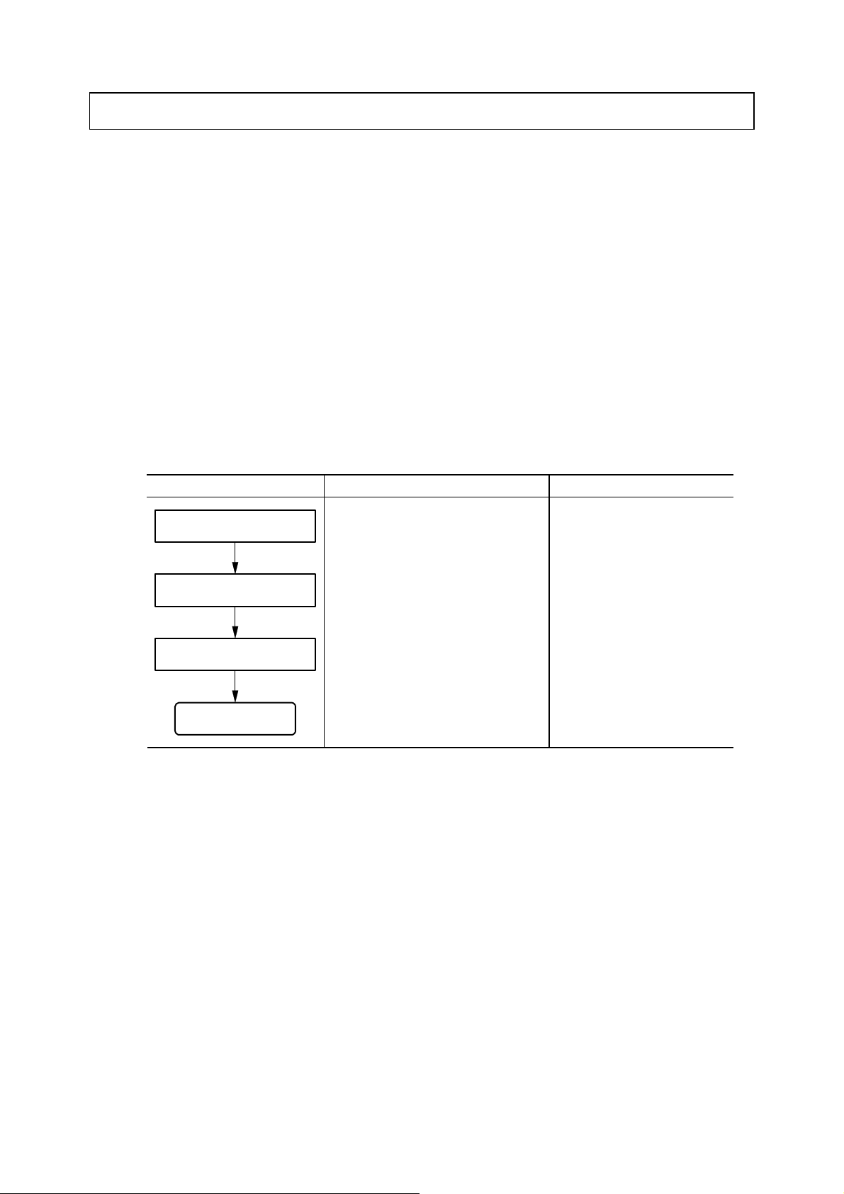
(2) Configuration of the Transmitter for the Measuring System
(a)The reagentless free chlorine analyzer, “Transmitter”, for the measuring system consists of several
elements as described and illustrated in the following table and figure.
(b)The vibrating type residual free chlorine detector, Model: CLV series, is an detector developed for
priority on “easy to handle” and “low cost”. On the other hand, the rotating type residual free
chlorine detector, Model: CLR-21-A, is an detector developed for stable measurement. Therefore,
please specify which detector to be incorporated with the Transmitter when placing order. Note
that the Transmitter needs to be returned to DKK-TOA to change its setting if it is requested to
change the type of the incorporated detector to the other one.
(c)The flow cell, Model: CLZ-4, is made of acrylic and provided with a sampling valve and a flow
regulating valve for laboratory analysis.
Model: CD-36D 1. General
-
7
-
Configuration of the Transmitter for the Measuring System
Item Model Remarks
Reagentless free chlorine analyzer Transmitter CD-36D Transmitter
Vibrating type residual free chlorine detector or
Rotating type residual free chlorine detector CLV series or
CLR-21-A Detector
Flow cell for residual free chlorine detector CLZ-1 Flow cell
[as option]
Column for measurement of pure water CLZ-2 Flow cell
Flow cell for residual free chlorine detector CLZ-4
Pole stand B150
Detector L e a d W i r e s
FlowCell
Model:CLZ-1 Transmitter
Model:CD-36D
Receiver
Columnformeasurement
ofpurewater(option)
Model:CLZ-2
SampleWater
Valve Pressure
Reducer
Notsupplied
Configuration of the Transmitter for the Measuring System
Model: CD-36D 1. General
-
8
-
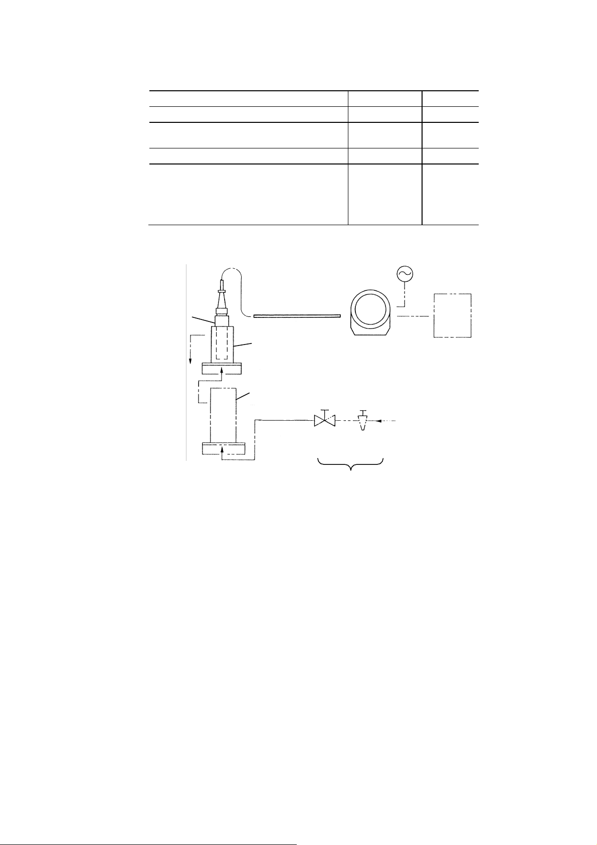
(3) External View
Front Cap
Rear Cap
Fittings for Installation
Casing
Reagentless Free Chlorine Analyzer, “Transmitter” Model: CD-36D
Vibrating Type Residual Free Chlorine Detector
Model: CLV Series Lead
Lead Wires: 1.5m (Standard)
Flow Cell for
Residual Free Chlorine Detector
Model: CLZ-1
Rotating Type Residual Free Chlorine Detector
Model: CLR-21-A
Lead Wires: 1.5m (Standard)
Model: CD-36D 2. Names of Major Parts
-
9
-
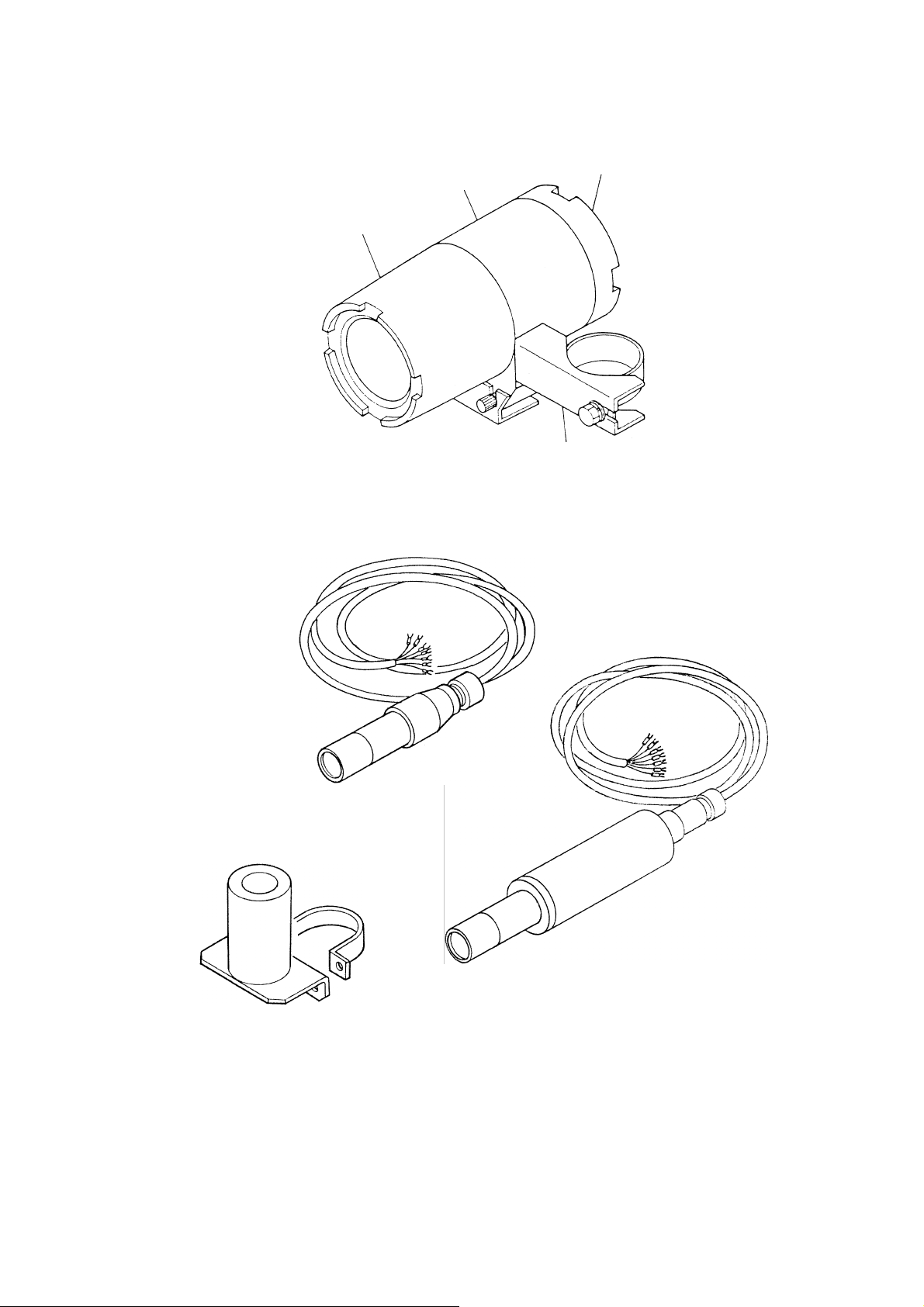
2. Names of Major Parts
Front Cap
Digital Display
Knob Cover:
To prevent knobs
for calibration from
inadvertent touch.
“ZERO Knob:”
For zero adjustment in
calibration
Display of
Measuring
Range
Fixing Screw
for Cover
“SPAN Knob:”
For span adjustment
in calibration
Mode Switch:
To switch the mode to
“MEAS” for “Measurement” mode and
“TEST” for “Maintenance” mode
Cable for
Output Signal Detector
Lead Wires
Cable for
Power supply
Power Switch
(POWER)
Earth Line
Pilot Lamp:
To display the mode presently set,
If “ON” cin “MEAS” mode
If blinking cin “TEST” mode
Transmitter
Connector
Sample Outlet
Lead Wires
Detector
Flow Cell
(Model: CLZ-1)
Sample Inlet
Sample Outlet
Lead Wires
Detector
Flow Cell
(Model: CLZ-1)
Sample Inlet
Connector
Vibration type residual chlorine detector
CLV Series
Rotation type residual chlorine detector
Model CLR-21-A
NOTE Flow cell incorporated with an detector is called “Sensor” in this instruction manual.
Sensor
Model: CD-36D 3.1 Filling of Beads
-
10
-
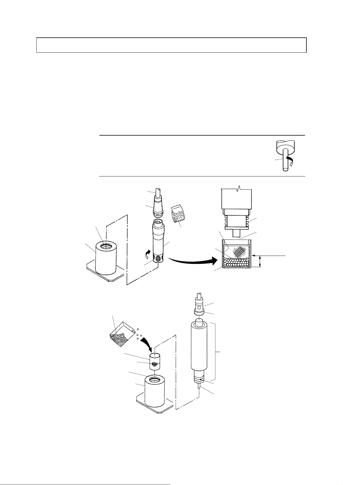
3. Preparation for Operation
3.1 Filling of Beads
①Remove the detector. ⋅⋅⋅⋅⋅⋅ Prepare the beads supplied with the detector, and withdraw the
detector vertically from the flow cell.
②Fill beads. ⋅⋅⋅⋅⋅⋅ Loosen the detector cap and remove it. Then, fill the cap with beads to the level
notch as shown in the following figure.
• For CLV series ⋅⋅⋅⋅⋅⋅ Ceramic or glass beads
•For Model: CLR-21-A ⋅⋅⋅⋅⋅⋅ Ceramic beads
【IMPORTANT】•Turn the sensing electrode clockwise and make sure
the electrode is fixed firmly. Loosening of the
electrode may cause a failure of the product. Sensing
electrode Fix
Beads Wire Mesh.
Ceramic
Beads
Cap
Counter
electrode
Sensing
Electrode
Beads Level
Notch
Beads to
be filled
Lead Wires
Connector
Detector
Rotate to
remove.
Cap
O-ring
Flow Cell
<In case of CLV series>
<In case of Model: CLR-21-A>
Beads
Cap
Level Line
O-ring
Flow Cell
Connector
Closing Ring
Detector
Counter Electrode
Sensing Electrode
Filling of Beads

Model: CD-36D 3.2 Filling of Sodium Chloride Tablets
-
11
-
③Clean the threads of the cap. ⋅⋅⋅⋅⋅⋅ Immerse the cap in water to make beads attached on threads
settle in cap and to clean the threads so that no beads remain on the threads.
④Put the cap back. ⋅⋅⋅⋅⋅⋅ Reinstall the cap on the top of the detector paying attention not to spill
beads from the cap.
⑤Return the detector to the original state. ⋅⋅⋅⋅⋅⋅ Insert the detector slowly and vertically into the
flow cell until it touches the bottom of the flow cell, and connect the connector of the detector lead
wires like before if it was disconnected to remove the detector.
3.2 Filling of Sodium Chloride Tablets
(For specifications with a conductivity modifying column (option))
In order to achieve stable measurement when the conductivity of a sample is in the neighborhood of 3
8 mS/m or less, a conductivity modifying column (Model: CLZ-2) is provided to be combined as
option. In this case, fill sodium chloride tablets as shown below.
Lid
Container
Cell
Filter
Sample Outlet
Sample Inlet
Sodium Chloride Tablets
Code No.: 143A203
(Supplied as option)
Filling of Sodium Chloride Tablets
Model: CD-36D 3.3 Introduction of Sample Water
-
12
-
①Fill the container with sodium chloride tablets. ⋅⋅⋅⋅⋅⋅ Open the lid of the container and fill it with
sodium chloride tablets to its level of ca. 80%.
②Close the lid. ⋅⋅⋅⋅⋅⋅ Close the lid tight.
• The lid must be closed securely when introducing the sample water.
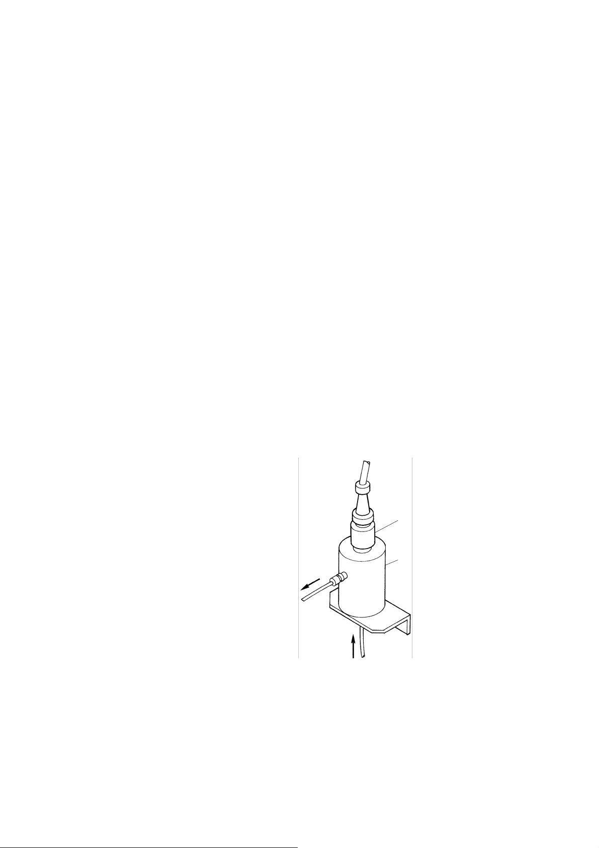
3.3 Introduction of Sample Water
Detector
Flow Cell
Sample Inlet
Sample Outlet
(Flow Rate: ca. 100mL/min)
Introduction of Sample Water to the Sensor
①Confirm that the sensor is ready for introduction of the sample water. ⋅⋅⋅⋅⋅⋅ Confirm that the
sample line is correctly connected the sample inlet and the detector is fixed properly.
②Introduce the sample water. ⋅⋅⋅⋅⋅⋅ Introduce the sample water to the sensor and confirm that the
sample is flowing under the following conditions.

Model: CD-36D 3.3 Introduction of Sample Water
-
13
-
[Conditions of Sample Water]
• pH··································6.5 to 7.5pH
• Electrical conductivity····Equal to or higher than 8 mS/m
• Temperature ···················0 to 40°C (without freezing)
• Pressure ························· 0.01to 0.15MPa
• Consumption··················50 to 200mL/min
• Flow Rate·······················ca. 100mL/min (Roughly speaking, a flow rate of about half of a glass
in a minute)
• Setting Range·················50 to 200mL/min,
If a conductivity modifying column is adopted as option ⋅⋅⋅⋅⋅ 50 to
70mL/min “9. Option”
【IMPORTANT】•Maintain the electrical conductivity of the sample water constant since the
up or down of the electrical conductivity affects the indication.
•Set the flow rate of the sample water to ca. 100mL/min and maintain it
constant since the up or down of the flow rate also affects the indication.
[If a conductivity modifying column is adopted as option]
• If a conductivity modifying column (Model: CLZ-2) is adopted as option, confirm that the lid of
the container of the column is closed tight before starting introduction of the sample water.
Upon introducing the sample water, gradually loosen the lid of the container and the sample level
begins to rise in the container. Then, wait until the sample level in the container reaches ca. 20%
from its bottom.
When the level reaches ca. 20% in the container, close the lid tight.
【IMPORTANT】•If the sample is introduced when the lid is loose, the container will be
completely filled with sample. Make sure to close the lid tight at the
sample level of ca. 20%.
If it is found that the level has risen over ca. 20%, close the sample flow
regulating valve first, and loosen the lid. Then, when the level decreases
to ca. 20%, close the lid tight and open the sample flow regulating valve.
•If the Transmitter is left without sample flow for a long period, the sodium
chloride solution flowing out of the container may be dried up on the
surface of the filter and the filter may be clogged with dried sodium
chloride. Therefore, always keep the sample flowing. When the operation
is to be resumed after a long-term shutdown, start the measurement after
confirming that the crystal of sodium chloride on the filter has completely
been dissolved with the sample water.
③Adjust the flow rate. ⋅⋅⋅⋅⋅⋅ Adjust the sample flow rate with the sample flow regulating valve
provided in the sample line so that a small amount of the sample water overflows in the flow cell.
④Check for any leak. ⋅⋅⋅⋅⋅⋅ Check the entire unit of the sensor to see if there is any leak of the
sample water.
Model: CD-36D 4.1 Start-up Procedure
-
14
-
4. Operation
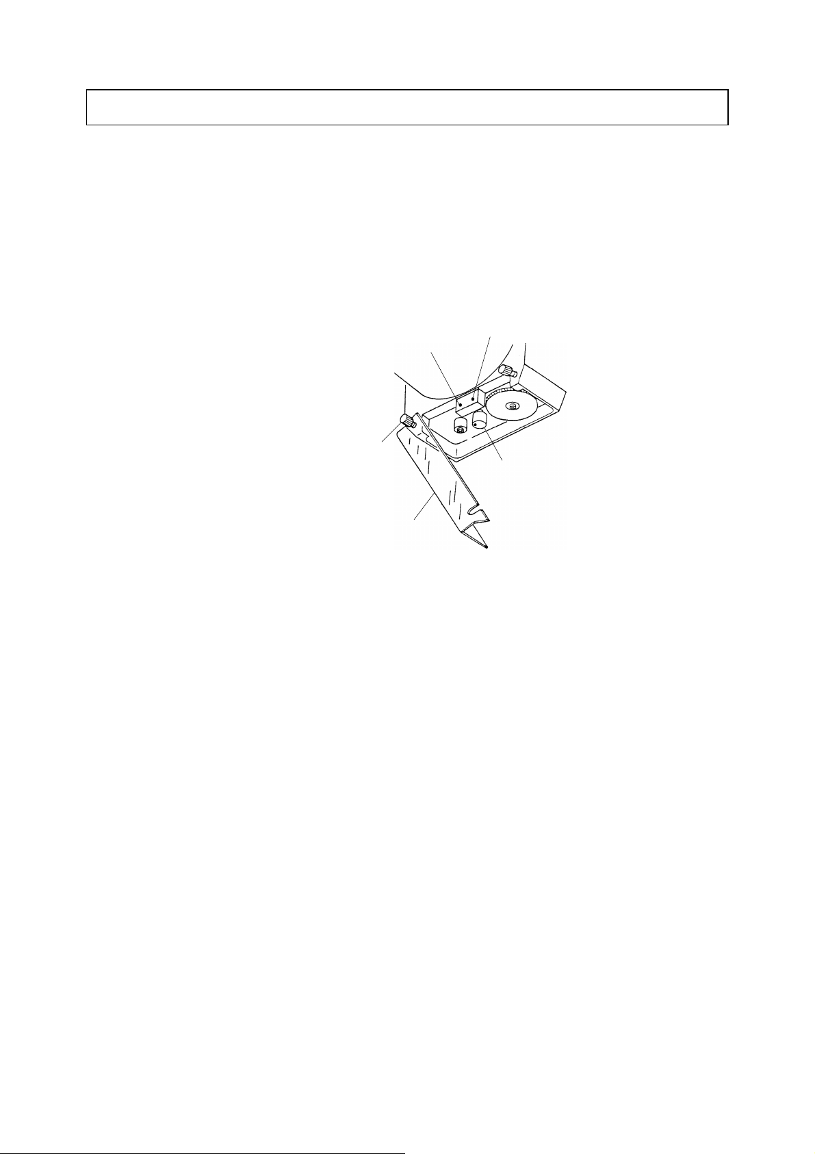
4.1 Start-up Procedure
①Confirm that the installation work and preparation are all finished. ⋅⋅⋅⋅⋅⋅ Confirm that “8.
Installation” (Installation, Piping, Wiring) and “3. Preparation for Operation” (Filling of Beads,
Introduction of Sample Water, etc.) are finished.
②Change to “Maintenance” mode. ⋅⋅⋅⋅⋅⋅ Loosen a little 2 fixing screws for cover and open its right
hand side. Then, turn the mode switch to “Maintenance” (TEST).
“Maintenance mode”
(TEST)
“Measurement mode”
(MEAS)
Mode Switch
Fixing Screw for Cover
Knob Cover
Position of the mode switch
〔NOTE〕•If the mode switch is turned to “Maintenance” mode (TEST), the output signal
automatically changes to a constant value near the median of the measuring range
regardless of the actual indicated value.
•If mode switch is turned to “Measurement” mode(MEAS), output signals for not only the
measured value of the sample water but also other indicated value are delivered giving
influence to the related controlling systems. Therefore, it is advised that the mode should
be set to “Maintenance” mode (TEST) when the measurement is not normal.
③Supply the power. ⋅⋅⋅⋅⋅⋅ Supply the power to the Transmitter.
④Confirm the line voltage. ⋅⋅⋅⋅⋅⋅ Open the rear cap and connect a voltmeter to terminals “90, 91”.
Then, confirm that the line voltage aggress to the one indicated in the name plate attached on the
upper side of the Transmitter.
Model: CD-36D 4.1 Start-up Procedure
-
15
-
Power Switch
(POWER)
Voltmeter
Confirm the line voltage.
Electric Shock
● Since AC power supply is connected to terminals “90, 91”, make sure to turn off the
power supply to the Transmitter on the power supply side in case some work is
needed near the terminal board.
【IMPORTANT】•Do not turn on the power switch when the flow cell is not filled with sample
water since the sensing electrode may be damaged if it is kept vibrating or
rotating in the air for a long period.
⑤Confirm that the pilot lamp is blinking. ⋅⋅⋅⋅⋅⋅ Turn on the power switch located on the upper part
of the terminal board, and confirm that the pilot lamp is blinking, which indicates the present mode
is in “Maintenance” mode.
⑥Change to “Measurement” mode. ⋅⋅⋅⋅⋅⋅ When the indication is stabilized, turn the mode switch to
“Measurement” mode (MEAS), and confirm that the pilot lamp is lit continuously without blinking.
Front Cap
Digital Display
Pilot Lamp:
Display of
Measuring Range
Mode Switch
If continuously lit
If blinking in “Measurement” mode (MEAS)
in “Maintenance” mode (TEST)
Confirm that the pilot lamp is blinking.

Model: CD-36D 4.2 Shutdown of Operation
-
16
-
⑦Confirm the measuring range. ⋅⋅⋅⋅⋅⋅ The measuring range is preset to “0 to 2mg/L” by DKK-TOA
before shipping. If alteration of the measuring range is needed, refer to “6.1 Setting of Measuring
Range”.
⑧Close the rear cap. ⋅⋅⋅⋅⋅⋅ Close the rear cap tight.
⑨Execute calibrations. ⋅⋅⋅⋅⋅⋅ According to “5. Calibration”, execute “Zero” and “Span” calibrations.
⑩Confirmation. ⋅⋅⋅⋅⋅⋅ Confirm the following.
• The mode switch is in the position of “Measurement” (MEAS) and the pilot lamp is continuously
lit.
• Sample water is being fed to the flow cell in accordance with the intended conditions.
• The knob cover and the rear cap are correctly back in the original position.
Now, at this point, the Transmitter is in the normal state for measurement.
4.2 Shutdown of Operation
(a)Take the following steps to stop the operation of the Transmitter.
• Stop the supply of the sample water.
• Turn off the power switch. (Power: OFF)
(b)If the operation is to be resumed after shutdown of the operation, execute the span calibration.

Model: CD-36D 5. Calibration
-
17
-
5. Calibration
(a)When starting the operation of the Transmitter, it is necessary to execute the calibration in order to
adjust the characteristics between the detector and the Transmitter. Additionally, make sure to
execute the calibration on a regular basis during operation in order to maintain accurate
measurement.
(b)If the position of the “ZERO” knob seems to have moved from the original position set at the time
of starting the operation, execute both of the zero and span calibrations. In other cases, only the
span calibration will be sufficient.
(1) Zero Calibration
①Change to “Maintenance” mode. ⋅⋅⋅⋅⋅⋅ Loosen a little 2 fixing screws for cover and open its right
hand side. Then, turn the mode switch to “Maintenance” (TEST).
“Maintenance mode”
(TEST)
“Measurement mode”
(MEAS)
Mode Switch
Fixing Screw for Cover
Knob Cover
“SPAN” Knob
“ZERO” Knob
Position of the mode switch
〔NOTE〕•The calibration can also be executed in “Measurement” mode (MEAS). However, in this
case, the related controlling system will be disturbed since the output signal changes up
and down during the said calibration.
②Disconnect the lead wire “1”. ⋅⋅⋅⋅⋅⋅ Open the rear cap and disconnect the lead wire “1” from its
terminal.
Electric Shock
● Since AC power supply is connected to terminals “90, 91”, make sure to turn off the
power supply to the Transmitter on the power supply side in case some work is
needed near the terminal board.
〔NOTE〕•By disconnecting the lead wire “1” from its terminal, the output signal of the detector to
the Transmitter or the input signal to the Transmitter becomes equal to 0mg/L.

Model: CD-36D 5. Calibration
-
18
-
Disconnect the lead wire
“1” from its terminal.
Disconnect the lead wire “1”.
③Adjust the zero point. ⋅⋅⋅⋅⋅⋅ Wait until the indication stabilizes (for ca. 1 to 2min), and then, adjust
the indication to “0.00”mg/L by turning the “ZERO” knob.
④Connect the lead wire “1”. ⋅⋅⋅⋅⋅⋅ Connect the lead wire “1” back to the terminal “1” like before.
⑤Close the rear cap. ⋅⋅⋅⋅⋅⋅ Close the rear cap tight.
⑥Change to “Measurement” mode. ⋅⋅⋅⋅⋅⋅ Turn the mode switch to “”Measurement mode (MEAS)
and confirm that the pilot lamp is lit continuously.
At this point, the zero calibration is finished. Now, proceed to the span calibration.
(2) Span Calibration
The span calibration is an operation to adjust the indication of the Transmitter to an analyzed value
obtained with “DPD method”, “Amperometric titration method”, etc. for the residual chlorine in the
sample being measured.
①Aging. ⋅⋅⋅⋅⋅⋅ Under the conditions for measurement, let the sample flow through the flow cell for
more than 30 minutes as aging before starting the span calibration.
②Analyze the residual chlorine in the sample with another method. ⋅⋅⋅⋅⋅⋅ Collect a portion of the
sample water out of the flow being supplied to the flow cell when the concentration of the residual
chlorine in it is stable for analysis with “DPD method”, “Amperometric titration method”, etc.
③Adjust the span value. ⋅⋅⋅⋅⋅⋅ By turning the “SPAN” knob, adjust the indication of the Transmitter
to the analyzed value obtained in the previous step ②.

Model: CD-36D 5. Calibration
-
19
-
“Maintenance mode”
(TEST)
“Measurement mode”
(MEAS)
Mode Switch
Fixing Screw for Cover
Knob Cover
“SPAN” Knob
“ZERO” Knob
Position of the “SPAN” Knob
④Fix the knob cover in place. ⋅⋅⋅⋅⋅⋅ Put the knob cover back in place and tighten 2 fixing screws for
the knob cover.
【IMPORTANT】•When the calibration is finished, do not touch the “ZERO” and “SPAN”
knobs. If it seems to have been touched and moved inadvertently, repeat
the calibration from the beginning.
Table of contents
Other TOA-DKK Measuring Instrument manuals


Popular Measuring Instrument manuals by other brands


Vaisala
Vaisala HUMICAP HMP5 quick guide

SIGLENT
SIGLENT SDS2352X-E user manual

PCB Piezotronics
PCB Piezotronics 353B34 Installation and operating manual

CCS
CCS WattNode WNC-3Y-208-MB Installation and operation manual

Würth
Würth MULTI-TESTER PRO II LCD Translation of the original operating instructions

SpiroHome
SpiroHome Lite user manual