TOA 500 SERIES
Installation
Output Connections
CAUTION
Do not remove the cover to prevents an electric shock.
Input Connections
CAUTION
When connecting speakers to any one of the outputs of 4
ohms, 25V or 70V.
Do not block cover ventilation holes.
The amplifier should not be placed in areas;
1) with poor ventilation.
2) exposed to direct sunlight.
3) With high ambient temperature or adjacent to
heat-generating equipment.
4) with high humidity or dust levels.
5) susceptible to vibration.
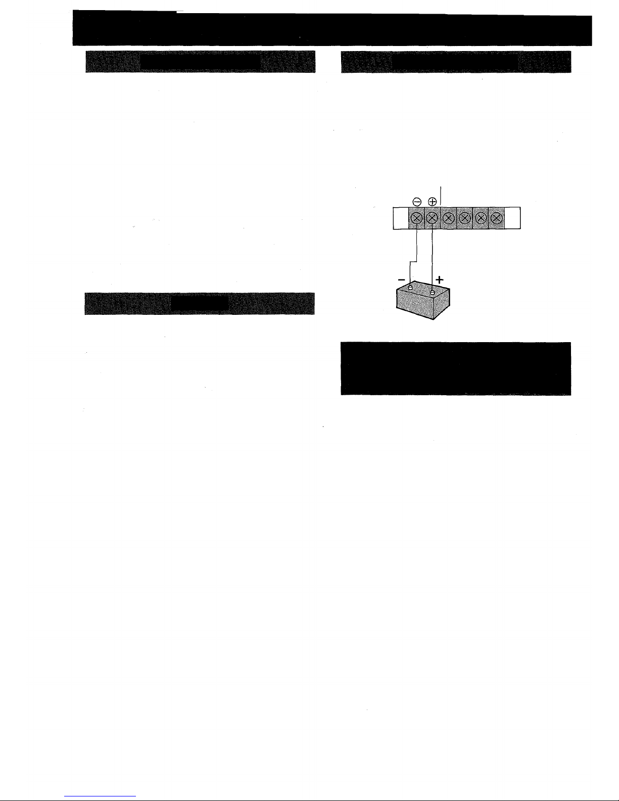
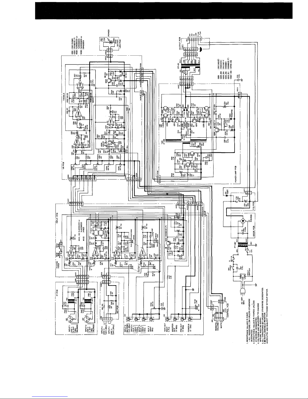
Speaker output
The speaker outputs of the amplifier are 4 ohms, 25V, and 70V.
Connect the speakers cable to one of these outputs, after removing
the screw terminal cover. Put the cover back on when finished the
connection.
Class 2 wiring may be used.
Since these outputs consist of 4 ohms, 25V and 70V via the output
transformer (matching transformer) the connecting method differs in
each case.
See the following diagrams.
Note: Impedances indicated below imply total speaker system
(load) impedances.
<A-503A>
Output Terminal
<A-506A>
Output Terminal
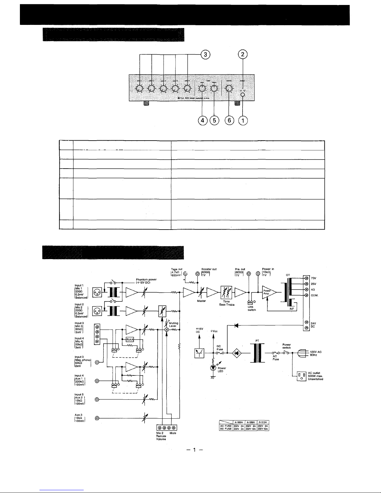
A. Microphone
Four microphone inputs are provided. Two of them may be used with
balanced low impedance (30 - 600 ohms) microphone, or with
condenser microphone. The other may be used with an unbalanced
high impedance (50k ohms) microphone. The microphone with the
unbalanced connection cable of 30 - 70ft or balanced cable 70 - 230ft
may be used depending on the microphone and its characteristic.
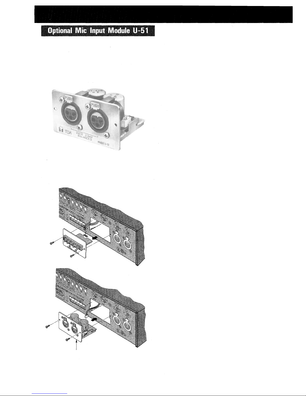
Mic 1 and Mic 2
1) for dynamic microphones — Low impedance (30 - 600 ohms)
balanced microphone inputs are provided with a XLR connector.
2) for condenser microphones - Condenser microphones can be
used with supplying DC 15V phantom power, while turning on the
phantom power switch above the mic input connector.
Mic 3 and Mic 4 — High impedance (50k ohms) unbalanced type
microphone inputs are provided with screw terminals.
Using Mic 3 input, the Input 3 select switch must be turned to Mic 3.
Using Mic 4 input, the Input 4 select switch must be turned to Mic 4.
B. Record player
Record player with MM (moving magnet type) cartridge may be
connected to Mag. Phono input (2mV, 50k ohms).
Use single or double conductor shielded cable with a terminating
RCA pin plug. It is recommended that a separate ground wire be
connected between the record player base and the earth ( )
screw terminal on the rear panel.
C. Radio tuner, cassette tape player and other BGM sources
A radio tuner, tape player, chime, mixer preamplifier, compact disk
player or other high level signal sources may be connected to the
AUX-1, AUX-2 or AUX-3 input.
Use single or double conductor shielded cable with a terminating
RCA pin plug.
<A-512A>
Output Terminal
- 3 -