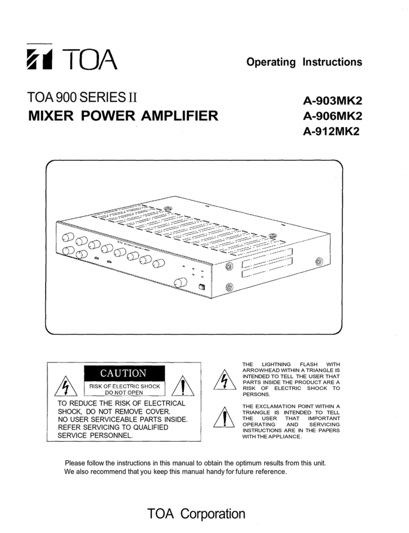
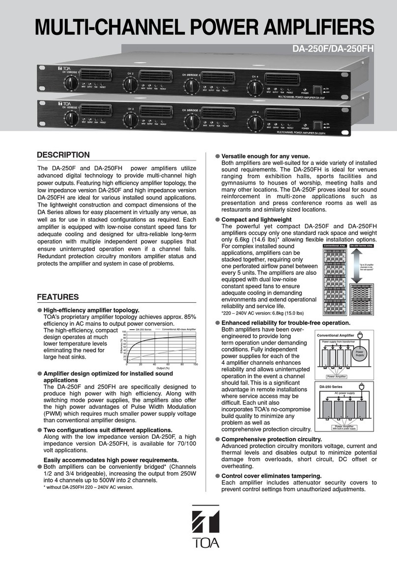
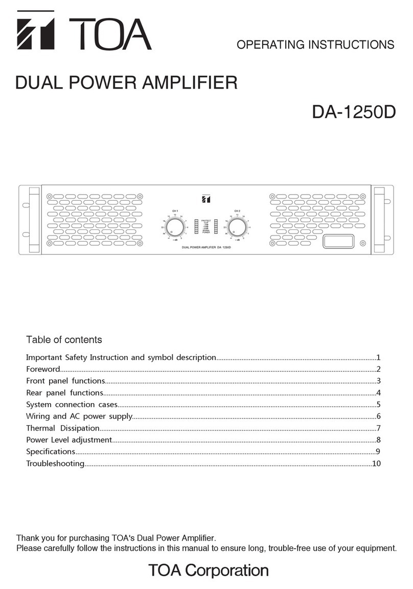
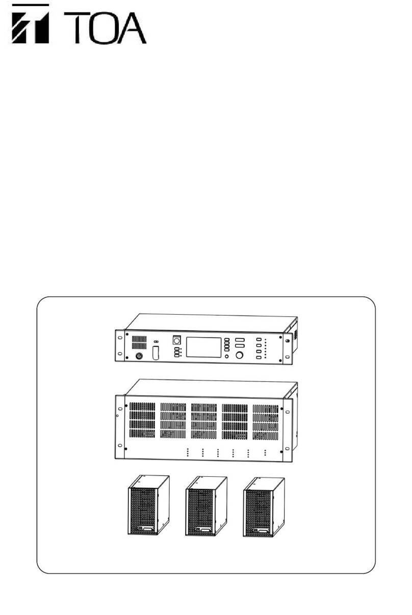
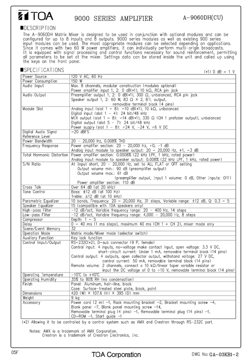
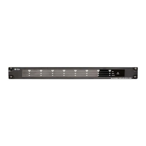
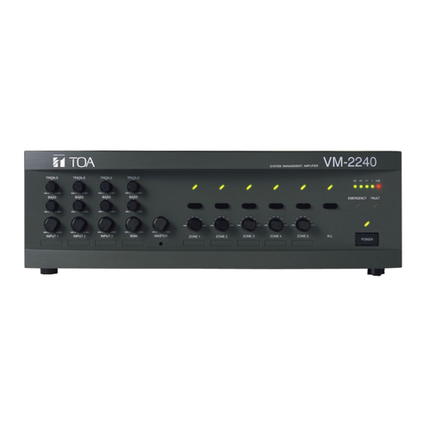
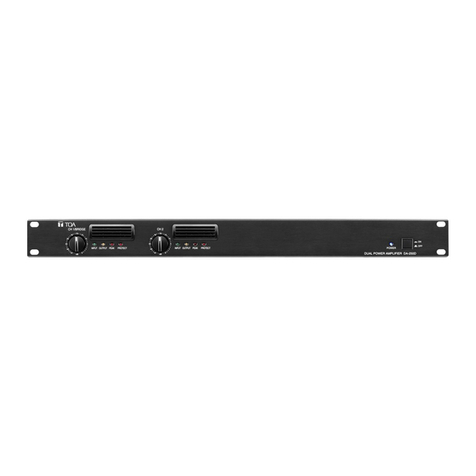
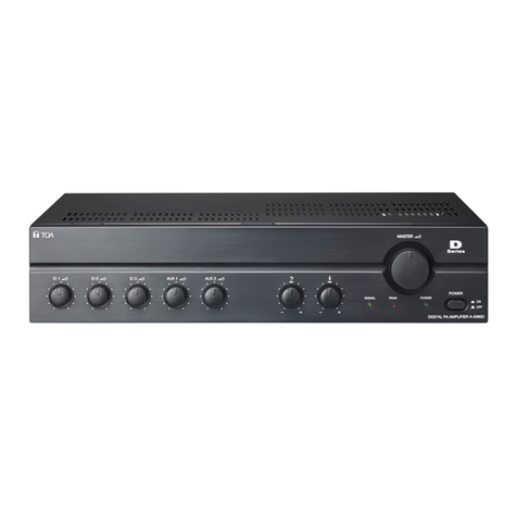
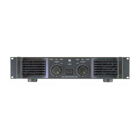
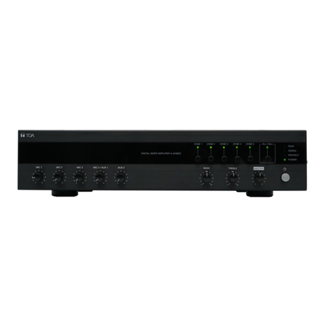
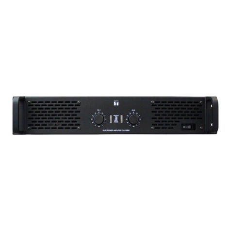
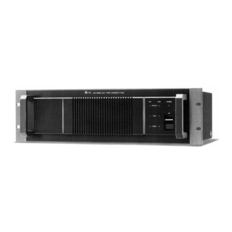
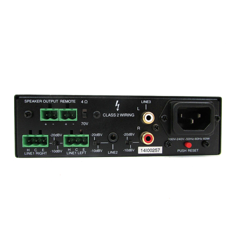
Toa DA-X1000S Assembly instructions

Power Amplifier DA-X1000S
Usermanual
DA-X0130F
DA-X1000S
Power Amplifier DA-X0130F
All electrodes in electrical equipment in the building must have more than 3 mm contact blocking distance.
All-electrode blocking switch and must be installed.
Thank you for purchasing TOA DA-X1000S1&DA-X0130F channel power amplifier.
Before attempting to connect,operate or adjust this Amplifier,please read these instructions completely and
carefully and save this Manual.

5
5
6
7
8
11
12
12
12
13
14
15
15
15
15
16
17
18
Content
1.Safety Instructions 2
2.Summary 4
3.Features 4
4.Use Notes
5.Installation Notes
6.Name and function of each part
6.1 Front panel
6.2 Rear panel
9
7.Setting and connection Method
7.1 Switch setting and speaker connection
7.1.1 DA-X1000S connection
7.1.2 DA-X0130F connection 9
8.Connecting method of the detachable wiring plug 10
9.List of Protection Operations
10.Installation of filter support and filter
11.Cleaning of filters
12.Dimensional drawing
13.Integrated circuit diagram
13.1 DA-X1000S
14.Description of wiring connection
14.1 PA LINK
14.2 Pin hole number and line color from Network crystal head
14.3 AUX INPUT
15.Specification
15.1 DA-X1000S
15.2 DA-X0130F
16.Fuse replacement method
1
14.4 OUTPUT
13.2 DA-X0130F

1. Safety Instructions
• Read all instructions-All the safety and operating instructions should be read before operating this apparatus.
• Follow all instructions- All following notes and important security-related issues should be followed.
• Keep the instructions-The safety and operating instructions should be retained for future reference.
• Avoiding being wet within water.
Avoiding letting water into the host or getting wet within water.To reduce the risk of fire , items such as vases
filled with liquid should not be placed on the apparatus.
Do not use beyond the marked power supply voltage.
Otherwise, it will causes fire and electric shock.
• Do not damage the power cable.
Do not damage the power cable, or process it, or close to the burning appliance.
In addition, do not place heavy objects on the cable.
Otherwise it will causes a fire.
• Protective earthing of the power instalation.
The apparatus should be connected to a mains socket outlet with a protective earthing connection.
• Abnormal conditions.
When the following occurs,please cut off the power plug, unplug the apparatus and contact the dealer.
• When there is smoke or smell.
• When water or foreign matter intrudes inside the apparatus.
• When the apparatus falls or the shell is damaged.
• When the power cable is damaged (Wire core exposed , broken, etc).
• When the apparatus has no sound.
• Do not open or modify the apparatus.
Some of the internal voltage is high, if the shell is opened or modified, it will causes fire, electric shock.
Please entrust dealer for internal inspection, adjustment, repair.
• Do not place liquid containers or small metal over the apparatus.
If the liquid enters the apparatus, it will causes fire, electric shock.Items such as vases filled with liquid
should not be placed on the apparatus.
About Marking
During the use:
Warning:
2
The safety markings used in this manual are used to prevent human injury and property damage due to
misoperation.
To prevent potential safety hazards, please read this manual carefully and fully understand these safety
symbols before operating this apparatus.
The marking is intened to alert that user to the potential safety risks
that could lead to death or serious injury in the event of misoperation.
• This apparatus should be operated only from the type of power supply indicated on the rating
label.
• Identified terminal external connection should be operated by professionals .
Setting • intallation
It will causes fire and electric shock, if continuous use under abnormal conditions.

•Don't touch the apparatus when thunder strikes.
Do not touch the socket when thunder strikes.
Otherwise, it may causes electric shock.
• Please do not touch the power plug with wet fingers.
Please do not touch the power plug with wet fingers, otherwise it will causes electric shock.
• Please do not pull the power plug direclty.
When unplug the apparatus, please do not pull the power plug directly.
Otherwise it will causes power cable damage , fire , electric shock.
Please unplug the power cable , and remove it.
• Unplug the power cable when removing the apparatus
If the power cable is not unplug when removing the apparatus , it will causes power cable damage , fire ,
electric shock.
• Please keep the apparatus away from wet and dusty environment.
Do not place in wet, dusty, direct sunlight, burning appliances around, oil fumes and water vapor pollution sites.
Otherwise it will causes fire, electric shock.
•Turn off the power swtich before connection.
It will causes electric shock , if you connect this apparatus without cutting the power supply.
•Attetions to the installation
Please follow the below issues,otherwises it will causes fire , electric shock.
•Install in a stable place and screw it. Prevent shelf dumping and movement.
•When this apparatus is installed in other cabinet except our special cabinet, please use screws with diameter
of 5 mm, and length of 12 mm or more.
•When connecting the power supply to the socket, it shall not exceed the rated current of the socket.
•Before turning on the power, the INPUT VOL adjustment button should be turned to the
position of - ∞ .
•Do not use it for a long time when the sound quality is abnormal.
It may causes speaker overheating and causing a fire.
•Please do not put foreign bodies inside the apparatus.
Please do not insert or drop the metal or flammable material from the vent of the apparatus.
Warning:
The marking is intened to alert that user to the potential safety risks that
could lead to death or serious injury in the event of misoperation.
Otherwise it may causes fire, electric shock and so on.
Attention:
The marking is intened to alert that misoperation can cause moderate or
minor personal injury or property damage.
3
If the INPUT VOL adjustment button is not turned to - ∞ , it may causes a sudden change,which will
lead to hearing impairment.
During the use:
Setting • intallation
During the use:

2. Summary
DA-X1000S is 1 channel *1000 W,Class D power amplifier with high output durable of constant voltage.
DA-X0130F is 4 channels *130 W,Class D power amplifier with high output durable of constant voltage.
Can be used as a residential area, schools, squares, high-speed rail and other professional broadcast system
after the sound drive amplification, using efficient switching power, strong output power.
3. Features
•Can be installed in 2 U size space cabinet.
•Low power consumption, light weight.
•DA-X1000S transfers the INPUT signal from the rear panel to OUTPUT channel.The volume of the output
signal can be adjusted by the input volume potentiometer.(DA-X0130F can use 4 channels,INPUT CH1/2/3/4
refers to OUTPUT1/2/3/4)
•Electronic balanced input.
•Input terminals use detachable wiring plug and RJ45 connector that can be easily connected to VX-1000S system.
•Each channel is provided with a LED indicator showing the status of input and output, protection.
•Short circuit, overload and abnormal temperature rise, the output and load can be cut off by the built-in protection
circuit.
•Internal information (power ON/OFF status, protection status, mode switching) is available.
*1 U =44.5 mm( standard size)
• Precautions for a long absence and during the maintenance.
Unplug the apparatus during the maintainance or when unused for long periods of time.
Otherwises it will causes a fire,electric shock.
• Regular internal clearance.
Please consult the dealer about the internal cleaning.
Accumulation of dust inside and prolonged non-cleaning may lead to fire.
• Clean the plug socket.
Ash in the socket may cause a fire. So please clean the socket regularly.
4
Attention:
The marking is intened to alert that misoperation can cause moderate or
minor personal injury or property damage.
During the use:
In addition, please plug the plug to the bottom of the socket.
4. Use Notes
•Please place the input cable separately from the output cable, otherwise it may causes resonance.
•Please use the specified constant voltage loudspeaker. It may lead to the output power failure when
connecting the loudspeaker beyond the specified voltage.
•There is a filter in front of the apparatus, please clean the filter regularly, if the filter is blocked, it may lead to
abnormal heat dissipation.
•Please use in places where temperature-10~40℃ humidity below 90% RH (no condensation) is present.
•When cleaning the equipment, be sure to break the power switch of the equipment first,then wipe it
with a dry towel, and if you encounter more difficult stains, you can do so in theuse appropriate amount
of neutral cleaning agent to clean the towel. Do not use gasoline,diluent,alcohol and other chemicals,
otherwise it may causesdeformation, discoloration and other conditions.
•This apparatus is using the power plug and appliance coupler to cut off the main power supply.Place the
power plug or the appliance coupler in the most convenient position during the use.In order to facilitate the
occurrence of danger, the power supply can be disconnected timely and accurately.
6. Name and function of each part
DA-X1000S
DA-X0130F
1. Output indicators (SIGNAL)
These indicators show current signal output level.
2. Clip indicators (PEAK)
These indicators warn against overload shortly on the each output channels. We would like to recommend for
users to adjust VOLUME control when CLIP indicators are flickering to make best performance.
3. Proctect indicators (FAULT)
The red light flashes when the apparatus has short circuit, the orange light flashes when the apparatus has
other faults.
4. The AUX auxiliary signal input indication (AUX ACTIVE)
The orange light flashes when the ACTIVE is short connected, and when the AUX auxiliary signal is inputted.
5. Power indicators (POWER)
The green light flashes when the computer is on.
6. Power switch (ON/OFF)
Power switch button,press up for ON and press down for OFF.
16
16
6.1 Front panel
6

MODEL (型号): DA -X 01 30 F- AS M OD EL (型号):DA-X1000S-AS
MODEL (型号): DA -X 01 30 F- AS
MODEL (型号): DA -X 10 00 S- AS
DA-X1000S
DA-X0130F
1
1
1. AC power input connection (AC INPUT)
2. Amplifier outputs (100V OUTPUT)
A correct capacity of fuse and power cable should be applied. Please make sure the value of fuse before
replacing.
These amplifier output blocks provide 100V constant voltage output for commercial and industrial use.
3. Volume controls (INPUT VOL)
The volume potentiometer adjusts the output level.
4. Signal input and signal swtich controls (AUX INPUT)
The AUX auxiliary signal is outputted when the ACTIVE is short connected. When the ACTIVE is disconnected,
the PA LINK signal is outputted.
5. RJ45 Network connector (PA LINK)
Start "PA LINK", DA-X AMP conectes to VX-1000MC for use.
6.2 Rear panel
7
OUTPUT (输):1000W
(AC输)
(AC输)

7. Setting and connection method
AC power input speaker output terminal
signal input terminal
volume output
RJ45 Network
connector
Step 1. turn off the power supply.
Step 2. When the network port emergency signal switches to the AUX regular broadcast signal, the connector
ACTIVE-A is short to the ACTIVE-B.
Step 3. Connect the speaker cable to the power amplifier output terminal via the detachable wiring plug.
Step 4. turn off the power supply.
4-1. Peel the speaker wire cover (as attached image) about 7 MM. (Reference P10)
4-2. Connect the speaker cable to the attachment detachable wiring plug. (Reference P15)
4-3. Connect the detachable wiring plug to the power amplifier output terminal.
The metal part of the power amplifier output terminal has high voltage power.
Please do not touch it directly by hand, otherwise it will causes electric shock and
causes personal injury.
Figure is from DA-X0130F.
Warning:
8
(AC输)
7
MODEL (型号): DA -X 01 30 F- AS
MODEL (型号): DA -X 10 00 S- AS

7.1 Switch setting and speaker connection
7.1.1 During the use of DA-X1000S
[1 input 1 output ]
7.1.2 DA-X0130FDuring the use of
67Ω
67Ω
67Ω
67Ω
10Ω
ACTIVE connector disconnected
The volume
potentiometer
The volume potentiometer
adjusts the lowest level.
Power switch OFF
9
(Factory Setting)
[4 input 4 output ] (Factory Setting)
ACTIVE connector disconnected
The volume
potentiometer
The volume potentiometer
adjusts the lowest level.
Power switch OFF

8. Connection of detachable wiring plug
Attentions
• Be sure to use the shield wire.
• Please pay attention to the exposed part of the wire. Please avoid tin plating.
When tying the wire, if the solder is damaged, it may increase the contact resistance, resulting in an abnormally
increased temperature at the contact site.
Use the AWG 16-28 type for the wire type.
• Exposed part of the wire
• Connection steps for the connector.
Step 1. Unscrew the screw in the terminal and insert
the cable.
Step 2. Tighten the screw in the terminal.
Make sure the wire is not extended
and elongated.
Remark
Recommended one-shaped screwdriver: the width of the blade mouth is about 3 MM.
Shape of the screwdriver knife port
10
one-shaped screwdriver
tighten unscrew
detachable wiring plug
terminal screw
1
5
ACTIVE-B
ACTIVE-A
E (GND)
C (-)
H (+)

9. List of Protection Operations
Abnormal Condition Protection The operation display Solution Reset
Overload current
The current limiter
starts in operation
when the specified
impedance is
insufficient.
The peak or protection
indicator is on. Remove overload Automatic reset after
connecting the normal
load.
Short circuit The current limiter
starts to run.
The operating indicator
of the protection circuit
is on.
Check the speakers,
lines, etc. for a short
circuit.
Cut off the power switch
of this equipment.After
normal load, power on.
Over-voltage,
Under-voltage
The power amplifier
protection circuit starts
to run.
The protection indicator
light is on.
Heat-sink temperature
of power amplifier
(above 160 ° C)
Power board power-off
protection.
Check the ventilation
condition and check if
fan is overloaded.
After the temperature
drops, it will be
automatically reset.
Temperature rise of
cooling board in power
supply site
(above 85 ° C)
The built-in power
board unit that causes
the temperature to rise
stops working.
11
The indicator of the
corresponding
channel will go off.
Check the power
board or amplifier
board for damage ,
repair bad board.

10. Installation of filter support and filter
Install the filter first , and then lock the filter support. Please check the below image.
11. Cleaning of filters
Step 1 turn off the power supply.
Step 2 remove the ventilation panel.
Step 3 unscrew the screw, remove the bracket.
Step 4 remove the filter inside the panel.
Step 5 remove the dust inside the filter.
12. Dimensional drawing
12
432.2
426.5
392.3
88
483
screw
filter support filter
Step 6 lock the filter with the filter support.
Size unit:mm
screw filter support
filter

13.Integratedcircuitdiagram
13.1DA-X1000S
13

14
13.2DA-X0130F

14. Description of wiring connection
14.1 PA LINK
14.1.1 RJ45 network input
1. H (+)
2. C (-)
3. LINK-PA
4. G (GND)
5. NC
6. DET (Protection port output control,HI-LEVEL for output protection, Lo-LEVEL for normal operation)
7. GND
8. GND
14.3 AUX INPUT
1. Signal switching terminal ACTIVE-B (When ACTIVE-A and B are short conencted,switch to euro
block signal. when ACTIVE-A and B connection is cut , swtich
to RJ45 input signal.)
2. Signal switching terminal ACTIVE-A
3. G (GND)
4. C (-)
5. H (+)
14.4 OUTPUT
1. - (100V Output)
2. + (100V Output)
14.2 Pin hole number and line color from network crystal head
15
1
5
8 7 6 5 4 3 2 1
8
7
6
5
4
3
2
1
Five class of air cables for
LAN connection (CAT5-UTP)
Connect to the control/monitor terminal
RJ45 pin code
line color
(T568B)
line color
(T568A)
pin code
orange/white
orange/white
orange
orange
green/white
green/white
green
green
blue/white blue/white
blue blue
dark brown/ white dark brown/ white
dark brown dark brown

15. Specifications
15.1 DA-X1000S
Model Name
Power Supply
Amplifier
Power consumption
Input
Rated Output
Frequency Response
T.H.D
Protections
S/N Ratio
ACTIVE control input
LED Indicator
Cooling
Operating temperature
Operating humidity
Material
Control
Dimensions
Weight
Accessary
220V-240V〜50/60Hz T6.3AL
Class-D Amplifier
30W(Standby mode), 1200W (rated output of 100V)
1 Channel: PA LINK (dedicated configuration VX-1000MC use)
1 Channel: AUX INPUT (PIN 1,2,3) balanced input, (0dB (1V): input level adjusted to
maximum, input impedance of 20kΩ
1 Channel (2pin):1000W(100V,loading 10Ω)
110〜16,000Hz ±3dB
0.4% (1W),1%( rated output)
Overcurrent protection, under-voltage protection, over-voltage protection, overheat
protection, short-circuit protection
90dB (A-weighted)
The AUX auxiliary signal is outputted when the ACTIVE INPUT(pin4,5) is short connected.
When the ACTIVE INPUT(pin4,5) is disconnected,the PA LINK signal is outputted.
POWER: power supply (green) X1 SIGNAL: signal (green) X1 PEAK: peak (red) X1
AUX ACTIVE: auxiliary input (orange) X1 FAULT: fault (red or orange) X1
The system controls the fan for heat dissipation.
0℃~+40℃
≤90%, which is not condensed
Black aluminum panel, electrolytic plate is sprayed black.
Panel: The power switch
6.16KG (Net weight) 8.14KG (Gross weight)
CCC power cord X1(DA-1000S only) CE power cord X1 UK power cord X1 fuse
T6.3AL X1(built-in) footpad X4 detachable terminal 2P X1 detachable terminal 5P X1
16
Rear panel: 1 Channel input volume adjustment knob
483 (L) X88 (H) X392 (W)
DA-X1000S

15.2 DA-X0130F
17
Model Name
Power Supply
Amplifier
Power consumption
Input
Rated Output
Frequency Response
T.H.D
Protections
S/N Ratio
ACTIVE control input
LED Indicator
Cooling
Operating temperature
Operating humidity
Material
Control
Dimensions
Weight
Accessary
DA-X0130F
220V-240V〜50/60Hz T4AL
Class-D Amplifier
85W(Standby mode), 740W (rated output of 100V)
4 Channel: PA LINK (dedicated configuration VX-1000MC use)
4 Channel: AUX INPUT (PIN 1,2,3) balanced input, (0dB (1V): input level adjusted to
maximum, input impedance of 20kΩ
4 Channel (2pin):130W (100V,loading 67Ω)
0.4%(1W),1%( rated output)
Overcurrent protection, under-voltage protection, over-voltage protection, overheat
protection, short-circuit protection
>83dB (A-weighted)
The AUX auxiliary signal is outputted when the ACTIVE INPUT(pin4,5) is short connected.
When the ACTIVE INPUT(pin4,5) is disconnected,the PA LINK signal is outputted.
POWER: power supply (green) X1 SIGNAL: signal (green) X4 PEAK: peak (red) X4
AUX ACTIVE: auxiliary input (orange) X4 FAULT: fault (red or orange) X4
The system controls the fan for heat dissipation.
0℃~+40℃
≤90%, which is not condensed
Black aluminum panel, electrolytic plate is sprayed black.
Panel: The power switch
Rear panel: 4 Channel input volume adjustment knob
483 (L) X88 (H) X392 (W)
6.96KG (Net weight) 8.94KG (Gross weight)
CCC power cord X1(DA-X0130F only) CE power cord X1 UK power cord X1 fuse
T6.3AL X1(built-in) footpad X4 detachable terminal 2P X1 detachable terminal 5P X1
Crosstalk >70dB (A-weighted)
Necessary modifcations are carried out without notice.
110〜20,000Hz ±3dB

16.Fuse replacement method
Step 1. Turn offthe power supply , unplug the power cable.
Step 2. Remove the power seat safe with a one-shaped screwdriver.
Step 3. Remove the spare fuse from the power socket safety box, replace the previously used fuse, and
install it in the center.
Step 4. Reinstall the socket safety box, to install in place.
18
-
100V OUTPUT 2
+
100V OUTPUT 1
-
+
-
100V OUTPUT 4
+
100V OUTPUT 3
-
+
220V-240V 50/60Hz 740W
FUSE T4.0AL / 250V
PA LINK
H
ACTIVE
AUX INPUT
C
E
VOL
-∞dB 0dB
CH1 INPUT
PA LINK
H
ACTIVE
AUX INPUT
C
E
VOL
-∞dB 0dB
CH2 INPUT
PA LINK
H
ACTIVE
AUX INPUT
C
E
VOL
-∞dB 0dB
CH3 INPUT
PA LINK
H
ACTIVE
AUX INPUT
C
E
VOL
-∞dB 0dB
CH4 INPUT
POWER AMPLIFIER
RATED OUTPUT
(
额输
)
:4x130W
MADE IN CHINA
(
中国制
)
(功⼤)
( )
SIGNAL GND
Power outlet
Remove the power seat safe with a one-shaped
screwdriver
Power socket safety box
Install it in the center
The spare fuse The previously used fuse
MODEL (型号): DA -X 10 00 S- AS

570.100001-TO
Other manuals for DA-X1000S
1
This manual suits for next models
1
Table of contents
Other Toa Amplifier manuals

Toa
Toa KD-1 Instruction Manual

Toa
Toa BG-2060 User manual

Toa
Toa P-75D User guide

Toa
Toa PA-1230B User manual

Toa
Toa 900 II Series User manual

Toa
Toa CA-200 User manual

Toa
Toa A-2060D SERIES User manual

Toa
Toa SA-112 CE User manual

Toa
Toa AV-20D User manual

Toa
Toa BG-2035 Operating and installation instructions