Toa A-9060DH User manual

Everything You
(Really) Wanted to Know
About the 9000 Series
A User’s Guide
Rev 1.1
February, 2008

2
How To Use This Guide
First, congratulations on your choice of the TOA 9000 Series of Modular Mixer /
Amplifiers. The 9000 Series is one of the most versatile and cost-effective audio products
available, designed to function in a myriad of mixing, paging and room-combining
applications. However, as with many DSP-based products on the market today, the 9000
Series does have a reasonable learning curve. This guide is not a substitute for operations
manuals, but should be used in conjunction with them. It is being presented as a means of
illuminating systems designers and installers, as well as end-users with a better
understanding of how to make the most of the 9000 Series’ potential. In short, it is designed
to be your 9000 Series “survival kit”. This will be a simple, concise guide on to how to
configure, program and operate your 9000 Series unit. If you’re reading this, perhaps it
means you’ve tried sifting through chapters in the manual, spent countless hours staring at
the front panel (or GUI) display and now you’re engaged in pulling out hair follicles. You’re
probably just looking for some real-world answers to your questions. In this guide we will
explore (and answer) those questions together.
The Table of Contents is set up to easily find information about the 9000 by topic and by
related questions.
Occasionally, there will be footnotes or vital information denoted by:
*
or by
L
Please pay special attention to these, as they are meant to save you from confusion and
unnecessary aggravation.
This guide is also intended to be a “living” document. As questions and challenges arise from
installers and users alike, we will amend this guide to reflect them.
Lastly, there are links to various other resources at the end, which if used in conjunction with
this guide, should make working with 9000 Series more productive.
Well, let’s go to it!

3
(Page intentionally left blank)

Table of Contents
4
1.
Hardware Configuration (modules, accessories and more ...)
a.
What comes supplied with my 9000 Series unit?……………………............
6
b.
What state is the 9000 when first powered on?………………….…………..
.
6
c.
What function does each module perform?.................................................
.
7
d.
What modules go where?............................................................................
9
e.
What DSP functions are available in each module?....................................
11
f.
When do I use this module?........................................................................
.
12
g.
What if I need more inputs or outputs?........................................................
.
12
12
2.
Gettin
g
Around the Front Panel Controls
a.
What do these buttons do?…………………………………………………..…
.
12
b.
What do these indications on the display mean?........................................
13
c.
How do I edit from the front panel?
i.
In Mixer mode?............................................................................
14
ii.
In Matrix Mode?...........................................................................
.
15
d.
How do I program Events from the front panel………………………………
…
16
3.
Operation Modes (Read This - Really!)
a.
What are the two different modes best used for?........................................
17
b.
How does operation of these two modes differ?..........................................
17
c.
How do I change the operating modes………………………………………
…
19
d.
How do I save a Configuration to my PC?...................................................
20
4.
Programming From the GUI
a.
Mainframe Configuration Settings Page………………………………………
…
21
b.
I/O Module Settings Page (MIXER Mode)………………………………..…
…
23
c.
Scene Settings Page (MIXER Mode)…………………………………..………
25
d.
Paging Settings (MIXER Mode)………………………………………....……
…
26
e.
Output Assignment Settings (MIXER Mode)……………………………..…
…
27
f.
I/O Module Settings Page (MATRIX Mode)…………………………...………
28
g.
Event Settings Page (MATRIX Mode).........................................................
.
29
h.
Volume Settings Page.................................................................................
.
30
i.
EQ Settings Page……………………………………….…………………….….
31
j
.
Compressor Settings Page..........................................................................
32
k.
Remote Settings Page……………………………………………..………….…
33
l.
Control In Settings Page ……………………………………...………………
…
34
m.
Control Out Settings Page…………………………………….…………….…
…
35
5.
Programming In Excel
……………………………………………................
…
35
6.
Communicatin
g
With Your PC
a.
How do I connect a 9000 Series unit to a PC?............................................
37
b.
How do I Upload/Download Configuration presets?....................................
37
c.
What to do if I’ve forgotten my security password?.....................................
.
38
d.
How do I update the firmware on the 9000 unit?.........................................
.
39
Subject Page
h. What are the PRE OUT & AMP IN connections used for?...........................

7. Controllin
g
the 9000 Series
a.
How do I control the 9000 Series from the front panel?..............................
.
40
b.
How do I control the 9000 Series using Remote Control inputs?................
.
40
c.
How do I control the 9000 Series using Serial Control?..............................
.
40
d.
How do I control the 9000 Series using Contact Closures?........................
.
41
e.
Can I emulate contact closures using a PC?............................................... 41
f.
How do I set up a ZM control to be used as a BGM Source selector?
(MATRIX Mode)……………………………………………………………………..……
…
42
8. Paging with the ZP-001T
a.
How do I perform paging using the ZP-001T in Matrix (Normal) Mode?.....
.
43
b.
How do I perform paging using the ZP-001T in Mixer Mode?.....................
.
44
9. Ambient Noise Control with the AN-001T
a.
How does the AN-001T work to compensate for ambient noise?................
4
45
b.
What settings should I use for the AN-001T?..............................................46
10. NOM function (Mixer Mode)
a.
How do I program the 9000 for Auto-Mixing?..............................................
.
47
11. Matrix Sub-Modes
a.
What are the Matrix Sub-Modes used for?.................................................. 48
12. Miscellaneous Stuff
a.
How do I trouble shoot the 9000 Series?.....................................................51
b.
What Happens If I unplug the power cord or power is lost?........................ 51
c.
What do the error messages mean?............................................................52
d.
Where can I find additional 9000 support resources?................................. 53
13. Glossar
y
of Terms
…………………………………………………..……...… 54
55
Subject Page
NOM Table
………………………………………………………...……………
…
5

1. Hardware Configuration
Out of the Box:
a. What Comes Supplied With My 9000 Series Unit?
Generally, ALL 9000 Series mixers are packaged with the following accessories:
6
•IEC Power cord
•Removable control block connector (for Volume 1-2 & control In/Out 1-4)…
•Rack-mount ears (Yey!)
•Blank panels for all module slots except for module slot #1.
•Quick Start Guide for MIXER & MATRIX modes
•CD-ROM containing operations manuals (pdf) for Mixer & Matrix modes, plus
GUI & Excel programming software and Maintenance PC application.
•5 Year Warranty
•There are additional phoenix connectors provided as well. However, these may
vary slightly by model:
oM9000: (2) 3-conductor Phoenix connectors (for
Channels 1 & 2 balanced line
outputs)………………………………………....................
oA-9060DH, 9120DH & 9120DL: (1) four-conductor
phoenix connector (for Channels 1 & 2 speaker
outputs)……………………………………………………..
oA-9060S, 9120S & 9240S:
(1) Balanced Phoenix connector (Channel 2 line
output)………………………………………………………
(1) Two-wire phoenix connector (Channel 1 Speaker
output)……………………………………………………………..
b. What State is the 9000 Series in when it is first Powered On?
•Currently, the 9000 Series in all its forms comes out of the box set to MIXER
Mode. However, when first powered on, all inputs feed all outputs (how many
depending on which modules are installed). This enables you to test the audio
through-put (all sources and all zones) without the need for programming. Once
audio has been verified, you can proceed to program the unit for your particular
needs. Note: When starting the unit in MATRIX mode, this also occurs,
BUT-be aware-this is a one time only offer-ONCE YOU’VE ENTERED THE
MENU OR BEGIN TO CHANGE ANY PARAMETER, THE UNIT GOES TO
MATRIX MODE AND AUDIO ROUTING DISENGAGES (until you program the
signal routing events into it).

c. What function does each module perform?
7
D-001T Dual Mic/Line Input Module with DSP
•Two Balanced Mic / Line Inputs
•Digital Signal Processing:10-Band Parametric EQ , Bass / Treble,
Loudness, High and Low Pass Filters, Compressor, Adjustable
Sensitivity (mic/line) Phantom Power (24 VDC)
•Removable Terminal Block
•Required for VOX (Voice-Operated Switch) function and input
signal level metering
D-001R Dual Line Input Module with DSP
•Two Unbalanced Line Inputs
•Digital Signal Processing:10-Band Parametric EQ , Bass / Treble,
Loudness, High and Low Pass Filters, Compressor, Adjustable
Sensitivity
•Dual summing RCA connectors
•Required for VOX (Voice-Operated Switch) function and input
signal level metering
AN-001T Ambient Noise Control Module
•Automatically adjusts output gain to compensate for changes in
ambient noise level
•Each input can be assigned to control a specific output
•Two inputs with +24VDC phantom power for condenser mics
•14 preset gain ratios
•Accessory sensing microphone available, model AN-9001
ZP-001T Telephone Paging Module
•Telephone Access Paging to up to eight zones
•Uses DTMF dialing to access amplifier and/or line outputs
•Dial up to eight output zones in one operation
•Analog extension or page port compatible
•Page port operation requires contact closure activation and DTMF
signal pass-through
•RJ-11 Telephone Jack and Removable Terminal Blocks
T-001T Dual Line Output Module
•Two Balanced Line Outputs
•Digital Signal Processing:10-Band Parametric EQ, Bass / Treble,
Loudness, High and Low Pass Filters, Compressor, TOA speaker
EQ presets, Delay (Mixer mode only)
•Removable Terminal Block
•Output signal metering

C-001T Input/Output Control Module
•Eight assignable control inputs for activating Event/Scene,
Volume Up/Down (Input or Output), Mute (Input or Output), Power
On/Off, Emergency Mute or Synch On/Off
•Eight assignable control outputs for activating external devices
•Adds control Inputs/Outputs #5 through #12
•Removable Terminal Block
900 Series Modules
•NOTE:
•Various Input, Output and special function modules designed for
the BGM, 700 & 900 Series will also work with the 9000 Series.
However, the operation of many of these modules may be limited
as follows:
•Input & Output modules do NOT provide the DSP features, VOX,
metering capability and are not in a two-channel configuration as
are the 9000 modules. They will provide audio and those that
have local remote and/or mute-send/receive functions will operate
in that way. Except for volume no settings from these modules
can be programmed using the 9000’s software or front panel
controls.
•Speaker EQ & Compressor modules may work in any
designated output slot, but will receive DC power only and will not
route any audio internally. A signal may be patched through these
modules via the Pre Out/Amp In loop (powered 9000 models), or
directly from a line out and through to an external power amp
input.
•Special function modules, such as tone generators, message
repeaters, etc…, will output audio to the mixer and will have level
adjustment and may be routed to any desired outputs. *Please
refer to the 900 Series Module Guide for more details.
Other Accessories:
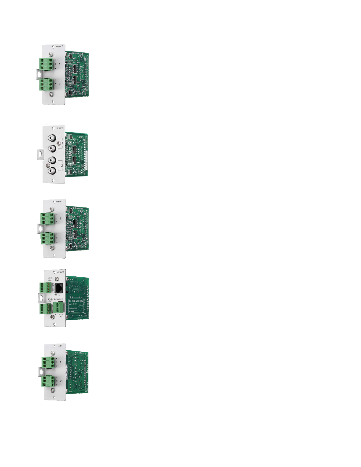
AN-9001 Ambient Noise Sensing Microphone
•Up to 2 may be used with each AN-001T module
•Omni-directional condenser type mic element
•24VDC phantom power operation (provided by AN-001T)
•Single-gang box for easy mounting
•Removable 3-wire phoenix connector
•Low-profile, easily removable cover plate
•Each of up to (4) AN-9001s may be assigned to sense/control a
separate zone or several may be assigned to control a single
zone.
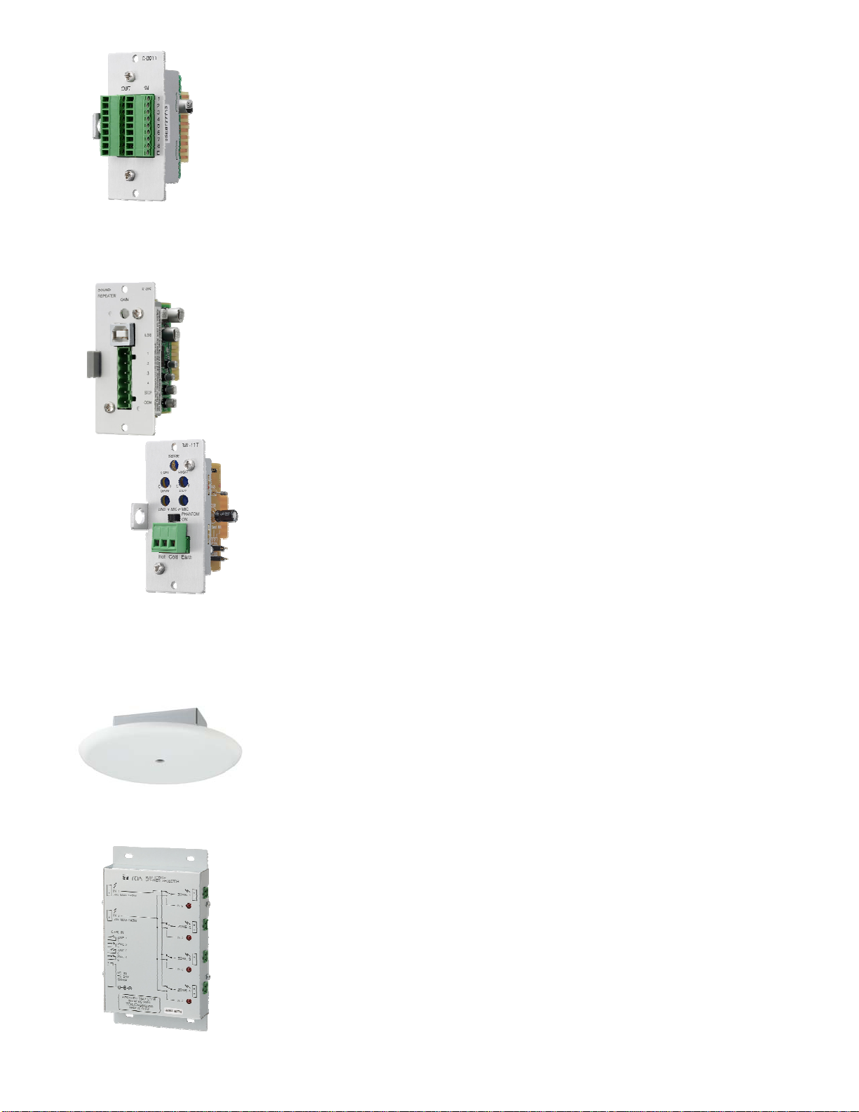
SS-9001 Speaker Selector
•Switch up to four speaker lines on one amplifier output
•Two amplifier inputs for Paging/BGM applications
•Triggered by ZP-001T module control outputs
•Wall-mountable case
•Requires optional 24VDC power supply, model AD-246
8

d. Which Modules Go Where?
C-001T 900 T-001T 900 ZP-001T AN-001T D-001R D-001T
9
8 7 6 5 4 3 2 1
First open Slot after ALL others:
•C-001T
•Max of X
Slot 8: C-001T only
Slots 5-7:
•T-001T (ALWAYS starting from Slot # 5)
•Max of Z
•900 Series (After 9000 Series)
•Up to
[(output & special modules only)
Slots 1-4:
•D-001T
•Max of
[
•D-001R
•Max of
[
•AN-001T
•Max of
Y
•ZP-001T (after D / R / AN)
•Max of
X
•900 Series (after 9000 Series)
•Up to [(Input & special modules only) L
•Either D or AN modules may be ordered in
any way starting from Slot 1-up to four total

LUp to (4) S-20S message repeater modules may be loaded into current versions of
the 9000 Series. However, some earlier version will only support two. Please contact
product support if you are not certain of which production version 9000 unit you have.
L“D” modules should be grouped together and not alternated with “AN”
modules. The best way to determine module slot configuration is to use
the 9000 series GUI Software on your PC. The software will not permit
“illegal” module configurations.
900 Series Modules: The following 900 Series modules are available and will
work in the 9000 Series Module Slots. Please refer to the 900 Series Module
Guide for more detail:
•Input: Mic- ML-11T, M-01S/F/M/P, M11S, M-41S, M-51S/F, M-61S/F, M-
03P, M-21S
•Input: Line-ML-11T, B-01S/F, L-01S/F, U-01S/F, U-01P/R, U-03S/R, B11S,
L-11S, U-11S/R, U-12S, U-13S/R, U-14R, B-21S, U-21S, B-41S, L-41S, U-
43S/R, U61S
•Line Output-T-01S, T-02S, T-12S
•Special: S-01S, S-02S, S-04S, S-20S, V-01S (*E Series equalizer modules
are not required, since the 9000 Series outputs include the EQ for these
speakers).
10

e. What DSP functions are available in each module?
Below is a block diagram of the Input/Output DSP Functions:
11
VOLUME SETTINGS PAGE
EQ SETTINGS PAGE
COMPRESSOR PAGE DELAY SETTING PAGE EQ SETTINGS PAGE
OUTPUT
CHANNEL
MIXER MODE
ONLY
OUTPUT CHANNEL
ONLY
FADER
LInput/Output Channel and Control DSP functions are contained within
the module hardware itself and are not available unless these modules are
installed in the 9000 Series Frame: D-001T, D-001R, T-001T, C-001T. The
9000 Series Mainframe includes 2 channels of Output DSP. The above
DSP functions are NOT available for AN-001T, ZP-001T or 900 Series
modules.

f. When do I need to use this module?
oD-001T: When connecting 1 or 2 balanced mic or line input sources.
oD-001R: When connecting 1 or 2 unbalanced line sources. Channel 1 or Channel
2 – 2 x RCA connectors provide stereo signal summing. Or use one RCA
connector from Channel 1 and one RCA connector from Channel 2 for Stereo Input.
oAN-001T: When using 1 or 2 AN-9001 sensing mics for Ambient Noise Control
oZP-001T: When interfacing with a telephone analog extension port (FXS) (Ring
Signal Mode), to allow using a phone extension as a paging source or to a
standard line level audio output of the telephone system which passes DTMF
signals with a contact closure output (Paging Port Mode).
–NOTE: If there is a standard line level audio output from telephone system which
does not pass DTMF, or does not have the contact closure output, we would
instead recommend using a D-001T module with the input set to VOX.
oT-001T: When connecting to 3 or more external amplifiers (the base 9000 unit has
at least 2 outputs, either 2- line outs, 2- powered outputs or one of each).
oC-001T: When connecting to 5 or more contact-closure ins or outs (the base 9000
Series unit has a compliment of 4 contact closure ins & outs).
o900 Series: When a special function (i.e.-message repeater, tone generator) or
only simple operation is required (input w/volume control). These also work in a
pinch when a 9000 Series module is not available.
g. What if I Need More Inputs/Outputs?
•The input/output configuration on the 9000 Series may be expanded to a full
compliment of 8 Inputs (4 modules) x 8 Outputs (3 modules, plus built-in 1&2). If
the application requires more than this, you have a few options:
a. Although 9000 units cannot be truly “cascaded”, the outputs of one may be
“subbed” into the inputs of another unit. It’s also possible to set
programming via contact in/out so that memory change and other functions
may operate in sync.
b. Depending on the application, the inputs or outputs of multiple 9000s may
be able to operate independently (negating the need for running in tandem).
For example: when running independent paging or BGM sources to isolated
zones. Beyond this, there may simply be a need for a larger mixer (check
out the TOA D-901).
h. What are the PRE OUT & AMP in connections used for?
These are used as a “loop” in/out and allow connection of external
processing equipment (such as an equalizer, compressor or feedback
suppressor). Of course, the good news is the 9000 Series is equipped with an
ample amount of on-board processing. However, in the event you require some
piece of outboard gear to patch in between the preamp and power amp sections,
these loops (also referred to as “inserts”) are provided on the powered models.
There are 2 channels of in/out loops on the dual powered versions-A-9060DH,
A-9120DH & A-9120DL, and a single loop in/out on the A-9060S, A-9120S & A-
9240SH.
12

2. Getting Around the Front Panel Controls
a. What do these buttons and knobs do?
13
12
11
10
98
7
6
4
3 5
2
1
1. Input Select 1-8: Selects the input channel to be controlled from either INPUT
VOLUME and ON/OFF controls or channel to be edited from the menu. These are
also used to enter the 4-digit security password for accessing locked areas.
2. Input Volume: Controls the volume of the selected input channel
3. Input On/Off: Turns the selected input channel ON or OFF
4. Output On/Off: Turns the selected output channel ON or OFF
5. Output Select: Selects the output channel to be controlled from either OUTPUT
VOLUME and ON/OFF controls or the output channel to be edited from the menu.
Pressing repeatedly toggles through the available output channels.
6. Output Volume: Controls the volume of the selected output channel
7. Memory: Selects the memory page to access memories to be recalled, saved or
deleted.
8. Enter: Verifies the current write or recall mode, such as “INITIALIZE MEMORY”,
“MEMORY RECALL”, “SAVE CHANGES”, “ETC…”
9. Parameter: Varies the value of the selected parameter
10. Utility: Accesses the UTILITY menu, which controls various global settings.
11. Esc/Back: Reverts back to the previous menu page (v3.13 firmware & higher) or
escape to normal mode (v3.20 firmware and higher).
12. S/T/W/X: Navigation controls for accessing menu pages, parameters and
characters for naming.
13. Power: Turns power to the unit on or off. When power is “Off” and the unit is still
plugged into a live power source, the unit is in “Standby”, from which it can perform
various remote power on/off functions.
b. What do the indications on the display mean?
KEYLOCK
EMERGENCY
TONE GATE
DELAY COMP
LOUD DUCK
NOM EQ
5
4
3
2
COM
FAULT
1
13

1. Alpha-numeric Display (left side of “:”): Indicates Channel/Preset/Parameter
Name. The COM indicator remains lit during communications via the RS-232C
interface. The FAULT indicator lights when unit failure or other abnormal
conditions have been detected.
2. Input Level Meters: Indicates the input signal level to each channel. Only channels
which have corresponding 9000 Series modules installed will display levels. 900
Series modules and ZP-001T modules do not show input level. Pressing the down
arrow on the navigation controls (when not in the edit menu) switches the display to
show fader level marks. Adjusting the input channel’s level control will change the
fader level, but not the input level. Only adjusting the source level or input sensitivity
level will change the input level reading. A red LED next to the channel number
indicates the channel which is selected for adjustment. A blinking channel number
indicates that channel is muted (off).
3. Output Level Meters: Indicates the signal level to each output channel. Pressing
the down arrow on the navigation controls (when not in the edit menu) switches the
display to show fader level marks. Adjusting the output channel’s level control will
change the fader level, but not signal level. Only changing the level of input channels
routed to that output will affect the output’s signal level reading. A red LED next to the
output channel number indicates the channel which is selected for adjustment. A
blinking channel number indicates that output channel is muted (off). Only channels
which have corresponding 9000 series modules installed, in addition to the 9000
Mainframe output channels will show a number or have a meter display reading.
4. Alpha-numeric Display (right side of “:”): Indicates the currently selected
parameter’s value or channel’s status. A unit display to the right indicates units (dB,
Hz, kHz, mSec) of the displayed value.
5. Indicates which effects are activated for the selected channels. Each one blinks
when being edited.
c. How do I edit from the front panel…..
I. In Mixer Mode?
i , j
h
f
e
d, g b
a, c
a
a. Working within the currently active memory preset (scene), when an input or output
channel has been selected, pressing the “X” arrow on the navigation controls enters
the edit menu.
b. Using the “S/T” arrows scrolls through the parameters for that input or output
channel (parameters may vary depending on the module installed).
14

c. Pressing the “X” again highlight the parameter value portion of the menu. Once a
specific parameter has been selected, another channel may also be selected for
adjustment of that same parameter (assuming similar module type).
d. Adjusting the Parameter Knob changes the value of the selected parameter.
e. Pressing the “ESC/BACK” key reverts to the previous edit page or escapes the edit
menu.
f. Pressing the “MEMORY” button accesses the preset memory register.
g. Adjusting the PARAMETER” knob selects the memory slot to be used.
h. Pressing “ENTER” stores the current settings to that scene.
i. Pressing the “UTILITY” button accesses the utility menu, where global or special
functions may be edited. These settings are not stored with presets, but with
configuration templates.
j. The Utility menu is navigated the same way as the main edit menu, but to escape,
press the “MEMORY” button and any channel button.
II. In Matrix Mode?
c
d
a, e
b. (blank screen)
b
a. To enter, delete the display indication by pressing the MEMORY key (screen goes
blank),
b. Then holding down the UTILITY menu key for 2 seconds or more displays the
setting menu screen.
Note: You cannot enter the setting mode as long as any indication is displayed in
the upper line of the VFD screen.
c. Then, using the navigation keys (S/T/W/X), items may be selected in the display
Examples of using the Left and Right arrow keys:
When moving the setting screen:
SELECT INPUT CH
INPUT-SETTING
15

When moving the setting item on the same screen:
16
Example of using the Up and Down arrows:
When accessing parameter or item pages within the settings menu:
HPF - 400HZ LPF – 12.5
IN 1 – INPUT 1
HPF - 400HZ LPF – 12.5
IN 1 PRIORITY 8
d. Returning to NORMAL operation: Press the ESCAPE/BACK key when the
setting screen returns the display to the setting start screen (upper hierarchy level).
e. Pressing the MEMORY key at the setting menu screen saves the setting contents
and returns the display to the normal use state.
d. How do I program an Event in Matrix Mode from the front panel?
Programming EVENTS in Matrix Mode is broken down to essentially four parameters:
INPUT SELECT, EVENT TYPE, TRIGGER & OUTPUT ASSIGNMENT. Here is the
procedure for EVENT settings:
1. Hold UTILITY button 3-5 Seconds
2. Then rotate PARAMETER knob to EVENT-SETTING.
3. Press the RIGHT ARROW to EVENT01 (01 Flashing): NONE
4. Then press the RIGHT ARROW TO EVENT01: NONE (NONE Flashing).
5. Rotate PARAMETER knob to ROUTE.
6. Press the DOWN ARROW and select INPUT# using the PARAMETER knob (or INPUT
SELECT button),
7. Press the DOWN ARROW and select the OUTPUT# using the PARAMETER knob,
8. Then press the ON/OFF button (above the OUTPUT SEL button) to turn on a RED LED
next to the appropriate OUTPUT# channel indicator on the display.
9. Press the DOWN ARROW and select the TRIGGER IN using the PARAMETER knob
10. Press the RIGHT ARROW to the TRIGGER IN # and select a trigger in using the PARAMETER
knob.
11. Follow steps d & eabove to escape the EVENT SETTING menu.

17
(Please reference the next section on “Operating Modes” to gain a better
understanding of how to use Events in Matrix mode)
3. Operating Modes:
a. What are the two different operating modes best used for?
•Mixer Mode: Best used for general mixing applications-i.e.-conference rooms,
bar/restaurant, retail spaces, etc… Typically, this is for basic paging over background
music or live source mixing (such as microphones). The Mixer Mode may also be used for
room combining applications. Mixer mode operates with the condition that the
environment does not change while a given scene is active. A scene change could
encompass ALL sources and settings for a given time and remain in that state until the
environment requires a scene change. So, in a room combing scenario: Scene 1: room 1
& room 2 are set as independent. Scene 2: room 1 & room 2 are combined for one event.
Switching between these two “snapshots” scenes will allow the room combining switch to
be made smoothly. However, if the two rooms do not operate in sync, then it’s a job for….
•Matrix Mode: Matrix Mode allows the independent orchestration of individual sources or
“events” which may be broadcast simultaneously. As opposed to a global “scene” change
memory (as in Mixer mode), where everything changes at once, Matrix mode allows each
input source to be “activated" independently from all the others. This provides a mixing
environment where each source stands alone and where any source brought on-line will
not necessarily interfere with or affect any other source being routed at the same time.
This is useful for multi-zone paging and where requirements change at different times.
b. How does operation of these two modes differ?
Here are some examples of how each mode would operate (these are based on a full 8 x 8
configuration):
Mixer: Each SCENE memory would contain all input/output settings and routing and can only
be recalled one at a time. Also note that multiple inputs are routed to one or more output (as
denoted by the color group).
Scene 1:
Output 1 Output 2 Output 3 Output 4 Output 5 Output 6 Output 7 Output 8
Input 1
BGM
Input 2
PAGE
Input 3
BGM
Input 4
BGM
Input 5
PAGE
Input 6
BGM
Input 7
MIC
Input 8
MIC

Scene 2:
Output 1 Output 2 Output 3 Output 4 Output 5 Output 6 Output 7 Output 8
Input 1
BGM
Input 2
PAGE
Input 3
BGM
Input 4
BGM
Input 5
PAGE
Input 6
BGM
Input 7
MIC
Input 8
MIC
Matrix: Each Event preset encompasses only single input routed to one or more outputs.
18
Output 1 Output 2 Output 3 Output 4 Output 5 Output 6 Output 7 Output 8
Input 1
BGM
Input 2
BGM
Input 3
PAGE
Input 4
BGM
Input 5
BGM
Input 6
PAGE
Input 7
PAGE
Input 8
PAGE
Event 1 Event 2 Event 3 Event 4 Event 5 Event 6 Event 7 Event 8
So: *(not shown)
Event 1- Input 1 routed to Outputs 1, 2 & 3 Event 9- Base Event consisting of
Event 2- Input 2 routed to Outs 1, 2 & 3 Events 1, 2, 4 & 5
Event 3- Input 3 routed to Outs 1, 2 & 3 Event 10- BGM End Event –Stops broadcast
Event 4- Input 4 routed to Outs 4, 5 & 6 of all background music sources
Event 5- Input 4 routed to Outs 4, 5 & 6
Event 6- Input 4 routed to Outs 4, 5 & 6
Event 7- Input 4 routed to Out 7
Event 8- Input 4 routed to Outs 1-8
Each of these “events” may be activated independently and simultaneously, by either: voice
or audio input activation (VOX), contact closure or serial control (*See “Controlling the 9000
Series” on pg. 40) or may be active all the time. In effect these sources are being mixed, but
are not activated by a single memory preset. Other than the “ROUTE” events shown above,
other types of events may also be programmed:
*Base Event: Is a collection or set of up to four Route events which may be stored under a
single preset and recalled simultaneously. This type of event may be used to bring several
BGM sources online at one time and also assigned to be the default memory for power on.
*BGM End event: An event memory programmed to discontinue routing of all BGM
(Background Music) sources. This is a fast and convenient way to stop music sources from
playing during an emergency or at end of business.

Below is a comparison description of the two modes:
FEATURE MIXER MATRIX
Memories 32 Scenes 32 Events
Memory Activation Single Simultaneous
Routing per Memory Up to eight inputs to up to eight
outputs One input to up to eight
outputs
Paging Priorities 2 Levels 8 Levels
Other Functions Auto-mixing (gating),
Cross-point Gain, Delay FIFO, LIFO, MIX
LAll input/output settings such as level, EQ, compressor, etc… are stored with each scene
in Mixer Mode. Therefore, each scene may have different channel settings. Matrix Mode stores
routing and control settings for each event and settings for each input are the same for all
events it is associated with. In each case, these are stored along with other global settings to
the .mix or .mtx template.
c. How do I change the 9000 unit’s Operating Mode?
1. With the 9000 unit powered off, unplug the power cord to the back panel or turn off
power to the strip supplying power.
2. Move the MATRIX/MIXER switch on the back to the desired position.
3. Reapply power to the unit.
4. When the display reads “INITIALIZE MEMORY?” press
the ENTER button on the front panel. After initialization,
the 9000 unit will automatically power off.
5. Power the unit back on using the front panel power button.
6. The 9000 unit is now in the new mode. The previous
mode’s memories and setting are now erased and the
unit now will await new programming.
19

d. How do I save Configurations to a PC?
Once a set of SCENE or EVENT memories have been programmed in the GUI or
(EXCEL), these may be saved as configuration files to a PC. The configuration file
contains settings for all 32 memories, including global and control settings and will store
as either an .mtx file (MATRIX file) or .mix (MIXER file). These may be named according
to application or project.
1. File > Save As > [folder] > [name].mtx - or- [name].mix
2. These files may be opened into the GUI software and loaded into the active GUI
screen.
3. From there they may be uploaded to a 9000 unit (see “Communicating with Your
PC”- on page 37)
Similarly, selecting OPEN from the file menu will load a stored template
from your PC to the application. Remember that the application mode
(Matrix/Mixer) must match the template you wish to load.
20
Other manuals for A-9060DH
8
This manual suits for next models
16
Table of contents
Other Toa Amplifier manuals