OPTION
Unit: mm
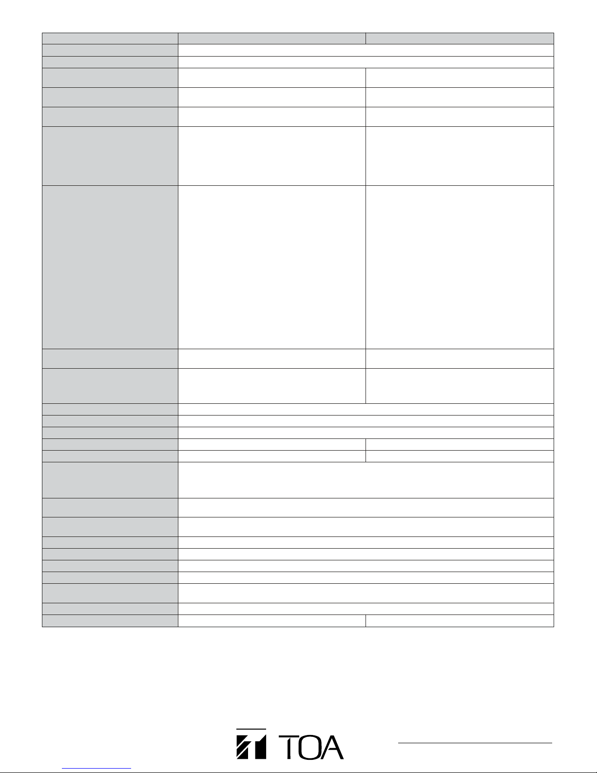
MT-251H
•Capacity: 0W – 250W
•Primary Side: 100V line, 70V line
•Secondary Side: 100V line, 70V line, 50V line, 35V line
•Frequency Response: 30 – 18,000Hz (+0dB, –3dB)
•Connection Terminal: M3 screw terminal, distance between barriers: 6.6mm (0.26")
•Dimensions: 108 (W) ×80 (H) ×122 (D)mm (4.25" ×3.15" ×4.80")
•Weight: 2.4kg (5.29 lb)
Max. 80 (Max. 3.15")
4–5X7 (0.2" X 0.28")
97 (3.82")
108 (4.25")
66 (2.6")
94 (3.7")
122 (4.8")
Front View Side View
Matching Transformer
Designed for use with the DA-250DH Dual-Channel Power
Amplifier (option), the MT-251H electrically isolates the high-
impedance speaker lines from the amplifier.
DA-250D SPECIFICATIONS
The dual-channel power amplifier shall use class-D circuit topology and
shall be configurable to two channel operation. Power output in wo-
channel mode with all channels driven shall be: 250W per channel into 4
ohms and 170W per channel into 8 ohms. Each pair of channels shall be
bridgeable to produce 500 W. Total harmonic distortion (THD) shall be
less than 0.1% @ 1 kHz, 0.3 % (20 to 20,000 Hz). The frequency response
shall be 20 to 20,000 Hz (±1 dB). The signal to noise ratio shall be 100 dB
(A-weighted). The crosstalk shall be 70 dB (A-weighted). The input
impedance shall be 10k ohms for each input into an electronically
balanced input circuit. Rear panel switches shall allow selection of
bridged operation for 1-2 channels. A rear channel input mode switch
shall allow the selection of input 1 to all mode, whereby the signal from
input 1 is simultaneously fed to other channel. Each input shall feature a 3
pin phoenix block and XLR connector. Rear panel output connector shall
be a heavy-gauge M4 screw-terminal barrier strip suitable for use with
spade lugs or up to #12 AWG bare wires. The front panel attenuators shall
be recessed to prevent accidental level changes and may be removed
and replaced by included security covers once levels have been properly
set. The front panel shall have two sets of four LED indicators to indicate
the following conditions: signal presence at input (greater than -20 dB),
signal presence at output (greater than 1 W @ 8 ohms load), peak clipping
and protection circuit activation. The front panel shall also have two
removable air filters that may be removed for cleaning without removing
the amplifier from the rack. The amplifier shall be forced-air fan cooled
with the air intake at the front and exhaust at the rear.
Built-in protection circuitry shall monitor voltage and current levels to
minimize potential damage from overloads, and disable output during
shorts, DC offset, or excessive operating temperature at power amp heat
sink over 212°F (100°C), or excessive operating temperature inside the
unit over 176°F (80°C) via a relay for each channel. The relay shall also
delay amplifier connection to the load during turn-on for about 2 seconds,
so as to prevent any occurrence of noise at turn-on. Power consumption
shall be 120 W (based on UL/CSA standards) and 650 W (rated output 4
ohms x 2 channels), and 420 W (rated output at 8 ohms x 2 channels).
The amplifier shall use only one standard rack-spaces or 1.75" (44.5 mm)
and its dimensions shall be 18.98" (W) x 1.73" (H) x 15.82" (D) (482 x 44 x
401.8 mm). Front panel finish shall be black anodized aluminum and case
finish shall be sheet steel. Weight shall be 11.02 lb (5 kg).
The amplifier shall be a TOA model DA-250D.
DA-250DH SPECIFICATIONS
The dual-channel power amplifier shall use class-D circuit topology and
shall be configurable to two channel operation. Power output in two-
channel mode with all channels driven shall be: 250W per channel into
19.6 ohms (70V). A pair of channels shall be bridgeable to produce 500W
into 39.2 ohms (140V). Total harmonic distortion (THD) shall be less than
0.1% @ 1 kHz, 0.3 % (20 to 20,000 Hz) HPF OFF, and 0.3 % (100 to
20,000 Hz) HPF ON. The frequency response shall be 50 to 20,000 Hz (-3
dB, +1 dB) HPF ON. The frequency response shall be 20 to 20,000 Hz (±1
dB) HPF OFF. The signal to noise ratio shall be 100 dB (A-weighted).
The crosstalk shall be 70 dB (A-weighted). The input impedance shall be
10k ohms for each input into an electronically balanced input circuit. Rear-
panel switch shall allow selection of bridged operation. The amplifier shall
operate in 2-channel mode when the switch is deselected.
A rear-panel input mode switch shall allow the selection of input 1 to all
mode, whereby the signal from input 1 is simultaneously fed to the other
channel. Each input shall feature a 3 pin phoenix block and XLR
connector. Rear panel output connector shall be a heavy-gauge M4
screw-terminal barrier strip suitable for use with spade lugs or up to #12
AWG bare wires.
The front panel attenuators shall be recessed to prevent accidental level
changes and may be removed and replaced by included security covers
once levels have been properly set. A dip switch on the rear of the unit
shall allow independent on/off selection of a 50 Hz (-6 dB/Oct) high-pass
filter (HPF) cut-off for protection against excessive low frequency loading
and saturation of speaker transformers.
The front panel shall have two sets of four LED indicators to indicate the
following conditions: signal presence at input (greater than -20 dB), signal
presence at output (greater than 1 W @ 19.6 ohms load), peak clipping,
and protection circuit activation. The front panel shall also have two
removable air filters that may be removed for cleaning without removing
the amplifier from the rack. The amplifier shall be forced-air fan cooled
with the air intake at the front and exhaust at the rear.
Built-in protection circuitry shall monitor voltage and current levels to
minimize potential damage from overloads and disable output during
shorts, DC offset or excessive operating temperatur at power supply heat
sink over 212°F (100°C) or excessive operating temperature inside the
unit over 176°F (80°C) via a relay for each channel. The relay shall also
delay amplifier connection to the load during turn-on for about 2 seconds,
so as to prevent any occurrence of noise at turn-on. Power consumption
shall be 120 W (based on UL/CSA standards) and 580W (rated output
19.6 ohms x 2 channels).
The amplifier shall use only one standard rack-space or 1.75" (44.5m) and
its dimensions shall be 18.98" (W) x 1.73" (H) x 15.82" (D) (482 x 44 x
401.8 mm). Front panel finish shall be black anodized aluminum and
case finish shall be sheet steel. Weight shall be 11.02 lb (5 kg).
The amplifier shall be a TOA model DA-250DH.
The optimal 1:1 line isolation transformer shall be TOA model MT-251H.
ARCHITECTURAL AND ENGINEERING SPECIFICATIONS