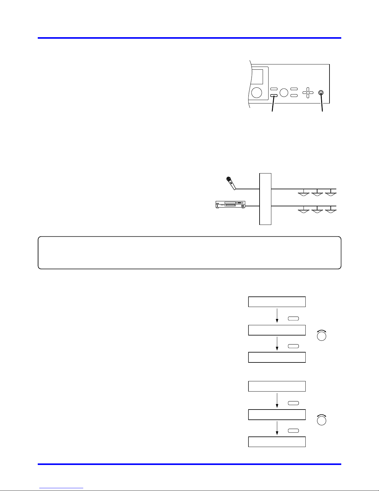
Install modules based on the following guide.
• From right to left - Do not skip otherwise described.
• Follow the steps described below.
Step 1. Install 9000 series input modules from D-001T.
... D-001T AN-001T
Step 2. Install 9000 series output modules.
... T-001T
Note
Output modules should be installed from 5th slot
from right.
Step 3. Install 9000 series other audio interface modules.
... ZP-001T
Step 4. Install non-9000 series modules.
... Legacy 900 series modules
Step 5. Install non-audio modules.
... C-001T
Notes
• Be sure to install the needed modules in the proper slots before programming the unit, as changing the quantity or location
of any modules will force the unit to erase all stored settings.
• Disconnect the AC power cord before proceeding.
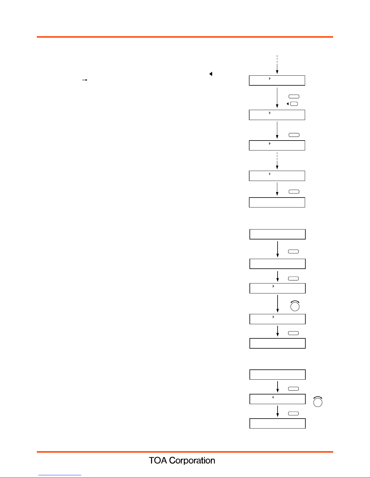
MIXER mode
This mode allows for full matrix mixing of any desired inputs
to any desired outputs in the desired amounts. -- especially
for background music systems, AV systems, room-
combining systems, or systems using several microphones.
You can also add one level of priority for basic paging
functionality. The operator can make fine adjustments to the
mix in real time while actually monitoring sound output. Up to
32 scene memories may be pre-set and recalled, storing all
parameters including routing, EQ and volume settings.
MIXER mode also provides automatic mixing (using the gate
and NOM attenuation functions), selectable channel-
grouping (for stereo operation), and zone-selectable priority
paging with variable ducking level.
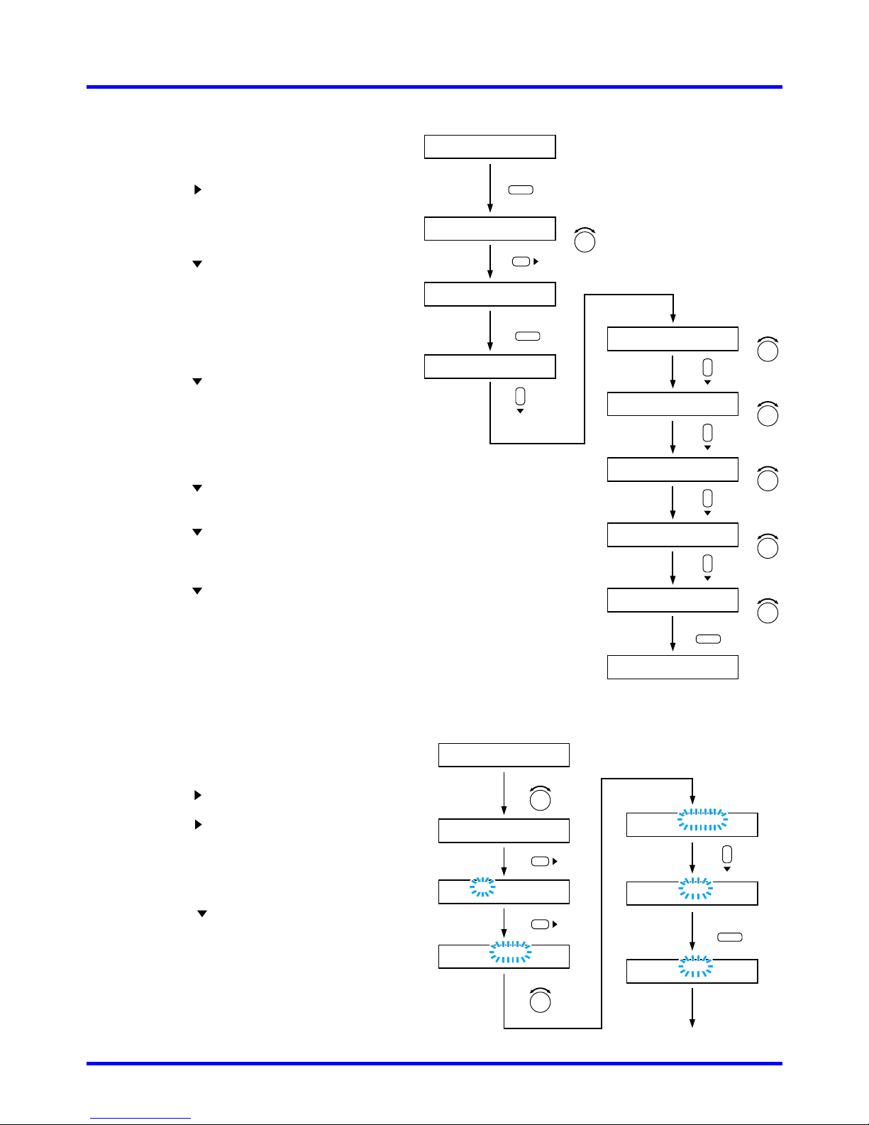
MATRIX mode
This mode is recommended for zone paging and
paging with background music using muting priorities.
It provides 8 levels of priority, with selection of First-In-
First-Out, Last-In-First-Out or mixing for inputs sharing
the same priority level. Event-based programming
allows complex input-to-output assignments to be
quickly changed, based on a VOX trigger or remote
contact closure, without altering volume or EQ
adjustments.
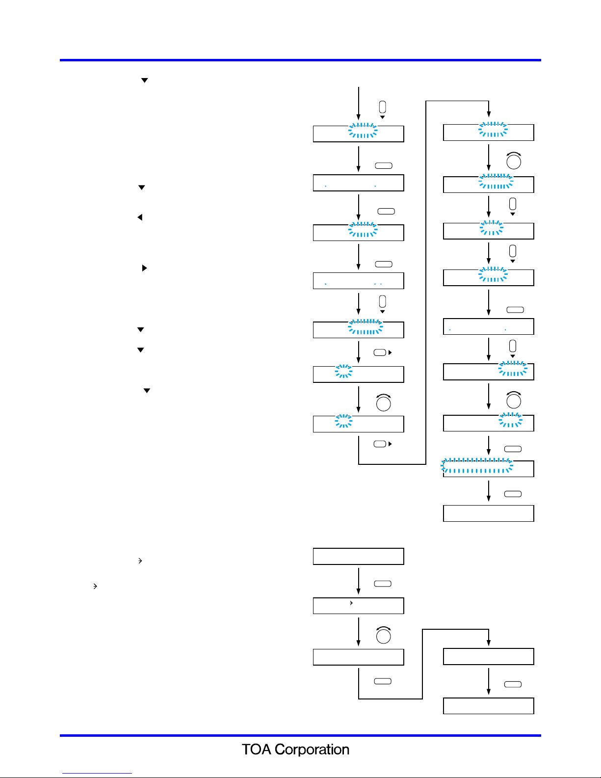
MATRIX mode is recommended for advanced paging
systems having complex dynamic routing
requirements, systems using multiple priority levels,
and jobs with special routing control requirements.
Continue to the following.Refer to separate "9000 series amplifiers
Quick start guide –MIXER MODE."