3
2. SAFETY PRECAUTIONS
•
Before installation or use, be sure to carefully read all the instructions in this section for correct and safe
operation.
• Be sure to follow all the precautionary instructions in this section, which contain important warnings and/or
cautions regarding safety.
• After reading, keep this manual handy for future reference.
Safety Symbol and Message Conventions
Safety symbols and messages described below are used in this manual to prevent bodily injury and property
damage which could result from mishandling. Before operating your product, read this manual first and
understand the safety symbols and messages so you are thoroughly aware of the potential safety hazards.
When Installing the Unit
• Do not expose the unit to rain or an environment
where it may be splashed by water or other liquids,
as doing so may result in fire or electric shock.
• Ne pas exposer l'appareil à la pluie et le protéger
de tout contact avec de l'eau ou d'autres liquides
afin d'éviter un incendie ou une électrocution.
• Use the unit only with the voltage specified on the
unit. Using a voltage higher than that which is
specified may result in fire or electric shock.
• Do not cut, kink, otherwise damage nor modify the
power supply cord. In addition, avoid using the
power cord in close proximity to heaters, and never
place heavy objects -- including the unit itself -- on
the power cord, as doing so may result in fire or
electric shock.
• Since the unit is designed for indoor use, do not
install it outdoors. If installed outdoors, the aging of
parts causes the unit to fall off, resulting in personal
injury. Also, when it gets wet with rain, there is a
danger of electric shock.
• The apparatus shall be connected to a mains
socket outlet with a protective earthing connection.
• L'appareil doit être branché à une prise
d'alimentation avec mise à la terre de protection.
• The socket-outlet shall be installed near the
equipment and the plug shall be easily accessible.
• La prise doit être installée à proximité de
l'équipement et la fiche doit être facilement
accessible.
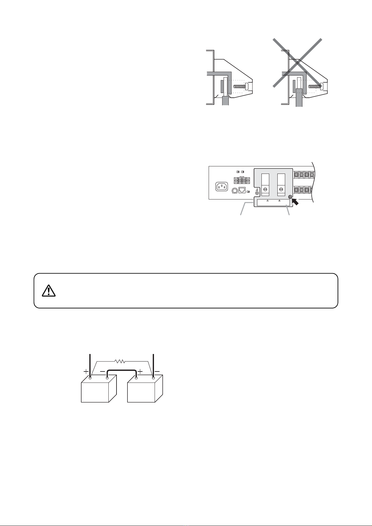
•
External wiring connected to the terminals marked
with requires installation by an instructed person.
When the Unit is in Use
• Should the following irregularity be found during
use, immediately switch off the main power (or
circuit breaker), disconnect the battery, and contact
your nearest TOA dealer. Make no further attempt
to operate the unit in this condition as this may
cause fire or electric shock.
· If you detect smoke or a strange smell coming
from the unit.
· If water or any metallic object gets into the unit
· If the unit falls, or the unit case breaks
· If the power supply cord is damaged (exposure of
the core, disconnection, etc.)
· If it is malfunctioning (no tone sounds.)
• To prevent a fire or electric shock, never open the
unit case nor modify the unit. Refer all servicing to
qualified service personnel.
• Do not place cups, bowls, or other containers of
liquid or metallic objects on top of the unit. If they
accidentally spill into the unit, this may cause a fire
or electric shock.
• Ne pas placer de tasses, bols ou autres récipients
remplis de liquides ou d'objets métalliques au-
dessus de l'appareil. S'ils se répandent par
accident sur l'appareil, ils peuvent provoquer un
incendie ou une électrocution.
• Do not insert nor drop metallic objects or
flammable materials in the ventilation slots of the
unit's cover as this may result in fire or electric
shock.
• Do not touch a power supply plug during thunder
and lightning, as this may result in electric shock.
• Handle or use the batteries properly.
Doing otherwise may cause leakage or explosion
of the batteries, resulting in a fire, personal injury,
damage to peripheral equipment, or contamination
of environment.
WARNING
Indicates a potentially hazardous situation
which, if mishandled, could result in death or
serious personal injury.
AVERTISSEMENT
Indique une situation risquant d’entraîner des
blessures graves, voire la mort, en cas de
mauvaise manipulation.