Toa C-RF1000 Parts list manual

INTERFACE UNIT C-RF1000
REMOTE CONTROLLER
POWER/DVR4321
INTERFACE UNIT C-RF1000
OPERATING INSTRUCTIONS
1. SAFETY PRECAUTIONS .......................... 2
2. GENERAL DESCRIPTION ........................ 3
3. FEATURES ................................................ 3
4. HANDLING PRECAUTIONS ..................... 3
5. NOMENCLATURE AND FUNCTIONS
Front panel .................................................. 4
Rear panel................................................... 4
6. CONNECTIONS
6.1. System Example .................................. 5
6.2. About connections ................................ 6
6.2.1. When connecting the C-RF1000
to the Remote controller or PC ......... 6
6.2.2. When connecting the C-RF1000
to the Digital Video Recorder ............. 6
7. RACK MOUNTING ..................................... 7
8. SPECIFICATIONS ...................................... 8
Accessory .................................................... 8
Thank you for purchasing TOA's Interface Unit. Please carefully follow the instructions in this manual to
ensure long, trouble-free use of your equipment.
TABLE OF CONTENTS

2
1. SAFETY PRECAUTIONS
• Before installation or use, be sure to carefully read all the instructions in this section for correct and safe
operation.
• Make sure to observe the instructions in this manual as the conventions of safety symbols and messages
regarded as very important precautions are included.
• We also recommend you keep this instruction manual handy for future reference.
Safety Symbol and Message Conventions
• Safety symbols and messages described below are used in this manual to prevent bodily injury and property
damage which could result from mishandling. Before operating your product, read this manual first and
understand the safety symbols and messages so you are thoroughly aware of the potential safety hazards.
Indicates a potentially hazardous situation which, if mishandled, could
result in death or serious personal injury.
WARNING
When Installing the Unit
• This is a class A product. In a domestic environment this product may cause radio interference in which case
the user may be required to take adequate measures.
• Avoid installing or mounting the unit in unstable locations, such as on a rickety table or a slanted surface.
Doing so may result in the unit falling down and causing personal injury and/or property damage.
When the Unit is in Use
• If any of the following irregularities occurs, immediately switch off the power, disconnect the power supply
plug from the AC outlet and inform the shop from where the unit was purchased. Further using the unit may
result in fire or electric shock.
· If you detect smoke or a strange smell coming from the unit
· If water or any metallic object gets into the unit
· If the unit falls, or the unit case breaks
• To prevent a fire or electric shock, never open the unit case nor modify the unit as there are high voltage
components inside the unit. Refer all servicing to your nearest TOA dealer.
• Do not place cups, bowls, or other containers of liquid or metallic objects on top of the unit. If they
accidentally spill into the unit, this may cause a fire or electric shock.
• Do not insert nor drop metallic objects or flammable materials in the ventilation slots of the unit's cover, as
this may result in fire or electric shock.
• Do not touch the control line during thunder and lightning, as this may result in electric shock.
• Avoid using the unit in close proximity to medical equipment, as the electromagnetic field generated by the
unit could adversely affect the operation of sensitive medical equipment.
Do not expose the unit to rain or an environment where it may be
splashed by water or other liquids, as doing so may result in fire or
electric shock.
WARNING

3
When Installing the Unit
• Avoid installing the unit in humid or dusty locations, in locations exposed to the direct sunlight, near the
heaters, or in locations generating sooty smoke or steam as doing otherwise may result in fire or electric
shock.
• Do not connect a network terminal exposed to excessive voltage to the DVR connection terminal, as doing
so may result in fire or electric shock.
• Do not connect the DVR Control Output Terminal A (RJ-11) to networks that could be exposed to excessive
electrical voltage. Failure to follow this instruction could result in electric shock or fire.
When the Unit is in Use
• Do not place heavy objects on the unit as this may cause it to fall or break which may result in personal
injury and/or property damage.
• Clean the unit periodically. Contact your TOA dealer regarding the cleaning. If dust is allowed to accumulate
in the unit over a long period of time, a fire may result.
Indicates a potentially hazardous situation which, if mishandled, could
result in moderate or minor personal injury, and/or property damage.
CAUTION
Note
This equipment has been tested and found to comply with the limits for a Class A digital device,
pursuant to Part 15 of the FCC Rules. These limits are designed to provide reasonable protection
against harmful interference when the equipment is operated in a commercial environment. This
equipment generates, uses, and can radiate radio frequency energy and, if not installed and used in
accordance with the instruction manual, may cause harmful interference to radio communications.
Operation of this equipment in a residential area is likely to cause harmful interference in which case the
user will be required to correct the interference at his own expense.
Modifications
Any modifications made to this device that are not approved by TOA Corporation may void the authority
granted to the user by the FCC to operate this equipment.
CU version complies with Part 15 of the FCC Rules.
2. GENERAL DESCRIPTION
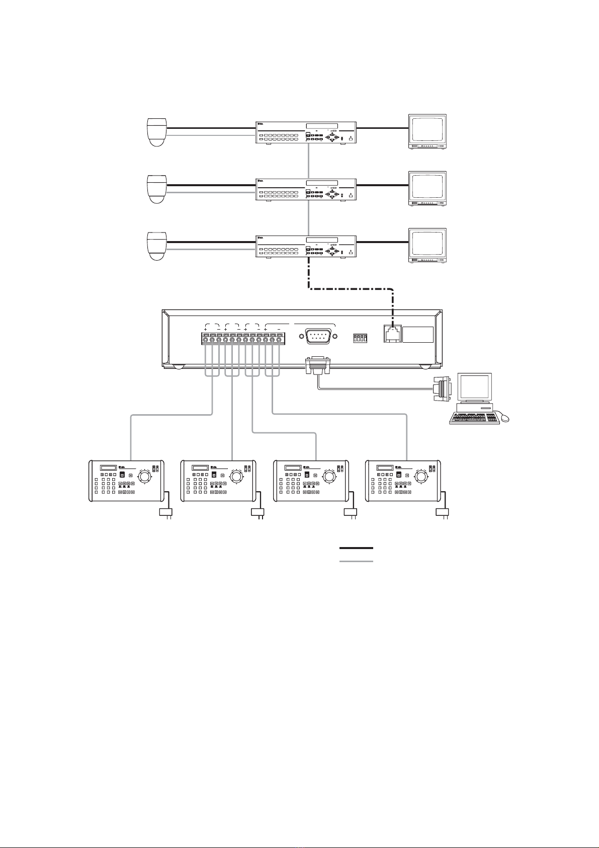
The C-RF1000 Interface Unit is used to expand the C-RM1000 Remote Controller when using 2 to 4 Remote
Controllers to operate the C-DR091 or C-DR161 Series Digital Video Recorder.
3. FEATURES
• Up to 4 C-RM1000 Remote Controllers can be connected.
• The Unit's RS-232C port permits control of the Digital Video Recorder. (Multiple Digital Video Recorders can
also be connected in cascade and controlled, unlike the Digital Video Recorder's RS-232C port.)
4. HANDLING PRECAUTIONS
• Power is supplied from the Digital Video Recorder if the C-RF1000 is connected to the Digital Video
Recorder using the supplied modular cable.
• Do not connect the DVR Control Output Terminal A (RJ-11) to the telephone line.
• When two or more remote controllers are operated simultaneously, operational delay or error may occur. In
such cases, operate the remote controller after waiting for a few seconds.

4
(1) Power Indicator [ POWER/DVR ]
Lights when power is supplied from the Digital
Video Recorder, and flashes during communi-
cations with the Digital Video Recorder.
(2) Remote Controller Communications Indicator
[ 1 - 4 ]
Flashes when the Remote Controller input
terminal receives a signal. Indicator 4 also
flashes when the RS-232C port receives a
signal.
[ Rear panel ]
OFF
ON 4321
OUTPUT-A
DVR CONTROLRS-232CREMOTE CONTROLLER INPUT-B
4
GND
3
GND
2
GND
1
GND
Do not connect
this jack to
telephone line.
56
34
(3) Remote Controller Input Terminal B
Used to connect the Remote Controller to the
Interface Unit. Remote Controller Input Terminal
4 cannot be used simultaneously with the RS-
232C port.
(4) RS-232C Port [ RS-232C ]
Connect this port to a PC's RS-232C port to
control cascade-connected Digital Video
Recorders from the PC. This port cannot be used
simultaneously with Remote Controller Input
Terminal 4.
(5) DIP Switch
Sets the transmission rate of both the Remote
Controller input terminal and RS-232C port.
Note: Factory-preset to "38,400 bps."
(6) DVR Control Output Terminal A (RJ-11)
Outputs signals transmitted from the Remote
Controller input terminal or RS-232C port to the
Digital Video Recorder. Power is supplied from
the Digital Video Recorder when this terminal is
connected to the Digital Video Recorder.
Note
The transmission rate of this terminal is fixed to
38,400 bps regardless of DIP switch settings. Set
remote controller's bit rate of the Digital Video
Recorder to be connected to 38,400 bps.
REMOTE CONTROLLER
POWER/DVR4321
INTERFACE UNIT C-RF1000
12
5. NOMENCLATURE AND FUNCTIONS
[ Front panel ]
Transfer speed
1
38,400 bps
19,200 bps
9,600 bps
ON
ON
OFF
2
ON
OFF
ON
34
Not used.
Factory-preset to ON.
DIP switch
[ Bottom Panel ]
TOA Corporation
MADE IN JAPAN
model C-RF1000 CU
INTERFACE UNIT
12V 100mA
SER.

5
Do not connect
this jack to
telephone line.
OFF
ON 4321
OUTPUT-A
DVR CONTROLRS-232CREMOTE CONTROLLER INPUT-B
4
GND
3
GND
2
GND
1
GND
PC
KEYLOCK
DIGITALVIDEO RECORDER C-DR161
HDFULL
FAILURE
REC
16
8
15
7
14
6
13
5
12
4
11
3
10
2
9
1ARCHIVE
KEYLOCK
DIGITALVIDEO RECORDER C-DR161
HDFULL
FAILURE
REC
16
8
15
7
14
6
13
5
12
4
11
3
10
2
9
1ARCHIVE
KEYLOCK
DIGITALVIDEO RECORDER C-DR161
HDFULL
FAILURE
REC
16
8
15
7
14
6
13
5
12
4
11
3
10
2
9
1ARCHIVE
RS-232C
RS-485
RS-485
RS-485
RS-485
RS-485
RS-485 RS-485
RS-485
RS-485
Combination camera Digital Video Recorder
C-DR091 and C-DR161 Series
Monitor
Supplied modular cable (3 m (9.8 ft))
Interface unit
C-RF1000
AC adapter
: CPEV-S 0.65-2C (RS-485 control Line)
Remote controller 1
C-RM1000
Remote controller 2
C-RM1000
Remote controller 3
C-RM1000
Remote controller 4
C-RM1000
: Coaxial cable (Video signal)
6. CONNECTIONS
6.1. System Example
Notes
• Use the CPEV-S cable (twisted pair shielded cable) with diameter larger than 0.65 mm (AWG22) for the RS-
485 control line. Be sure to connect the shielded cable to the GND terminal.
• When two or more remote controllers are operated simultaneously, operational delay or error may occur. In
such cases, operate the remote controller after waiting for a few seconds.
• Remote Controller Input Terminal 4 cannot be used simultaneously with the RS-232C port. Connect either.

6
6.2. ABOUT CONNECTIONS
6.2.1. When connecting the C-RF1000 to the Remote controller or PC
PC
REMOTE CONTROLLER INPUT-B
(Screwless terminal)
RS-232C
*2
*1
1234
The maximum cable length is 1.2 km (3,937 ft) for each distance between
the Remote Controller and the Interface Unit.
Interface unit
C-RF1000
Remote controller 1
Remote controller 1
Remote controller 1
Remote controller 1
Screwless terminal
Screwless terminal
Screwless terminal
Screwless terminal
Notes
*1. Match the transmission rate of all components connected to the Interface Unit. The Interface Unit's DIP
switch settings must also be identical with the Remote Controller's bit rate settings.
*2. Remote Controller Input Terminal 4 cannot be used simultaneously with the RS-232C port. Connect
either.
6.2.2. When connecting the C-RF1000 to the Digital Video Recorder
The maximum cable length is 1.2 km (3,937 ft) for distance between
the Interface Unit and the farthest Digital Video Recorder.
Interface unit
C-RF1000
Screwless
terminal
Screwless
terminal
Screwless
terminal
Screwless
terminal
RJ-11 terminal RJ-11 terminal
Supplied modular cable (3m (9.8 ft))
Supplies the power
Digital Video Recorder Digital Video Recorder Digital Video Recorder
Termination switch: OFF Termination switch: OFF Termination switch: ON
Note
The transmission rate between the Interface Unit and the Digital Video Recorder is fixed to 38,400 bps
regardless of DIP switch settings. Set remote controller's bit rate of all Digital Video Recorders to 38,400 bps.

7
7. RACK MOUNTING
Use the optional mounting bracket to mount the unit in an equipment rack.
When mounting the unit, remove the rubber feet installed on its bottom surface.
To mount the unit in an equipment rack (Use the optional MB-15B-BK Half Width Blank Panel.)
REMOTECONTROLLER
POWER/DVR
4
32
1
INTERFACE UNITC-RF1000
C-RF1000
3 x 14 self tapping screw *
Rack mounting bracket *
M5 fiber washer *
3 x 14 rack mounting screw *
Component/ accessories of the MB-15B-BK
*
Blank panel *
3 x 14 self tapping screw *
To mount the unit in conjunction with other equipment (Use the optional MB-15B-J Joint Bracket.)
REMOTECONTROLLER
POWER/DVR
4
3
2
1
INTERFACEUNIT C-RF1000
C-RF1000
Equipment of
1U half rack mounting size
Maximum 2.0 kg (4.4 lb)
Joint bracket *
M3 x 6 Binding head screw *
M5 fiber washer *
5 x 12 rack mounting screw *
Component/ accessories of the MB-15B-J
*
3 x 14 self tapping screw *
Rack mounting bracket *
a) Elevated Operating Ambient Temperature - If installed in a closed or multi-unit rack assembly, the operating
ambient temperature of the rack environment may be greater than room ambient. Therefore, consideration
should be given to installing the equipment in an environment compatible with the manufacturer's maximum
rated ambient temperature (Tmra).
b) Reduced Air Flow - Installation of the equipment in a rack should be such that the amount of air flow
required for safe operation of the equipment is not compromised.
c) Mechanical Loading - Mounting of the equipment in the rack should be such that a hazardous condition is
not achieved due to uneven mechanical loading.
d) Circuit Overloading - Consideration should be given to the connection of the equipment to the supply circuit
and the effect that overloading of circuits might have on overcurrent protection and supply wiring.
Appropriate consideration of equipment nameplate ratings should be used when addressing this concern.

12 V DC (supplied from the Digital Video Recorder )
100 mA
RS-485, RJ11 (6P6C)
(When the included 3-meter (9.8 ft) modular cable is used)
RS-485, screwless connector (3 pins) x 4 channels
RS-232C, D-sub connector (9P, male)
38400/ 19200/ 9600 bps (between this unit and the remote controller)
Indicates Power/ DVR control ON status, indication of remote control ON 1 - 4
Up to 4 (up to 3 remote controllers when the RS-232C terminal is in use.)
RS-485 : 1.2 km (3,937 ft) * , RS-232C : 10 m (32.8 ft)
0°C to +50°C (32°F to 122°F)
Under 90 % RH (no condensation)
Pre-coated steel plate, black, 30 % gloss
210 (W) x 44 (H) x 98.8 (D) mm (8.3(W) x 1.7 (H) x 3.9 (D) inch)
700 g (1.5 lb)
Digital video recorder : C-DR091/ 161 series
Remote controller : C-RM1000
Power Source
Current Consumption
Digital Video Recorder
Control
Remote Control
External Control Terminal
Transfer Speed Setting
Display
Number of Remote
Controller Connections
Maximum Cable Distance
Operating Temperature
Operating Humidity
Finish
Dimensions
Weight
Applicable Model (option)
8. SPECIFICATIONS
* Applies to the system where the unit and Digital Video Recorder are connected in a matched pair.
Represents the total of connected cable distances if multiple Digital Video Recorders or Interface units are
connected in the system.
Note: The design and specifications are subject to change without notice for improvement.
• Accessory
Modular cable (3 m (9.8 ft)) ..................... 1
• Optional products
Rack mounting bracket: MB-15B-BK (Required when mounting a single unit in an equipment rack.)
MB-15B-J (Required when mounting a single unit with other 1U half-size
equipment in an equipment rack.)
133-12-995-5A
Table of contents
Other Toa Remote Control manuals