TOC AVIATION 35% Yak 54 User manual

TOC AVIATION
35% Yak 54
W;’’’kllingspWingspaFlying Weight: 30lbs
Specification:
Wingspan :107”
Length: 95”
Flying weight:30 lbs
Wing area: 2223 sq. inches
Engine: 100 gas engine

1. Servo installation:
Locate the servo bay holes and cut the
covering back. Take your covering iron
and tack the covering around the edges.
2. Servo installation:
Use the fishing line to feed your servo
lead through the wing ribs out to the roo
t
of the wing.
3.Servo Installation:
After placing the servo into the bay, drill the
servo mounts and then use the servo
mounting screws that are provided with
your servo.

4. Once the servo is mounted, it shoul
d
look like the picture provided. Fo
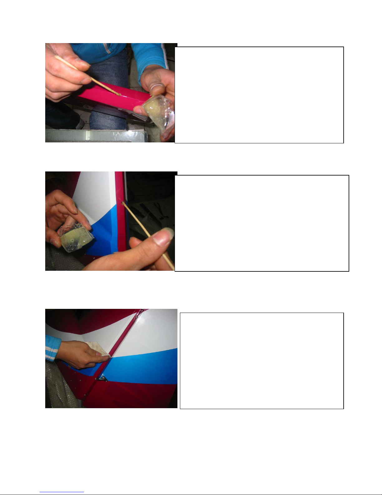
r
finial assembly you may want to add
a
drip of thin CA to the screw holes an
d
re-drill. This will provide a secure
mount.
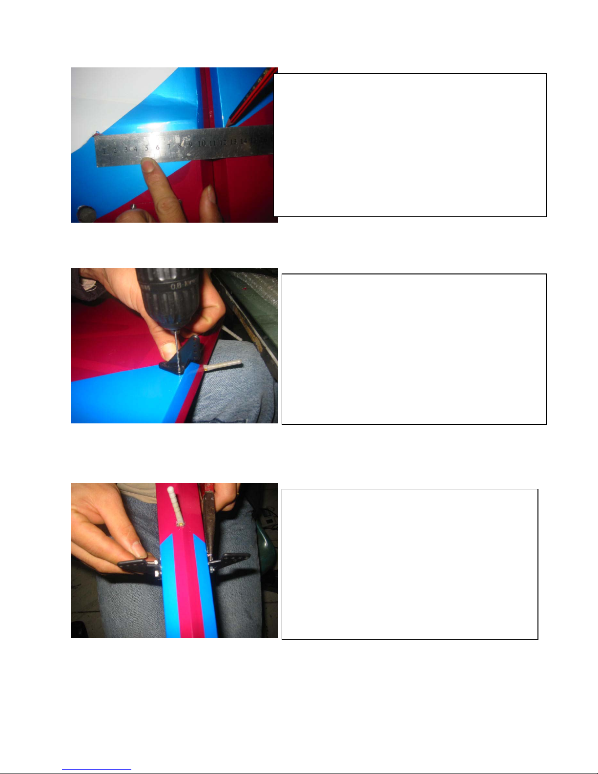
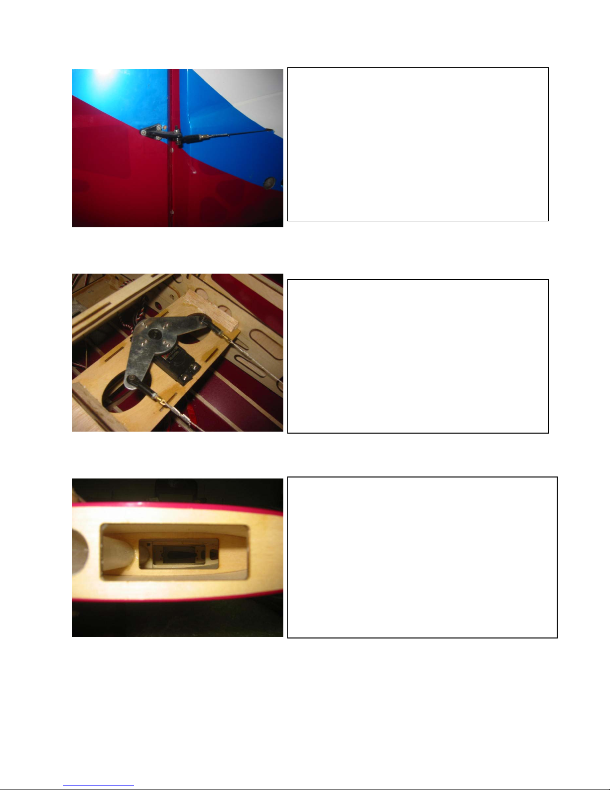
5. Once the servo is installed measure
the length of the push rod.
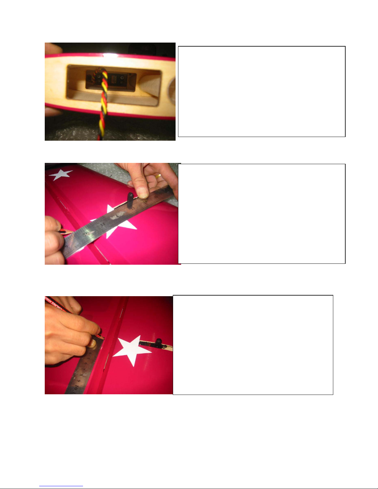
6. Make sure your control horn is place
d
5mm toward the root of the wing. This
measurment is taken from the edge o
f
the servo.
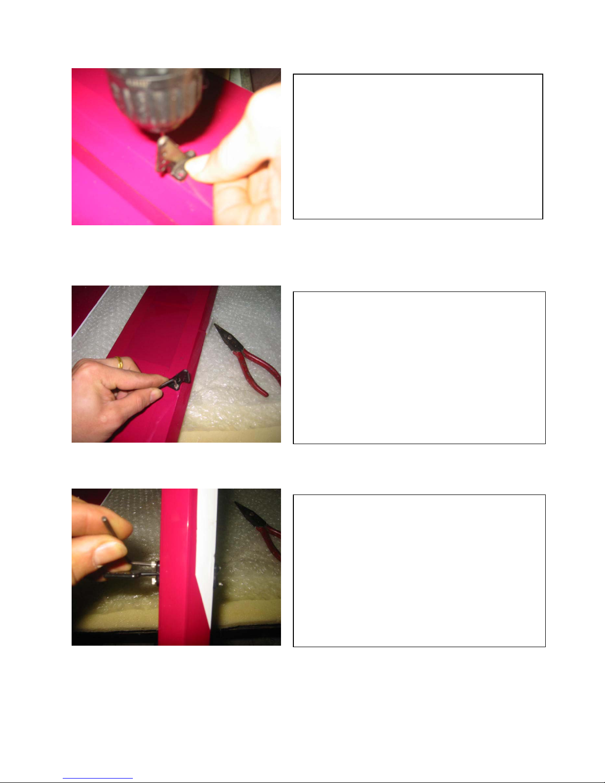
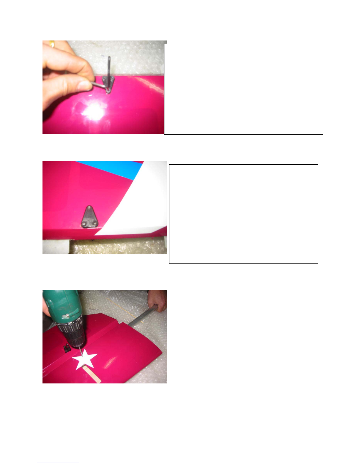
7. Center the aileron and position the control horn as close to
the leading edge as possible. Pre-drill the holes and use the
allen screws provided to mount the control horn. Make
sure to use a drip of thin CA in the hole to provide a stronge
r
mount.
8. Tighten the allen screws, once complete the control hor
n
should look like the picture provided.
9. Make sure that the allen bolt goes through the entire
aileron and into the mounting back plate.
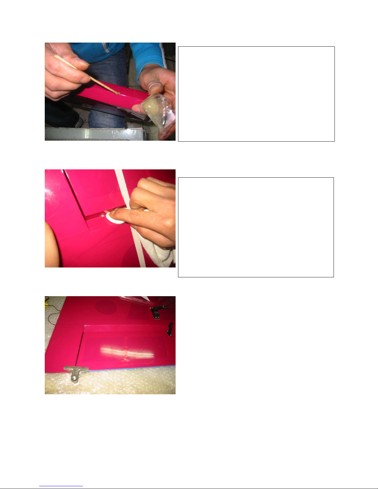
10. Hinge installation
Mix the proper amount of epoxy and coat the hinge
hole.(This is a very important step so make sure you have
p
lenty of epoxy in the hole).
Fig.10
11. Wipe the excess glue away from the hinge and off of the
covering once the surfaces are taped together.
12.Installing pushrods:
Use some type of clamp to help center the
aileron.

13.Measure the length of the pushrod and mark.
Make sure you have plenty of threads left tha
t
will be able to screw into the ball link an
d
control horn (provided).
14. Once you have the proper length, cut the
p
ushrod and install.
15.Place the servo arm back onto the servo an
d
tighten the screw. Make sure the arm is at a
90-degree angle to servo with the control
surface at center.

16.Main Landing Gear Installation:
Use the four 1/4×20 bolts provided to mount the
gear to the gear plate. Back the bolts from the
inside with the four lock nuts. Once the locknuts
are tight you may move to the next step.
17.Tail Wheel Installation:
Install your preferred tail wheel to the hard woo
d
at the rear section of the fuselage. Here is an
example of our installation.
18. Install the blind-nuts needed for the tail wheel
through the acess hatch in the rear portion of the
fuse.
19. Here is a picture of a proper installation o
f
the tail wheel blind-nuts.
20.Here is another example of the tail wheel
installation.
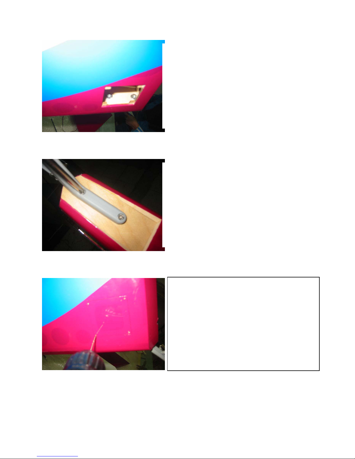
21. Installing the acess hatch.
Use a 1.5mm drill bit to drill the four holes into
the hatch at each corner. Make sure to hit the
mounting block behind the hatch.

22. Use four machine screws 3x6mm to
secure the hatch plate.
23. Using a soldering iron, open the hole in the
rear for the stab tube.
24.Rudder control horn:
Drill through the hard point in the rudde
r
making sure that the control horn will clea
r
the elevators at full up deflection.
25. Rudder Cable
Take a straight edge and mark where the rudder cable will touch the
turtle deck.
You are looking for a straight shot all the way up to your rudde
r
servos.
Make sure you have clearance between the cable and your elevato
r
at full travel.
26.Using the rudder horn provided and place it as marked.
Use a 3mm drill bit to drill through the hard point. Use the
3mm allen bolts to secure the rudder horns together. Back the
allen bolts with lock nuts and move to the next step.
27. Pictures showing the correct position of the rudder horns.
28. Hinge installation
Mix the proper amount of epoxy and coat the hinge hole.(This is
a very important step so make sure you have plenty of epoxy i
n
the hole).
29. Fill the holes with epoxy using a long sharp stick.
30. Make sure all hinge gaps are 1/16 or less. You shoul
d
not be able to see any type of gab in the hinge line if done right.
Once all hinging is done we recommend sealing the gaps wit
h
clear covering. This will prevent any type of flutter problems.
32. Rudder horn installation is completed.
33. Rudder servo installation
The torque of your servos will determine how many servos yo
u
will need to run.
Here is one example of the set up.
34. Stab installation
35. Mount the servo inside of the stab to the stab rib. Use the
fishing line to guide your servo lead out of the root.
36. Locate the servo horn exit hole. Once locate
d
cut open the hole and install your servo horn to
the servo. Locate the center point for your control horn.
Fig.33
37. Move 2mm towards the root rib or fuselage for the cente
r
of the control horn.
38. Use the same method as the aileron to mount your elevato
r
control horns.
39. Make sure all the allen bolts come through the bac
k
p
lane of the control horn. You can cut the bolts flush with
a
cut off wheel.
40.Stab Tube Installation:
The next step is to drill and tap the tail tube.
Insert the tail tube into one side of the stab an
d
then locate the predrilled hole in the stab. Yo
u
will need to drill the tube to accept a 6/32 tap.

41. Now proceed with tapping the tail tube
using a 6/32 tap.
42. Secure the stab tubes using a 6/32 allen bolt.
43. Next step is to slide the stab and stab tube
through the fuselage. Now slide the opposite stab
onto the stab tube and make sure both sides are
p
ressed tight against the fuse. Now follow the
same drill and ta
pp
in
g
ste
p
s as the first stab
Fig.43

44. wheel pant installation:
Install the wheel pant to the landing gear using two
6-32×3/4″allen bolts.
Make sure you have a small 1/16” thick bloc
k
glued to the inside of the pant.
N
ow you can take two of the supplied 6/32 blin
d
nuts and back the bolt.
Once the blind nuts are pulled tight into the wood,
p
lace a small drop of CA or epoxy to the blind nuts
to kee
p
it from fallin
g
out.
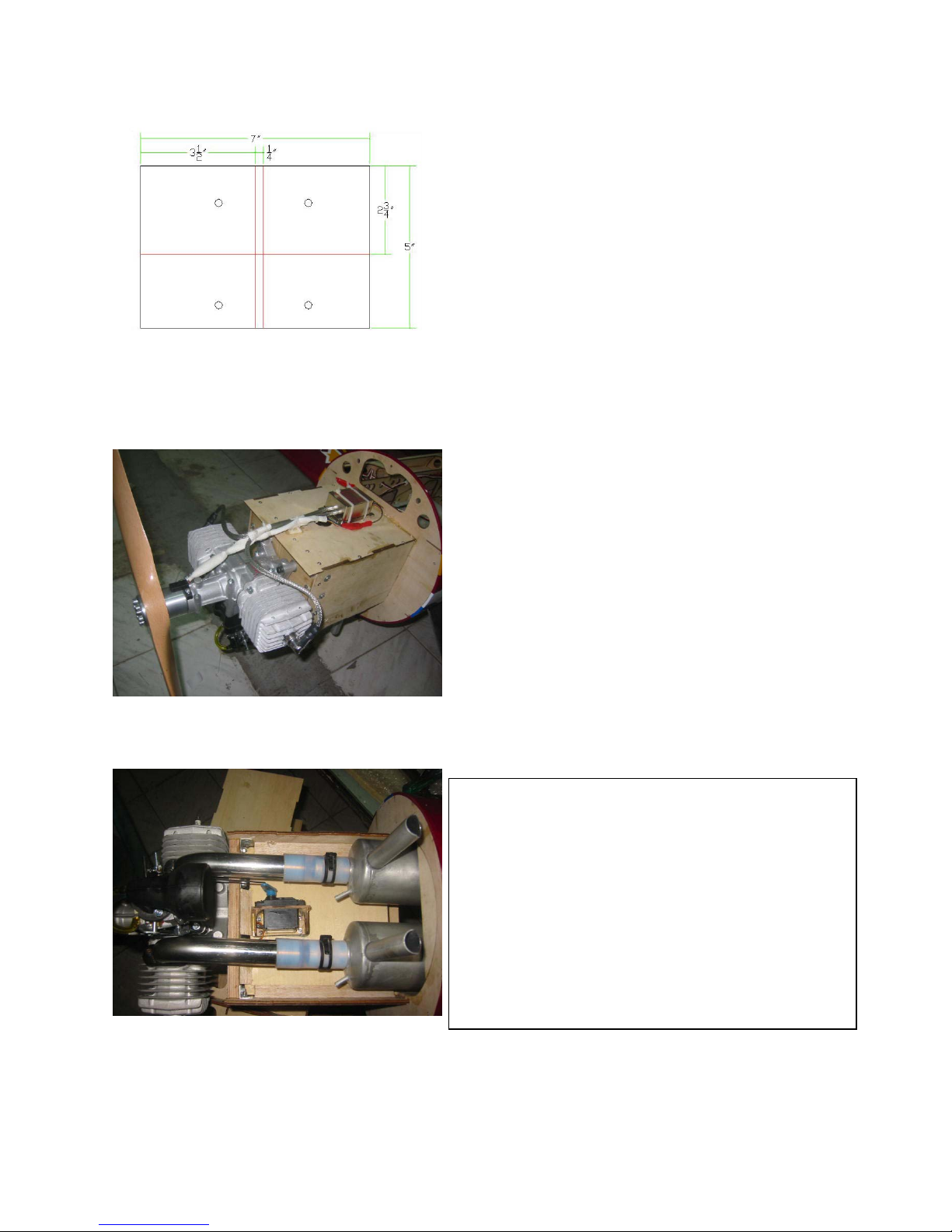
45. Engine installation:
N
ext step is to mark the center of the box. Yo
u
will need to offset then engine to center the
crank. Here is an example of what the firewall
should look like when mounting a 3w106
engine.
46. Here is a picture of a 3W 106 bolted to
the firewall.
47. Canister Installation:
This aircraft is ready to accept canister mufflers. If yo
u
choose to use canisters follow the next few steps.\
Here is a picture of the 3w 106 and PeFa canisters installed.
.
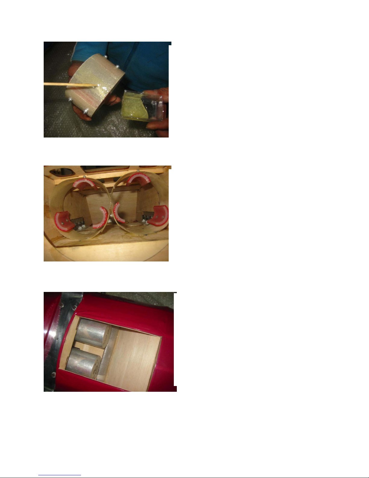
48. Add a small bit of epoxy glue on the
muffler mounting rings. These rings shown
here are 3w Cannister rings.
49. Measure the fixed position of the mufflers
before installing it inside of the fuselage. Once
you have your mounting point finish glueing
the canister mounts to the pipe tunnel.
50. Here is a picture of the canisters installed.

51. Another view of the canister installation.
N
otice the throttle servo mounted below the
engine box.
.
52.Cowling installation:
Using 5 6-32 ×3/4allen head bolts
(provided) attach the cowling to the fuse
using the pre-installed cowl ring.
53. Fuel tank installation.
Mount the fuel tank as close as possible to
the cg of the aircraft. Make sure to
mount the tank on foam to prevent the fuel
from foaming.
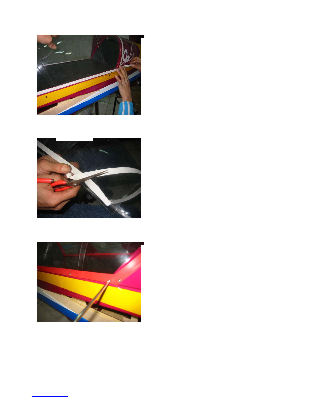
54.Canopy Mounting:
Cut the canopy to fit onto the canopy hatch.
Make sure to take a little off at a time or yo
u
might take to much off.
55. Trim the canopy.
56 .Canopy installations:
Trim the canopy to fit the canopy hatch. Once you
are happy with the fit, glue the canopy to the canopy
hatch with your favorite canopy glue. You may also
install eight small self-tapping screws for adde
d
strength
Table of contents
Popular Toy manuals by other brands


Reely
Reely R222 operating instructions

The World Models Manufacturing
The World Models Manufacturing PIPER J-3 CUB 48S instruction manual

VTech Baby
VTech Baby Sort and Learn Car user manual

Matchbox
Matchbox WOLF MOUNTAIN instructions

Makeblock
Makeblock mBot manual

Athearn
Athearn Genesis SD45-2 user manual