TOCCO TOCCOtron AC User manual

Processes
OM-189 507A
October 2000
TOCCOtron AC
Bench-Top Power Supply
R
Description
InductionHeating
Induction Heating Power Source


TABLE OF CONTENTS
SECTION 1 – SAFETY PRECAUTIONS – READ BEFORE USING 1. . . . . . . . . . . . . . . . . . . . . . . . . . .
1-1. Symbol Usage 1. . . . . . . . . . . . . . . . . . . . . . . . . . . . . . . . . . . . . . . . . . . . . . . . . . . . . . . . . . . . . . . .
1-2. Induction Heating Hazards 1. . . . . . . . . . . . . . . . . . . . . . . . . . . . . . . . . . . . . . . . . . . . . . . . . . . . .
1-3. Additional Symbols for Installation, Operation, and Maintenance 2. . . . . . . . . . . . . . . . . . . . . .
1-4. Principal Safety Standards 2. . . . . . . . . . . . . . . . . . . . . . . . . . . . . . . . . . . . . . . . . . . . . . . . . . . . .
1-5. EMF Information 2. . . . . . . . . . . . . . . . . . . . . . . . . . . . . . . . . . . . . . . . . . . . . . . . . . . . . . . . . . . . . .
SECTION 1 – MESURES DE SECURITE POUR LE CHAUFFAGE PAR INDUCTION 3. . . . . . . . . . . .
1-1. Dangers supplémentaires de mise en route, de fonctionnement et d’entretien 4. . . . . . . . . . .
1-2. Informations concernant les champs électro-magnétiques (Information EMF) 5. . . . . . . . . . .
PRINCIPALES NORMES DE SÉCURITÉ 5. . . . . . . . . . . . . . . . . . . . . . . . . . . . . . . . . . . . . . . . . . . . . .
SECTION 2 – SPECIFICATIONS 6. . . . . . . . . . . . . . . . . . . . . . . . . . . . . . . . . . . . . . . . . . . . . . . . . . . . . . . . .
SECTION 3 – INSTALLATION 6. . . . . . . . . . . . . . . . . . . . . . . . . . . . . . . . . . . . . . . . . . . . . . . . . . . . . . . . . . .
3-1. Connecting Head/Coil To Power Source 6. . . . . . . . . . . . . . . . . . . . . . . . . . . . . . . . . . . . . . . . . .
3-2. Remote 14 Receptacle RC14 Information And Connection 7. . . . . . . . . . . . . . . . . . . . . . . . . . .
3-3. Remote 14 Socket Information 7. . . . . . . . . . . . . . . . . . . . . . . . . . . . . . . . . . . . . . . . . . . . . . . . . .
3-4. Positioning Jumper Links 8. . . . . . . . . . . . . . . . . . . . . . . . . . . . . . . . . . . . . . . . . . . . . . . . . . . . . . .
3-5. Connecting Input Power 9. . . . . . . . . . . . . . . . . . . . . . . . . . . . . . . . . . . . . . . . . . . . . . . . . . . . . . . .
3-6. Electrical Service Guide 9. . . . . . . . . . . . . . . . . . . . . . . . . . . . . . . . . . . . . . . . . . . . . . . . . . . . . . . .
SECTION 4 – OPERATION 10. . . . . . . . . . . . . . . . . . . . . . . . . . . . . . . . . . . . . . . . . . . . . . . . . . . . . . . . . . . . .
4-1. Controls 10. . . . . . . . . . . . . . . . . . . . . . . . . . . . . . . . . . . . . . . . . . . . . . . . . . . . . . . . . . . . . . . . . . . . .
4-2. Safety Equipment 10. . . . . . . . . . . . . . . . . . . . . . . . . . . . . . . . . . . . . . . . . . . . . . . . . . . . . . . . . . . . .
4-3. Power Adjust Control 10. . . . . . . . . . . . . . . . . . . . . . . . . . . . . . . . . . . . . . . . . . . . . . . . . . . . . . . . . .
4-4. Remote Power Control Switch 10. . . . . . . . . . . . . . . . . . . . . . . . . . . . . . . . . . . . . . . . . . . . . . . . . .
4-5. Power Switch 11. . . . . . . . . . . . . . . . . . . . . . . . . . . . . . . . . . . . . . . . . . . . . . . . . . . . . . . . . . . . . . . .
4-6. Duty Cycle Limit LED 11. . . . . . . . . . . . . . . . . . . . . . . . . . . . . . . . . . . . . . . . . . . . . . . . . . . . . . . . . .
4-7. Sequence Of Induction Heating Process 12. . . . . . . . . . . . . . . . . . . . . . . . . . . . . . . . . . . . . . . . . .
SECTION 5 – MAINTENANCE & TROUBLESHOOTING 12. . . . . . . . . . . . . . . . . . . . . . . . . . . . . . . . . . . .
5-1. Routine Maintenance 12. . . . . . . . . . . . . . . . . . . . . . . . . . . . . . . . . . . . . . . . . . . . . . . . . . . . . . . . . .
5-2. Overload Protection 13. . . . . . . . . . . . . . . . . . . . . . . . . . . . . . . . . . . . . . . . . . . . . . . . . . . . . . . . . . .
5-3. Overheating Protection 13. . . . . . . . . . . . . . . . . . . . . . . . . . . . . . . . . . . . . . . . . . . . . . . . . . . . . . . .
5-4. Automatic Shutdown Protection 13. . . . . . . . . . . . . . . . . . . . . . . . . . . . . . . . . . . . . . . . . . . . . . . . .
5-5. Safety Interlock Switch And Measuring Tuning Capacitor Voltage 14. . . . . . . . . . . . . . . . . . . . .
5-6. Measuring Input Capacitor Voltage 14. . . . . . . . . . . . . . . . . . . . . . . . . . . . . . . . . . . . . . . . . . . . . . .
5-7. Troubleshooting 15. . . . . . . . . . . . . . . . . . . . . . . . . . . . . . . . . . . . . . . . . . . . . . . . . . . . . . . . . . . . . .
5-8. Tuning Chart 15. . . . . . . . . . . . . . . . . . . . . . . . . . . . . . . . . . . . . . . . . . . . . . . . . . . . . . . . . . . . . . . . .
SECTION 6 – ELECTRICAL DIAGRAM 18. . . . . . . . . . . . . . . . . . . . . . . . . . . . . . . . . . . . . . . . . . . . . . . . . . .
SECTION 7 – PARTS LIST 20. . . . . . . . . . . . . . . . . . . . . . . . . . . . . . . . . . . . . . . . . . . . . . . . . . . . . . . . . . . . . .
WARRANTY
OM-189 507A


OM-189 507 Page 1
SECTION 1 –SAFETY PRECAUTIONS –READ BEFORE
USING
1-1. Symbol Usage
safety_ihom 5/98
Means Warning! Watch Out! There are possible hazards
with this procedure! The possible hazards are shown in
the adjoining symbols.
YMarks a special safety message.
.Means “Note”; not safety related.
This group of symbols means Warning! Watch Out! possible
ELECTRIC SHOCK, MOVING PARTS, and HOT PARTS hazards.
Consultsymbols and related instructions below for necessary actions
to avoid the hazards.
1-2. Induction Heating Hazards
YThe symbols shown below are used throughout this manual to
call attention to and identify possible hazards. When you see
the symbol, watch out, and follow the related instructions to
avoid the hazard. The safety information given below is only
a summary of the more complete safety information found in
the Safety Standards listed in Section 1-4. Read and follow all
Safety Standards.
YOnly qualified persons should install, operate, maintain, and
repair this unit.
YDuring operation, keep everybody, especially children, away.
ELECTRIC SHOCK can kill.
Touchinglive electrical parts can cause fatal shocks
or severe burns. The power circuit and output bus
bars or connections are electrically live whenever
the output is on. The input power circuit and machine
internal circuits are also live when power is on. Incorrectly installed or
improperlygrounded equipment is a hazard.
DDo not touch live electrical parts.
DEnclose any connecting bus bars and coolant fittings to prevent
unintentionalcontact.
DWear dry, hole-free insulating gloves and body protection.
DInsulateyourself from work and ground using dry insulating mats or
covers big enough to prevent any physical contact with the work or
ground.
DDisconnect input power before installing or servicing this equip-
ment. Lockout/tagout input power according to OSHA 29 CFR
1910.147(see Safety Standards).
DUse only nonconductive coolant hoses with a minimum length of 18
inches (457 mm) to provide isolation.
DProperlyinstall and ground this equipment according to its Owner’s
Manualand national, state, and local codes.
DAlways verify the supply ground –check and be sure that input pow-
er cord ground wire is properly connected to ground terminal in
disconnect box or that cord plug is connected to a properly
groundedreceptacle outlet.
DWhen making input connections, attach proper grounding
conductorfirst –double-check connections.
DFrequentlyinspect input power cord for damage or bare wiring –re-
place cord immediately if damaged –bare wiring can kill.
DTurn off all equipment when not in use.
DDo not use worn, damaged, undersized, or poorly spliced cables.
DDo not drape cables over your body.
DDo not touch power circuit if you are in contact with the work,
ground,or another power circuit from a different machine.
DUse only well-maintained equipment. Repair or replace damaged
parts at once. Maintain unit according to manual.
DWear a safety harness if working above floor level.
DKeep all panels and covers securely in place.
SIGNIFICANT DC VOLTAGE exists after removal of
input power on inverters.
DTurn Off inverter, disconnect input power, and discharge input
capacitorsaccording to instructions in Maintenance Section before
touchingany internal parts.
INDUCTION HEATING can cause burns.
DHot parts and equipment can injure.
DDo not touch or handle induction head/coil
duringoperation.
DDo not touch hot parts bare-handed.
DAllow cooling period before handling parts or equipment.
DKeep metal jewelry and other metal personal items away from
head/coilduring operation.
FIRE OR EXPLOSION hazard.
DDo not overheat parts and adhesive.
DWatch for fire; keep extinguisher nearby.
DKeep flammables away from work area.
DDo not locate unit on, over, or near combustible surfaces.
DDo not install unit near flammables.
DDo not operate unit in explosive atmosphere.
Induction Heating of certain materials, adhesives,
and fluxes can produce fumes and gases. Breathing
these fumes and gases can be hazardous to your
health.
FUMES AND GASES can be hazardous.
DKeep your head out of the fumes. Do not breathe the fumes.
DIf inside, ventilate the area and/or use exhaust to remove fumes
and gases.
DIf ventilation is poor, use an approved air-supplied respirator.
DRead the Material Safety Data Sheets (MSDSs) and the
manufacturer’s instruction for adhesives, fluxes, metals,
consumables,coatings, cleaners, and degreasers.
DWork in a confined space only if it is well ventilated, or while wearing
an air-supplied respirator. Always have a trained watchperson
nearby. Fumes and gases from heating can displace air and lower
the oxygen level causing injury or death. Be sure the breathing air is
safe.
DDo not heat in locations near degreasing, cleaning, or spraying op-
erations.The heat can react with vapors to form highly toxic and
irritatinggases.
DDo not overheat coated metals, such as galvanized, lead, or
cadmium plated steel, unless the coating is removed from the
heated area, the area is well ventilated, and if necessary, while
wearing an air-supplied respirator. The coatings and any metals
containingthese elements can give off toxic fumes if overheated.
See coating MSDS for temperature information.
OM-189 507 Page 2
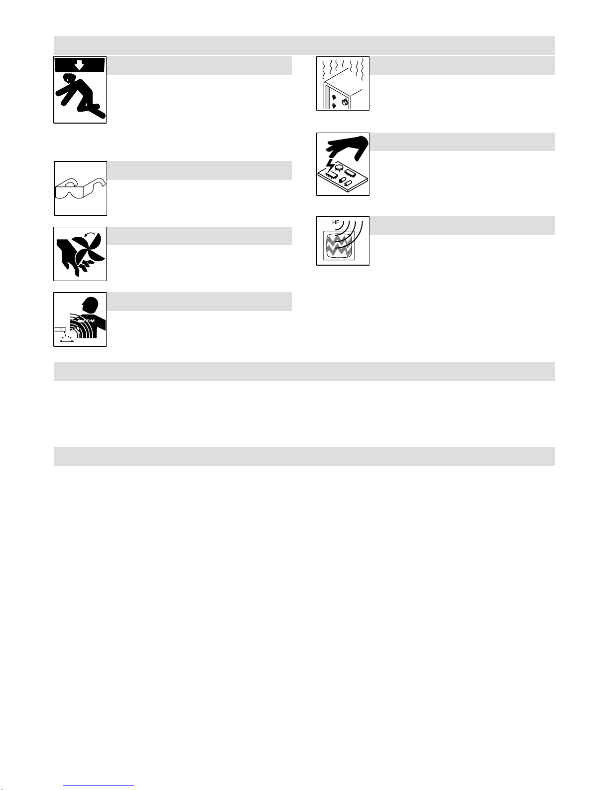
1-3. Additional Symbols for Installation, Operation, and Maintenance
FALLING UNIT can cause injury.
DUse handle and have person of adequate
physical strength lift unit.
DMove unit with hand cart or similar device.
DFor units without a handle, use equipment of
adequatecapacity to lift unit.
DWhenusing lift forks to move unit, be sure forks are long enough
to extend beyond opposite side of unit.
FLYING METAL OR ADHESIVE can injure eyes.
DWear approved safety glasses with side
shields or wear face shield.
MOVING PARTS can cause injury.
DKeep away from moving parts such as fans.
DKeep all doors, panels, covers, and guards
closed and securely in place.
MAGNETIC FIELDS can affect pacemakers.
DPacemaker wearers keep away.
DWearers should consult their doctor before
goingnear induction heating operations.
OVERUSE can cause OVERHEATING
DAllow cooling period.
DReduce output or reduce duty cycle before
startingto heat again.
DFollow rated duty cycle.
STATIC (ESD) can damage PC boards.
DPut on grounded wrist strap BEFORE handling
boards or parts.
DUse proper static-proof bags and boxes to
store, move, or ship PC boards.
H.F. RADIATION can cause interference.
DHigh-frequency(H.F.) can interfere with radio
navigation, safety services, computers, and
communicationsequipment.
DHave only qualified person familiar with electronic equipment per-
form this installation.
DThe user is responsible for having a qualified electrician promptly
correct any interference problem resulting from the installation.
DIf notified by the FCC about interference, stop using the equip-
ment at once.
DHave the installation regularly checked and maintained.
DKeep high-frequency source doors and panels tightly shut.
1-4. Principal Safety Standards
Safety and Health Standards, OSHA 29 CFR 1910, from Superinten-
dent of Documents, U.S. Government Printing Office, Washington, D.C.
20402.
National Electrical Code, NFPA Standard 70, from National Fire Protec-
tion Association, Batterymarch Park, Quincy, MA 02269.
CanadianElectrical Code Part 1, CSA Standard C22.1, from Canadian
Standards Association, Standards Sales, 178 Rexdale Boulevard,Rex-
dale,Ontario, Canada M9W 1R3.
Safe Practices For Occupation And Educational Eye And Face Protec-
tion, ANSI Standard Z87.1, from American National Standards Institute,
1430 Broadway, New York, NY 10018.
1-5. EMF Information
ConsiderationsAbout Induction Heating And The Effects Of Low Fre-
quency Electric And Magnetic Fields
The following is a quotation from the General Conclusions Section of the
U.S. Congress, Office ofTechnology Assessment, Biological Effects of
Power Frequency Electric & Magnetic Fields –Background Paper,
OTA-BP-E-53(Washington, DC: U.S. Government Printing Office,May
1989):“. . . there is now a very large volume of scientific findings based
on experiments at the cellular level and from studies with animals and
peoplewhich clearly establish that low frequency magnetic fields can
interactwith, and produce changes in, biological systems. While most of
this work is of very high quality, the results are complex. Current scientif-
ic understanding does not yet allow us to interpret the evidence in a
singlecoherent framework. Even more frustrating, it does not yet allow
us to draw definite conclusions about questions of possible risk or to of-
fer clear science-based advice on strategies to minimize or avoid
potentialrisks.”
To reduce magnetic fields in the workplace, use the following proce-
dures:
1. Arrangeoutput cable to one side and away from the operator.
2. Do not coil or drape output cable around the body.
3. Keep power source and cable as far away from the operator as
practical.
About Pacemakers:
The above procedures are also recommended for pacemaker wearers.
Consultyour doctor for complete information.
OM-189 507 Page 3
SECTION 1 –MESURES DE SECURITE POUR LE
CHAUFFAGE PAR INDUCTION safetyihom_fre 5/98
PRENDRE LES MESURES NECESSAIRES POUR EVITER LES RISQUES DE BLESSURES GRAVES, VOIRE
MORTELLES. TENIR LES ENFANTS A DISTANCE. LES PORTEURS D’UN STIMULATEUR CARDIAQUE DOIVENT
PREALABLEMENT CONSULTER LEUR MEDECIN.
Pendant les opérations de chauffage, comme dans la plupart des activités, l’opérateur s’expose àcertains dangers.
Le chauffage n’est pas dangereux àcondition de prendre certaines mesures. Les consignes de sécuritéindiquées
ci-après ne sont qu’un résumédes informations plus détaillées se trouvant dans les normes de sécuritéénumérées
àla page suivante. Lire et respecter toutes les normes de sécurité.
LES OPERATIONS D’INSTALLATION, DE FONCTIONNEMENT, DE MAINTENANCE ET DE REPARATION NE DOIVENT
ETRE CONFIEES QU’A DU PERSONNEL QUALIFIE.
LE CHAUFFAGE PAR INDUCTION peut être dangereux.
AVERTISSEMENT
Danger de mort PAR ELECTROCUTION.
Le contact de composants électriques peut
provoquer des accidents mortels ou des brûlures
graves. Le circuit de puissance et les connexions de
sortie sont sous tension lorsqu’on active la sortie. Le
circuit d’alimentation et les circuits internes de la
machine sont également sous tension lorsque
l’alimentation est sur marche. Des équipements
installés ou reliés àla borne de terre de manière
incorrectesont dangereux.
1. Ne pas toucher des composants électriques sous tension.
2. Envelopper les connexions et raccords de refroidissement pour
éviter tout contact accidentel.
3. Porter des gants d’isolation secs, sans trous, et une protection
corporelle.
4. Isolez-vous de la pièce et du sol avec des tapis ou des
couvertures d’isolation suffisamment grands pour prévenir tout
contact physique avec la pièce ou la terre.
5. Déconnecter l’alimentation avant d’installer l’appareil ou d’en
effectuer l’entretien. Verrouiller ou étiqueter la sortie
d’alimentation selon la norme OSHA 29 CFR 1910.147
(se reporter aux Principales normes de sécurité).
6. Utiliser seulement des tuyaux non conducteurs avec une
longueurminimale de 460 mm pour assurer l’isolement.
7. Installer et mettre cet équipement correctement àla terre
conformément au manuel utilisateur et aux codes nationaux,
gouvernementauxet locaux.
8. Vérifiersouvent la terre de l’alimentation –contrôler et s’assurer
que le conducteur de terre du câble d’alimentation est
correctement reliéàla borne de terre dans le boîtier de
déconnexionou que le connecteur est branchéàune sortie de
boîtiercorrectement mise àla terre.
9. En réalisant des connexions d’entrée brancher d’abord le
conducteur de terre approprié–contrôler deux fois les
connexions.
10. Vérifiersouvent le bon état du câble d’alimentation ou l’isolation
des fils –remplacer le câble immédiatement s’il est endommagé–
des fils dénudés peuvent provoquer des accidents mortels.
11. Arrêter tous les équipements lorsqu’ils ne sont pas utilisés.
12. Ne pas utiliser des câbles usés, endommagés, sous
dimensionnésou mal épissés.
13. Ne pas porter les câbles autour de votre corps.
14. Ne pas toucher le circuit électrique si vous êtes en contact avec la
pièce, la terre ou le circuit électrique d’une autre machine.
15. Utiliserseulement des équipements bien entretenus. Réparer ou
remplacer immédiatement des composants endommagés.
Effectuer des travaux d’entretien sur l’appareil selon le manuel.
16. Porter un harnais de sécuritépour effectuer des travaux
au-dessus du sol.
17. Maintenir solidement en place tous les panneaux et couvercles.
LE CHAUFFAGE PAR INDUCTION peut
provoquer des blessures ou des
brûlures au contact de PIECES
CHAUDES OU DE L’EQUIPEMENT.
1. Ne pas toucher ou manipuler la tête/l’enroulement àinduction
pendantle fonctionnement.
2. Tenirles bijoux et autres objets personnels en métal éloignés de
la tête/de l’enroulement pendant le fonctionnement.
3. Laisser refroidir les composants ou équipements avant de les
manipuler.
LE CHAUFFAGE PAR INDUCTION peut
provoquer un incendie.
1. Ne pas surchauffer les composants ni les
adhésifs.
2. Attention aux risques d’incendie: tenir un
extincteuràproximité.
3. Stocker des produits inflammables hors de la
zone de travail.
La mise en place de l’appareil sur, au-dessus ou à
proximitéde surfaces inflammables peut être source
d’INCENDIES OU d’EXPLOSION.
1. Ne pas placer l’appareil sur, au-dessus ou àproximitéde
surfaces infllammables.
2. Ne pas installer l’appareil àproximitéde produits inflammables
3. Ne pas faire fonctionner l’appareil en atmosphère explosive.

OM-189 507 Page 4
DES FUMEES ET DES GAZ peuvent
être dangereux pour votre santé.
Le chauffage àinduction génère des fumées et des
gaz. Leur inhalation peut être dangereuse pour votre
santé.
1. Eloigner la tête des fumées. Ne pas respirer les fumées.
2. A l’interieur, ventiler la zone et/ou utiliser un extracteur pour
l’évacuationdes fumées et des gaz.
3. Si la ventilation est insuffisante, utiliser un respirateur à
alimentationd’air homologué.
4. Lire les spécifications de sécuritédes matériaux (MSDSs) et les
instructions du fabricant concernant les adhésifs, les métaux, les
consommables, les revêtements, les nettoyants et les
dégraisseurs.
5. Travaillerdans un espace ferméseulement s’il est bien ventiléou
en portant un respirateur. Demander toujours àun surveillant
dûment forméde se tenir àproximité. Des fumées et des gaz
provenantdu chauffage peuvent déplacer l’air, abaisser le niveau
d’oxygène, et provoquer des lésions ou des accidents mortels.
S’assurer que l’air ambiant ne présente aucun danger.
6. Ne pas chauffer dans des endroits se trouvant àproximité
d’opérationsde dégraissage, de nettoyage ou de pulvérisation. La
chaleur peut réagir en présence de vapeurs et former des gaz
hautementtoxiques et irritants.
7. Ne pas chauffer des métaux munis d’un revêtement tels que l’acier
galvanisé, plaquéau plomb ou au cadmium, àmoins que le
revêtementne soit enlevéde la zone chauffée, que la zone soit
bien ventilée et, si nécessaire, en portant un respirateur. Les
revêtementset tous les métaux contenant ces éléments peuvent
dégager des fumées toxiques s’ils sont chauffés.
1-1. Dangers supplémentaires de mise en route, de fonctionnement et d’entretien
LA CHUTE DE MATERIEL peut provoquer
des blessures personnelles graves et en-
dommager les équipements.
1. Utiliser la poignée et demander àune personne
ayant la force physique nécessaire pour soulever
l’appareil.
2. Déplacer l’appareil àl’aide d’un charriot ou d’un
enginsimilaire.
3. Pour les appareils sans poignée utiliser un équipe-
ment d’une capacitéappropriée pour soulever
l’appareil.
4. En utilisant des fourches de levage pour déplacer
l’unité, s’assurer que les fourches sont suffisamment
longues pour dépasser du côtéopposéde l’appareil.
LA PROJECTION DE PIECES DE METAL ou
DE COLLE peut provoquer des blessures
aux yeux.
1. Porter des lunettes de protection avec des protec-
tions latérales.
DES ORGANES MOBILES peuvent
provoquer des blessures.
1. S’abstenirde toucher des organes mobiles tels que
des ventilateurs.
2. Maintenir fermés et fixement en place les portes, pan-
neaux, recouvrements et dispositifs de protection.
DES CHAMPS MAGNETIQUES CREES PAR
DES COURANTS ELEVES peuvent affecter le
fonctionnement du stimulateur cardiaque.
1. Porteurs de stimulateur cardiaque, restez àdistance.
2. Les porteurs d’un stimulateur cardiaque doivent d’a-
bord consulter leur médecin avant de s’approcher
des opérations de chauffage àinduction.
UNE UTILISATION INTENSIVE peut provo-
quer un SURCHAUFFEMENT DU MATERIEL.
1. Prévoir une période de refroidissement
2. Réduirele courant de sortie ou le facteur de marche
avant de recommencer le chauffage.
3. Respecter le facteur de marche nominal.
L’ELECTRICITE STATIQUE peut endomma-
ger les composants des tableaux électri-
ques.
1. Etablir la connexion avec la barrette de terre avant
de manipuler des cartes ou des pièces.
2. Utiliser des pochettes et des boîtes antistatiques
pour stocker, déplacer ou expédier des cartes PC.
Il subsiste DU COURANT CONTINU IMPOR-
TANT après la mise hors tension de l’alimen-
tation électrique.
1. Avant de toucher des organes internes, arrêter la
source électrique, débrancher l’alimentation, et dé-
chargerles condensateurs d’alimentation conformé-
mentaux instructions indiquées dans la partie main-
tenance.
LE RAYONNEMENT HAUTE FREQUENCE
peut provoquer des interférences avec les
équipements de radio-navigation et de com-
munication, les services de sécuritéet les or-
dinateurs.
•Demander seulement àdes personnes qualifiées
familiarisées avec des équipements électroniques
de faire fonctionner l’installation.
•L’utilisateurest tenu de faire corriger rapidement par
un électricien qualifiéles interférences résultant de
l’installation.
•Si le FCC signale des interférences, arrêter immé-
diatement l’appareil.
•Effectuer régulièrement le contrôle et l’entretien de
l’installation.
•Maintenirsoigneusement fermés les portes et les
panneauxdes sources de haute fréquence.

OM-189 507 Page 5
1-2. Informations concernant les champs électro-magnétiques (Information EMF)
Considérationsrelatives au chauffage àinduction et aux effets des
champs électriques et magnétiques basse fréquence.
Le texte suivant est extrait des conclusions générales Département
du Congrès U.S., Office of Technology Assessment, Effets
biologiques des champs magnétiques et électriques basse
fréquence –Background Paper, OTA-BP-E-53 (Washington, DC:
U.S. Government Printing Office, May 1989): “. . . on dispose
maintenant d’importantes découvertes scientifiques reposant sur
des expériences effectuées dans le domaine cellulaire et des études
réalisées sur des animaux et des personnes qui démontrent
clairementque des champs magnétiques basse fréquence peuvent
avoir une interaction et produire des changements dans les
systèmes biologiques. Alors que la plus grande partie de cet ouvrage
est d’une très grande qualité, les résultats sont complexes. La
compréhensionscientifique courante ne nous permet pas encore
d’interpréterla preuve fournie dans un seul ouvrage cohérent. Il est
encore plus frustrant de ne pas pouvoir tirer des conclusions
définitivesen ce qui concerne les problèmes de risque possible ou de
proposer des recommandations scientifiques claires pour des
stratégiesàsuivre en vue de minimiser ou de prévenir des risques
potentiels.”
Pour réduire les champs magnétiques sur le poste de travail,
appliquerles procédures suivantes :
4. Disposer le câble de sortie d’un côtéàdistance de l’opérateur
5. Ne pas enrouler ou draper le câble électrique autour du corps.
6. Placer la source de courant et le câble le plus loin possible de
l’opérateur.
En ce qui concerne les stimulateurs cardiaques
Les procédures ci-dessus concernent également les porteurs de
stimulateurcardiaque. Consulter votre médecin pour un complément
d’information.
PRINCIPALES NORMES DE SÉCURITÉ
Normes de sécuritéet de santé, OSHA 29 CFR 1910, from
Superintendent of Documents, U.S. Government Printing Office,
Washington,D.C. 20402.
Code électrique national, NFPA Standard 70, from National Fire
ProtectionAssociation, Batterymarch Park, Quincy, MA 02269.
Code électrique du Canada, partie 1, CSA Standard C22.1, from
Canadian Standards Association, Standards Sales, 178 Rexdale
Boulevard,Rexdale,Ontario, Canada M9W 1R3.
Safe Practices For Occupation And Educational Eye And Face
Protection, ANSI Standard Z87.1, from American National Standards
Institute,1430 Broadway, New York, NY 10018.
OM-189 507 Page 6
SECTION 2 –SPECIFICATIONS
Type of
Input Power Output
Frequency Rated
Output
Required
Reflective
Inductance
Input
Amperes At
Rated Output
KVA/KW
Used At
Rated Output
Overall
Dimensions Weight
Three-Phase,
230 Or 460
Volts AC,
50/60 Hz 10 To 50 kHz
10 kW At 30%
Duty Cycle;
Max 200 A
(RMS), 350 V
(RMS)
5 to 30 µh
44 A At 230 V
*0.6 A:
22 A At 460 V
*0.3 A
17 kVA/12.6 kW
*0.15 kVA/0.146
kW
Length: 19-1/2
in (495 mm)
Width: 11-1/2 in
(292 mm)
Height: 11-3/4 in
(298 mm)
Net: 65 lb
(29.5 kg)
Ship: 70 lb
(31.8 kg)
*While idling
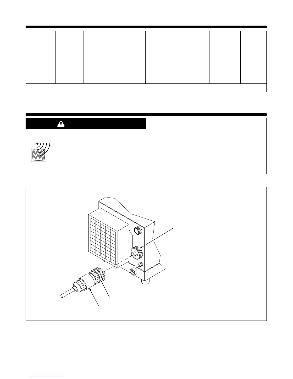
SECTION 3 –INSTALLATION
WARNING
HIGH-FREQUENCY RADIATION can interfere with radio navigation, safety services,
computers, and communications equipment.
•Have only qualified person familiar with electronic equipment perform this installation.
•The user is responsible for having a qualified electrician promptly correct any interference problem resulting from the installation.
•If notified by the FCC about interference, stop using the equipment at once.
•Have the installation regularly checked and maintained.
•Keep high-frequency source doors and panels tightly shut.
3-1. Connecting Head/Coil To Power Source
802 663
1 Output Receptacle RC15
2 Plug From Head/Coil
3 Threaded Collar
Receptacle RC15 is a 4-socket
receptacle.
To connect to receptacle, align key-
way, insert plug, and tighten
threadedcollar.
Rear Panel
Socket Information:
A, C Approx.350 volts ac, 10 to 50 kHzRMS high-
frequencyoutput
B, D Approx.350 volts ac, 10 to 50 kHzRMS high-
frequencyoutput
2
3
1

OM-189 507 Page 7
3-2. Remote 14 Receptacle RC14 Information And Connection
sb7.1* 3/93 - Ref. S-0004-A / Ref. S-0750 / Ref. 802 663
1 Plug
2 ThreadedCollar
3 Keyway
4 Remote 14 Receptacle RC14
(See Section 3-3)
To connect to receptacle, align key-
way, insert plug, and tighten
threadedcollar.
12
4
AJ
BKI
CLNH
DMG
EF
3
4
3-3. Remote 14 Socket Information
Socket Socket Information
A+24 volts dc.
Contactor A
B+24 volts dc.
Contact closure to A completes 24 volts dc contactor control circuit.
CCommand reference; +10 volts dc.
Remote C
DCommand reference; +10 volts dc.
Control circuit common.
AJ
BKIOutput
Control
D
EControl circuit common.
Input command signal (potentiometer wiper or 0 to +10 volts dc).
B
I
LNH
Control E
GInput command signal (potentiometer wiper or 0 to +10 volts dc).
Not used.
4
CLNH
DMG
EFPower
Source
Fault
F,J Absence of internal contact closure between F and J signals power source failu-
re to remote control device.
HCoil loss compensation value.H
ICoil loss compensation value.
Actual frequency output signal (1 volt/5 kHz).
Remote
I
LActual frequency output signal (1 volt/5 kHz).
Average power output signal (1 volt/1 kW).
Remote
Metering L
MAverage power output signal (1 volt/1 kW).
Voltage output signal RMS (1 volt/50 volts).
NCurrent output signal RMS (1 volt/50 amperes).
KChassis common.
OM-189 507 Page 8
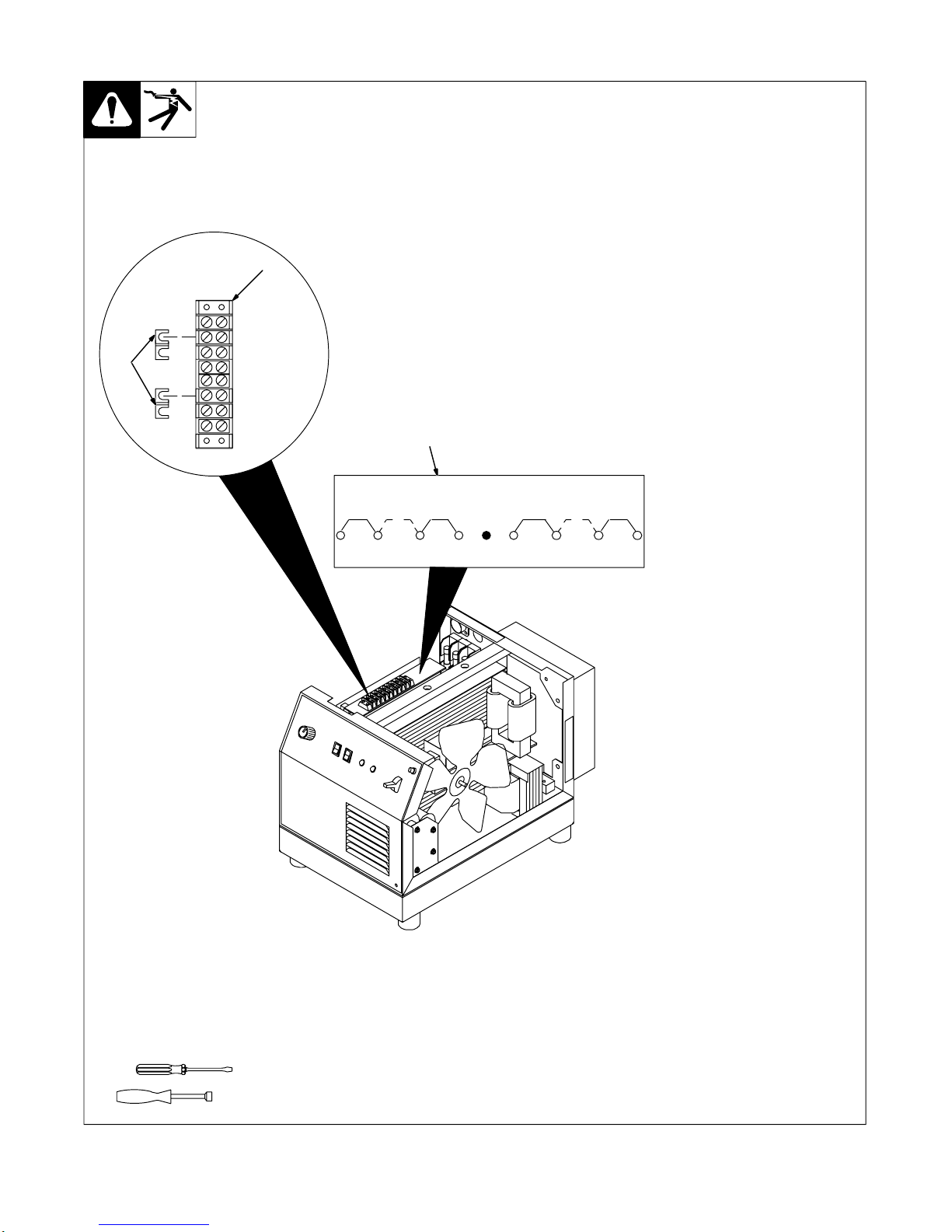
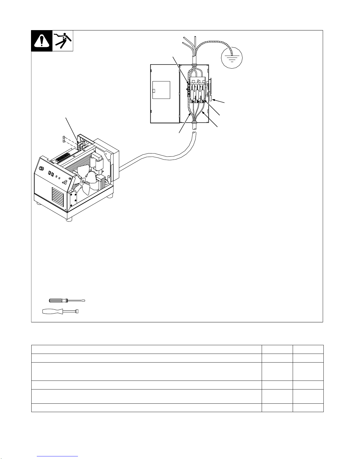
3-4. Positioning Jumper Links
Ref. 802 664
Turn Off unit Power switch, and dis-
connect input power.
Jumperlinks allow operation on dif-
ferentinput voltages and are facto-
ry set for the highest input voltage.
Check input voltage available at
site.
Remove wrapper to check jumper
links.
1 TerminalStrip TE2
2 Input Voltage Jumper Link
3 Input Voltage Label
Four jumper links supplied. Look at
jumper links and compare link
positionwith label.
Move links to match input voltage.
For example, use 230 volts position
on label when 230 volts input power
is available.
Reinstall wrapper or go on to
Section3-5.
Tools Needed:
5/16 in
230 460
S-170 603-A
230 460 230230
1
2
3
OM-189 507 Page 9
3-5. Connecting Input Power
802 664
Have only qualified persons make
this installation.
Remove wrapper.
1 Line Disconnect Device Of
Proper Rating
Obtain and install line disconnect
device.
2 InputConductors
3 Grounding Conductor
Select size and length using
Section3-6. Conductor rating must
comply with national, state, and
local electrical codes.
4 Disconnect Device Ground
Terminal
Install and connect grounding
conductor and input conductors in
conduit or equivalent to
deenergized line disconnect
device.
Connect grounding conductor first,
then line input conductors.
Be sure grounding conductor goes
to an earth ground.
Reinstall wrapper.
5 Overcurrent Protection
Select type and size using Section
3-6. Install into deenergized line
disconnect device (fused
disconnectswitch shown).
6 Unit Fuse Block
Internal replacement fuses:
230 V –KTKR30*
460 V –FWC25A10F
Tools Needed:
5/16 in
1
5
3
4
2
6
*Due to low duty cycle, fusing requirements
can be derated for 230 V operation.
3-6. Electrical Service Guide
Input Voltage 230 460
Input Amperes At Rated Output 44 22
Max Recommended Standard Fuse Rating In Amperes 1
Normal Operating 260 30
Min Input Conductor Size In AWG/Kcmil 10 14
Max Recommended Input Conductor Length In Feet (Meters) 100
(31) 159
(49)
Min Grounding Conductor Size In AWG/Kcmil 10 14
Reference: 1999 National Electrical Code (NEC)
1 Consult factory for circuit breaker applications.
2“NormalOperating”(general purpose –no intentional delay) fuses are UL class “K5”(up to and including 60 amp), and UL class “H”( 65 amp and
above).
OM-189 507 Page 10
SECTION 4 –OPERATION
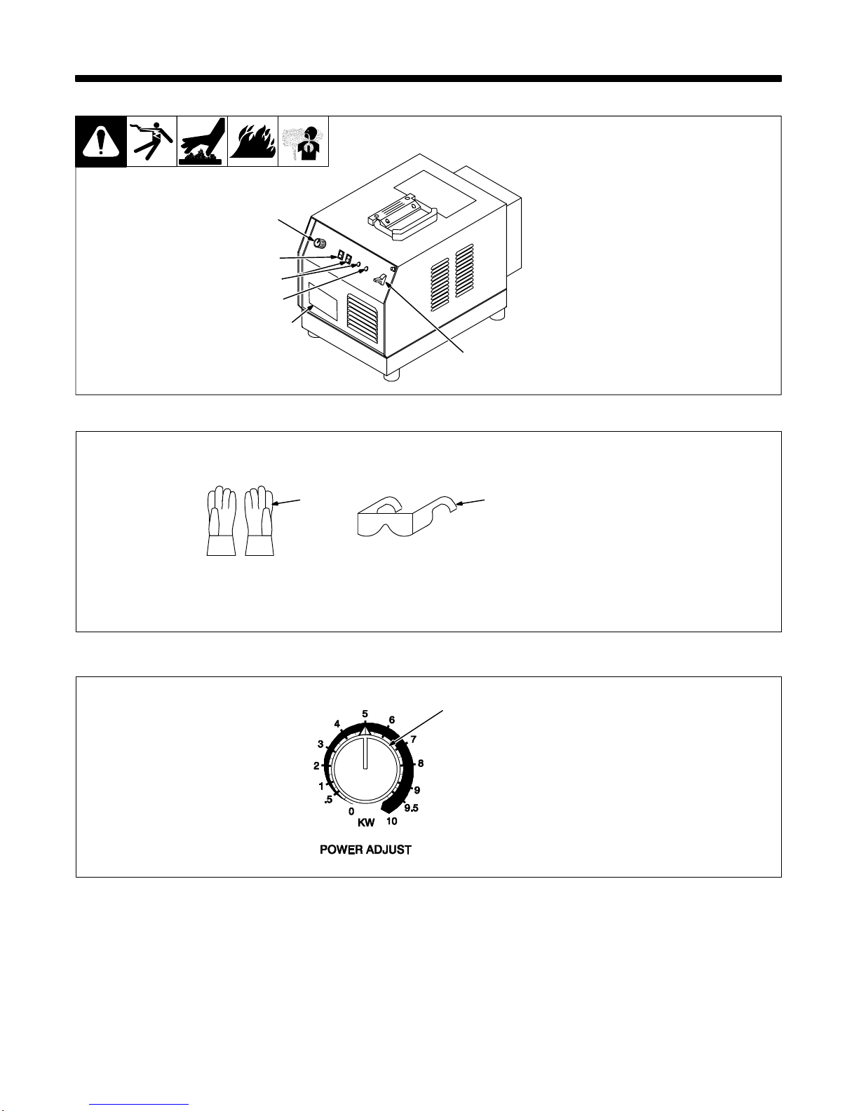
4-1. Controls
Ref. 802 662
1 Power Adjust Control
2 Remote Power Control Switch
3 Ground Fault Test Switch And
Ground Fault LED
4 Duty Cycle Limit LED
5 Power Switch
6 Rating Label Location
1
2
3
5
6
4
4-2. Safety Equipment
sb3.1* 10/91
1 InsulatingGloves
2 Safety Glasses With Side
Shields
Wear dry insulating gloves and
safety glasses with side shields.
1 2
4-3. Power Adjust Control
Ref. 189 500
1 Power Adjust Control
Use control to select power
between the minimum and
maximum output of the power
source. The numbers around the
control are in kilowatts (kW).
1
OM-189 507 Page 11
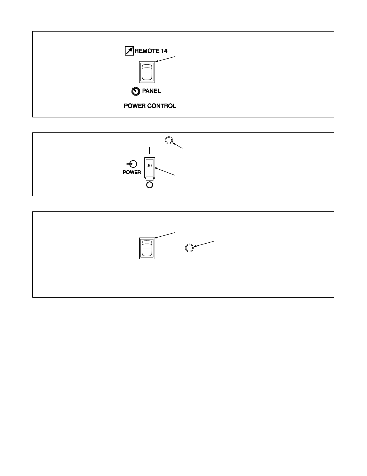
4-4. Remote Power Control Switch
1 RemotePower Control Switch
Use switch to select way of
controllingunit output.
For front panel control, place switch
in Panel position.
For remote control, place switch in
Remote 14 position. Connect
controller or pendant control to
Remote14 receptacle (see Section
3-2).
1
4-5. Power Switch
2
1 Power Switch
2 Pilot Light
Use switch to turn unit, fan motor,
and pilot light On and Off.
Unit is ready to heat 10 seconds
afterPower switch is placed in On
position.
1
4-6. Ground Fault Test Switch And Indicator Light
1 GroundFault Test Switch
Use switch to test ground fault
circuitry.
2 Ground Fault Indicator Light
Light comes on when circuitry
detects a ground fault.
1
GROUND FAULT
FAULT
PRESS
TO TEST
2
OM-189 507 Page 12
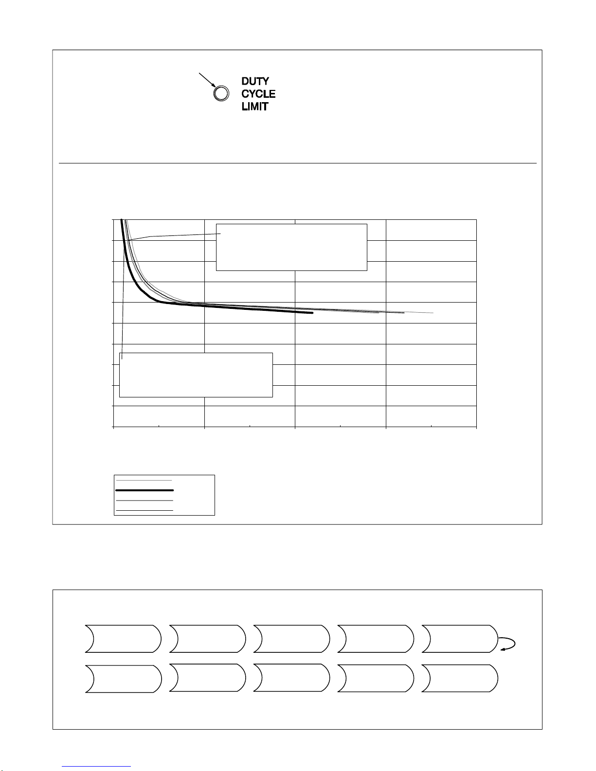
4-7. Duty Cycle Limit LED
1 Duty Cycle Limit LED
Indicates unit has exceeded 30%
duty cycle at 10 kW output.
To restore output, turn off unit
power for a minimum of 1 minute
before energizing unit again (see
Section4-5).
1
10 kW Power Source duty cycle limit curves
0.0
1.0
2.0
3.0
4.0
5.0
6.0
7.0
8.0
9.0
10.0
0 100 200 300 400
Max On–Time in Seconds
Output Power in KW
trip time
10 sec
20 sec
30 sec
MINIMUM
OFF–TIME This chart shows a comparison of output power level vs output on time with re-
spect to off time or time between cycles of the 10kW power source.
Example #1
Power source can be operated at 9kw
for approximately 11 sec without
tripping providing that the time between
Example #2
Power source can be operated at 9kw
for approximately 16 sec without
tripping providing that the time between
cycles is no less than 30 seconds.
cycles is no less than 10 seconds.
4-8. Sequence Of Induction Heating Process
Install & Connect
Power Source Put On
Personal Safety
Equipment
Set
Controls Turn On
Power
Switch
Wait
10 Seconds Unit Ready
To Heat
Turn On
Coolant Supply,
Position Work
Near
Head/Coil
Install & Connect
Induction Install & Connect
Coolant Supply,
If Required If RequiredHead/Coil
OM-189 507 Page 13
SECTION 5 –MAINTENANCE & TROUBLESHOOTING
5-1. Routine Maintenance
YDisconnectpower
before maintaining. .Maintain more often
during severe conditions.
3 Months
RepairOr Replace
Cracked Output
Cables
Clean And
Tighten Output
Connections
6 Months
Replace
DamagedOr
Unreadable
Labels
Blow Out Or
Vacuum Inside
OM-189 507 Page 14
5-2. Overload Protection
Ref. 802 664 / Ref. 802 663
YTurn Off and disconnect
input power before checking
fuses.
1 Unit Fuse Block And Fuses
F1, F2, And F3 (See Section
3-6 For Rating)
Fuses F1, F2, and F3 protect unit
from overload. If fuse(s) opens, the
power source shuts down.
Replace fuses as needed. Use
propertool when removing fuses.
Reinstall wrapper.
2 Fuse F4 (See Parts List For
Rating)
Fuse F4 protects +24 volts dc
circuit from overload. If fuse opens,
+24 volts dc output at receptacle
RC14 stops. Replace F4.
Tools Needed:
5/16 in
2
1
5-3. Overheating Protection
Thermostat TP1 protects the unit from damage due to overheating. If main heat sink gets too hot, TP1 opens and
output stops. The fan keeps running to cool the heat sink. Wait several minutes before trying to heat.
5-4. Automatic Shutdown Protection
This unit automatically shuts down upon sensing certain fault conditions, such as an out-of-range frequency condition,
short circuit load condition, or an open circuit (no load) condition. The unit also has automatic voltage limiting and
power ratio limiting, which limits the output power based on improper load impedance.

OM-189 507 Page 15
802 678 / Ref. 802 665
5-5. Ground Fault Protection
Ground fault protection circuitry
automaticallyshuts down the power
source output if a potentially
hazardous condition exists at the
heating device connected to the
power source (e.g. insulation has
broken down on a heating blanket
causing the conductor to come into
contact with the workpiece or a
heating coil touches the workpiece
causinga short in the output circuit).
The supplied ground lead must be
connectedbetween the workpiece
and power source to provide
proper ground fault protection
from a short in the output circuit.
1 Power Source
2 Receptacle
3 Plug
To connect plug, align key with key-
way, insert end into receptacle, and
rotateplug until tight.
4 Handle
5 Magnet
6 Workpiece
Use handle to place magnet on the
workpiece.
1
2
3
4
5
6

OM-189 507 Page 16
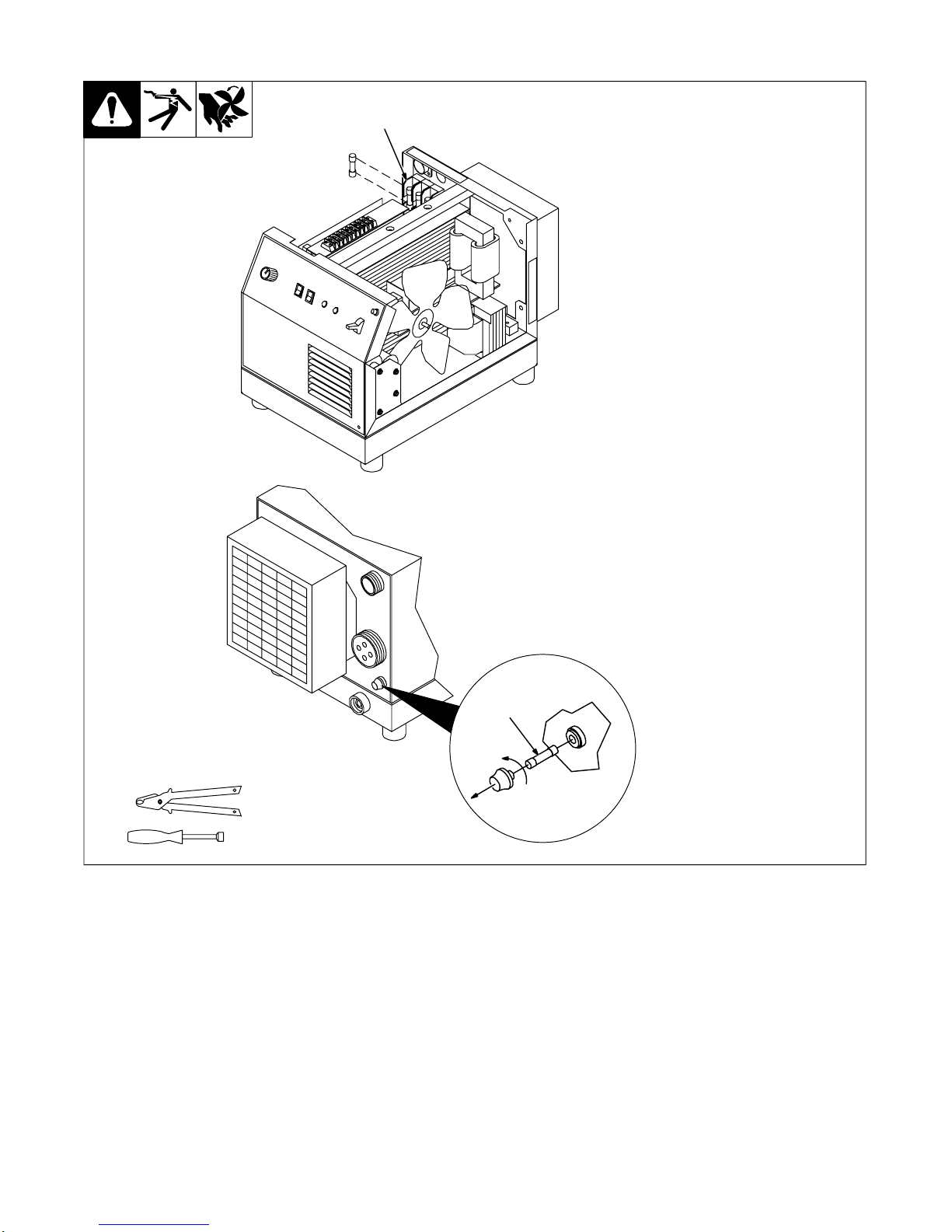
5-6. Safety Interlock Switch And Measuring Tuning Capacitor Voltage
Ref. 802 663
1 Tuning Capacitor Cover
The cover prevents exposure of the
tuningcapacitors on the unit.
2 Safety Interlock Switch
(Behind Cover)
The safety interlock switch
prevents the contactor from
energizingwith the cover open.
To measure capacitor voltage, turn
off power source and disconnect
inputpower.
Open tuning capacitor cover.
3 Tuning Capacitor Assembly
4 Voltmeter
Measure voltage across busbars
every 30 seconds until voltage is
near 0 (zero) volts.
Proceed with job near tuning
capacitor assembly. Close and
secure cover when finished.
Tools Needed:
5/16 in
1
2
4
3
Significant DC voltage can remain on
capacitors after unit is Off. Always
checkcapacitors as shown to be sure
they have discharged before working
on unit.
5-7. Measuring Input Capacitor Voltage
800 998-C
Turn Off power source and
disconnectinput power.
Remove wrapper.
1 Input Capacitor C1
2 Input Capacitor C2
3 Voltmeter
Check input capacitor(s).
Measure the dc voltage across the
positive (+) and negative (–)
terminals every 30 seconds until
voltageis near 0 (zero) volts.
Proceed with job inside unit.
Reinstallwrapper when finished.
Tools Needed:
5/16 in
3
Significant DC voltage can remain on
capacitors after unit is Off. Always
check ALL capacitors as shown to be
sure they have discharged before
working on unit.
1
2
Table of contents
Popular Power Supply manuals by other brands


Ultra Products
Ultra Products ULT31840 Features

Emerson
Emerson Branson LPX instruction manual

digimess
digimess TM2450 operating instructions

TDK-Lambda
TDK-Lambda GXE600 Series instruction manual

PCB Piezotronics
PCB Piezotronics 443B02 Installation and operating manual

Solar Stik
Solar Stik PRO-VERTER 7000-120 instruction manual


