TOHATSU M 40C User manual

MANUAL
OWNER’S
OB No.003-11055-5
M
25H
30H
40C
OWNER’S MANUAL
25H
30H
40C
M
TOHATSU CORPORATION
Address : 5-4, 3-chome, Azusawa, Itabashi-ku,
TOKYO, 174-0051 JAPAN
Phone : TOKYO (03)3966-3117
FAX : TOKYO (03)3966-2951
Website : www.tohatsu.co.jp
003-11055-5 1107NB
Printed in Japan

Copyright © 2011 Tohatsu Corporation. All rights reserved. No part of this manual may
be reproduced or transmitted in any from or by any means without the express written
permission of Tohatsu Corporation.
READ THIS MANUAL BEFORE USING THE OUTBOARD MOTOR. FAILURE TO FOLLOW THE
INSTRUCTIONS AND SAFETY PRECAUTIONS IN THIS MANUAL CAN RESULT IN SERIOUS
INJURY OR DEATH. KEEP THIS MANUAL IN A SAFE LOCATION FOR FUTURE REFERENCE.
!

YOUR TOHATSU OUTBOARD MOTOR
OWNER REGISTRATION AND IDENTIFICATION
Upon purchasing this product, be sure that the WARRANTY CARD is correctly and
completely filled out and mailed to the addressee noted there on. This WARRANTY
CARD identifies you as the legal owner of the product and serves as your warranty
registration.
TO THE EXTENT PERMITTED BY APPLICABLE LAW, YOUR OUTBOARD MOTOR
WILL NOT BE COVERED BY THE APPLICABLE LIMITED WARRANTY, IF THIS
PROCEDURE IS NOT FOLLOWED.
PRE-DELIVERY CHECK
Be sure that the product has been checked by an authorized TOHATSU dealer before
you take delivery.
Limited Warranty
Please refer to the TOHATSU outboard motor Limited warranty provided to you with
this product, the terms and conditions of which, as amended from time to time, are
incorporated by reference into the manual.

Serial Number
In the space below, please record the outboard motor's serial number (indicated both
on the bottom cowl and on the cylinder block). The serial number will be needed in the
event of theft or to quickly identifying the outboard motor type.
Serial Number :
To You, Our Customer
Thank you for selecting a TOHATSU outboard motor. You are now the proud owner of
an excellent outboard motor that will service you for many years to come.
This manual should be read in its entirety and the inspection and maintenance
procedures described later in this manual should be followed carefully. Should a
problem arise with the outboard motor, please follow the troubleshooting procedures
listed at the end of this manual. If the problem persists, contact an authorized
TOHATSU service shop or dealer.
We hope you will enjoy your outboard motor and wish you good luck in your boating
adventures.
TOHATSU CORPORATION

GENERAL SAFETY INFORMATION . . . . . . . . . . . . . . . . . . . . . . . . . . . . . . . . . . . . 8
1 SPECIFICATIONS . . . . . . . . . . . . . . . . . . . . . . . . . . . . . . . . . . . . . . . . . . . . . . . . . . . . 10
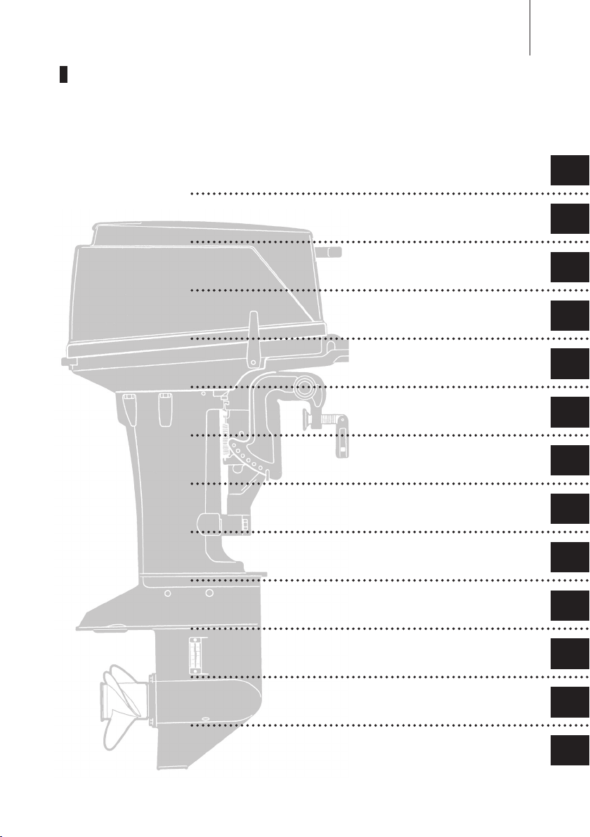
2 NAMES OF PARTS . . . . . . . . . . . . . . . . . . . . . . . . . . . . . . . . . . . . . . . . . . . . . . . . . . . 13
3 INSTALLATION . . . . . . . . . . . . . . . . . . . . . . . . . . . . . . . . . . . . . . . . . . . . . . . . . . . . . . 19
1. Mounting the outboard motor on boat . . . . . . . . . . . . . . . . . . . . . . . . . . . . . . . 19
2. Installing the remote control devices . . . . . . . . . . . . . . . . . . . . . . . . . . . . . . . . . 21
3. Installing the battery . . . . . . . . . . . . . . . . . . . . . . . . . . . . . . . . . . . . . . . . . . . . . . . 25
4 PRE-OPERATING PREPARATIONS . . . . . . . . . . . . . . . . . . . . . . . . . . . . . . . . . . . 27
1. Recommended gasoline types . . . . . . . . . . . . . . . . . . . . . . . . . . . . . . . . . . . . . . 27
2. Recommended engine oil . . . . . . . . . . . . . . . . . . . . . . . . . . . . . . . . . . . . . . . . . . 29
3. Break-in . . . . . . . . . . . . . . . . . . . . . . . . . . . . . . . . . . . . . . . . . . . . . . . . . . . . . . . . . . 31
5 ENGINE OPERATION . . . . . . . . . . . . . . . . . . . . . . . . . . . . . . . . . . . . . . . . . . . . . . . . 32
Before starting . . . . . . . . . . . . . . . . . . . . . . . . . . . . . . . . . . . . . . . . . . . . . . . . . . . . . . 32
1. Starting . . . . . . . . . . . . . . . . . . . . . . . . . . . . . . . . . . . . . . . . . . . . . . . . . . . . . . . . . . 32
2. Warming up the engine . . . . . . . . . . . . . . . . . . . . . . . . . . . . . . . . . . . . . . . . . . . . 36
3. Forward and reverse . . . . . . . . . . . . . . . . . . . . . . . . . . . . . . . . . . . . . . . . . . . . . . . 37
4. Stopping . . . . . . . . . . . . . . . . . . . . . . . . . . . . . . . . . . . . . . . . . . . . . . . . . . . . . . . . . 40
5. Trim angle . . . . . . . . . . . . . . . . . . . . . . . . . . . . . . . . . . . . . . . . . . . . . . . . . . . . . . . . 41
6. Tilt up, tilt down and shallow water operation . . . . . . . . . . . . . . . . . . . . . . . . . 42
6 REMOVING AND CARRYING THE OUTBOARD MOTOR . . . . . . . . . . . . . . . . 45
1. Removing the outboard motor . . . . . . . . . . . . . . . . . . . . . . . . . . . . . . . . . . . . . 45
2. Carrying the outboard motor . . . . . . . . . . . . . . . . . . . . . . . . . . . . . . . . . . . . . . . 45
3. Storing the outboard motor . . . . . . . . . . . . . . . . . . . . . . . . . . . . . . . . . . . . . . . . . 45
7 TRAILERING . . . . . . . . . . . . . . . . . . . . . . . . . . . . . . . . . . . . . . . . . . . . . . . . . . . . . . . . 46
8 ADJUSTMENT . . . . . . . . . . . . . . . . . . . . . . . . . . . . . . . . . . . . . . . . . . . . . . . . . . . . . . . 47
1. Steering friction . . . . . . . . . . . . . . . . . . . . . . . . . . . . . . . . . . . . . . . . . . . . . . . . . . 47
2. Remote control lever load . . . . . . . . . . . . . . . . . . . . . . . . . . . . . . . . . . . . . . . . . . 47
3. Trim tab adjustment . . . . . . . . . . . . . . . . . . . . . . . . . . . . . . . . . . . . . . . . . . . . . . . 48
9 INSPECTION AND MAINTENANCE . . . . . . . . . . . . . . . . . . . . . . . . . . . . . . . . . . . 49
1. Daily inspection . . . . . . . . . . . . . . . . . . . . . . . . . . . . . . . . . . . . . . . . . . . . . . . . . . . 50
2. Periodic inspection . . . . . . . . . . . . . . . . . . . . . . . . . . . . . . . . . . . . . . . . . . . . . . . . 55
3. Off-season storage . . . . . . . . . . . . . . . . . . . . . . . . . . . . . . . . . . . . . . . . . . . . . . . . 58
4. Pre-season check . . . . . . . . . . . . . . . . . . . . . . . . . . . . . . . . . . . . . . . . . . . . . . . . . 59
5. Motor submerged in water . . . . . . . . . . . . . . . . . . . . . . . . . . . . . . . . . . . . . . . . . 60
6. Cold weather precautions . . . . . . . . . . . . . . . . . . . . . . . . . . . . . . . . . . . . . . . . . . 60
7. Checking after striking underwater object . . . . . . . . . . . . . . . . . . . . . . . . . . . . 61
10 TROUBLESHOOTING . . . . . . . . . . . . . . . . . . . . . . . . . . . . . . . . . . . . . . . . . . . . . . . . 62
11 TOOL KIT AND SPARE PARTS . . . . . . . . . . . . . . . . . . . . . . . . . . . . . . . . . . . . . . . 64
12 OPTIONAL ACCESSORIES . . . . . . . . . . . . . . . . . . . . . . . . . . . . . . . . . . . . . . . . . . . 65
13 PROPELLER TABLE . . . . . . . . . . . . . . . . . . . . . . . . . . . . . . . . . . . . . . . . . . . . . . . . . 67
CONTENTS


1
2
3
4
5
6
7
8
9
10
11
12
13
14
7
1. SPECIFICATIONS
2. NAMES OF PARTS
3. INSTALLATION
4.PRE-OPERATING PREPARATIONS
5.ENGINE OPERATION
6.
REMOVING AND CARRYING THE OUTBOARD MOTOR
7.TRAILERING
8.ADJUSTMENT
9.INSPECTION AND MAINTENANCE
10.TROUBLESHOOTING
11.TOOL KIT AND SPARE PARTS
12.OPTIONAL ACCESSORIES
13.PROPELLER TABLE
1
2
3
4
5
6
7
8
9
10
11
12
13
GENERAL SAFETY INFORMATION
INDEX

8
14
13
12
11
10
9
8
7
6
5
4
3
2
1
NOTICE : DANGER/WARNING/CAUTION/Note
Before installing, operating or otherwise handling your outboard motor, be sure
to thoroughly read and understand this Owner's Manual and carefully follow all of
the instructions. Of particular importance is information preceded by the words
"DANGER," "WARNING," "CAUTION," and "Note." Always pay special attention to
such information to ensure safe operation of the outboard motor at all times.
EMERGENCY STOP SWITCH
The Emergency Stop Switch will stall the outboard motor when the stop switch tether
is pulled off. This stop switch tether can be attached to the operator of the outboard
motor to minimize or prevent injuries from the propeller in case the operator falls
overboard.
We highly recommend use of the Emergency Stop Switch tether.
Failure to observe will result in severe personal injury or death, and possibly property damage.
!
Note
This instruction provides special information to facilitate the use or maintenance of the
outboard motor or to clarify important points.
Failure to observe could result in personal injury or property damage.
!
!
Failure to observe could result in severe personal injury or death, or property damage.
GENERAL SAFETY INFORMATION
!
Accidental activation of the Emergency Stop Switch (such as the tether being pulled out
in heavy seas) could cause passengers to lose their balance and even fall overboard,
or it could result in loss of power in heavy seas, strong currents, or high winds. Loss of
control while mooring is another potential hazard.
To minimize accidental activation of the Emergency Stop Switch, the 500 mm (20 inch.)
stop switch tether is coiled and can extended to a full 1,300 mm (51 inch.).

1
2
3
4
5
6
7
8
9
10
11
12
13
14
9
SAFE OPERATION OF BOAT
As the operator/driver of the boat, you are responsible for the safety of those aboard
and those in other boat around yours, and for following local boating regulations. You
should be thoroughly knowledgeable on how to correctly operate the boat, outboard
motor, and accessories. To learn about the correct operation and maintenance of the
outboard motor, please read through this manual carefully.
It is very difficult for a person standing or floating in the water to take evasive action
should he or she see a power boat heading in his /her direction, even at a slow speed.
Therefore, when your boat is in the immediate vicinity of people in the water, the
outboard motor should be shifted to neutral and shut off.
SERVICING, REPLACEMENT PARTS & LUBRICANTS
We recommend that only an authorized service shop perform service or maintenance
on this outboard motor. Be sure to use genuine parts, genuine lubricants, or
recommended lubricants.
MAINTENANCE
As the owner of this outboard motor, you should be acquainted with correct
maintenance procedures. It is the operator's responsibility to perform all safety checks
and to ensure that all lubrication and maintenance instructions are complied with
for safe operation. Please comply with all instructions concerning lubrication and
maintenance. You should take the engine to an authorized dealer or service shop for
periodic inspection at the prescribed intervals.
Correct periodic maintenance and proper care of this outboard motor will reduce the
chance of problems and limit overall operating expenses.
MOUNTING
Outboard motor mounting must be performed by trained service person(s) using lift or
hoist with sufficient capacity.
!
SERIOUS INJURY IS LIKELY IF A PERSON IN THE WATER MAKES CONTACT WITH
A MOVING BOAT, GEAR HOUSING, PROPELLER, OR ANY SOLID DEVICE RIGIDLY
ATTACHED TO A BOAT OR GEAR HOUSING.

10
14
13
12
11
10
9
8
7
6
5
4
3
2
1
SPECIFICATIONS
MODEL 25H 25H EF 25H EP
Item
Overall Length mm (in) 884 (34.8) 600 (23.6)
Overall Width mm (in) 412 (16.2) 355 (14.0)
Overall Height S·L·UL mm (in) 1,124 (44.3) · 1,251 (49.3) · 1,378 (54.3)
Transom Height S·L·UL mm (in) 435 (17.1) · 562 (22.1) · 689 (27.1)
Weight
S kg (lb) 51 (112) 55 (121) 54 (119)
L kg (lb) 52.5 (116) 56.5 (125) 55.5 (122)
UL kg (lb) 54 (119) 58 (128) 57 (126)
Output kW (Hp) 18.4 (25)
Max. Operating Range rpm 5,000-6,000
Number of Cylinder 2
Piston Displacement mL (Cu in) 429 (26.16)
Bore X Stroke mm (in) 68 X 59 (2.68 X 2.32)
Exhaust System Through hub exhaust
Lubrication System Engine Oil Mixed Gasoline
Cooling System Forced water cooling
Starting System Manual Electric starter motor*
Ignition System Flywheel Magneto C.D. Ignition
Spark Plug NGK B7HS-10/BR7HS-10
Alternator 12V, 80W (Max.)
Trim Position 6
Engine Oil Mixing Ratio Unleaded Gasoline 50 : Genuine 2-stroke Engine Oil 1
Gear Oil mL (fl.oz.) Genuine Gear Oil or API GL5,
SAE #80 - #90, Approx. 280 (9.5)
Fuel Tank Capacity L (US gal) 25 (6.6)
Gear Reduction Ratio 1.92 (12 : 23)
* : with manual
Remark :
Specifications subject to change without notice.
25H, 25H EF, 25H EP

SPECIFICATIONS
1
11
30H, 30H EF, 30H EP
MODEL 30H 30H EF 30H EP
Item
Overall Length mm (in) 884 (34.8) 600 (23.6)
Overall Width mm (in) 412 (16.2) 355 (14.0)
Overall Height S·L·UL mm (in) 1,124 (44.3) · 1,251 (49.3) · 1,378 (54.3)
Transom Height S·L·UL mm (in) 435 (17.1) · 562 (22.1) · 689 (27.1)
Weight
S kg (lb) 51 (112) 55 (121) 54 (119)
L kg (lb) 52.5 (116) 56.5 (125) 55.5 (122)
UL kg (lb) 54 (119) 58 (128) 57 (126)
Output kW (Hp) 22.1 (30)
Max. Operating Range rpm 5,150-5,850
Number of Cylinder 2
Piston Displacement mL (Cu in) 429 (26.16)
Bore X Stroke mm (in) 68 X 59 (2.68 X 2.32)
Exhaust System Through hub exhaust
Lubrication System Engine Oil Mixed Gasoline
Cooling System Forced water cooling
Starting System Manual Electric starter motor*
Ignition System Flywheel Magneto C.D. Ignition
Spark Plug NGK B7HS-10/BR7HS-10
Alternator 12V, 80W (Max.)
Trim Position 6
Engine Oil Mixing Ratio Unleaded Gasoline 50 : Genuine 2-stroke Engine Oil 1
Gear Oil mL (fl.oz.) Genuine Gear Oil or API GL5,
SAE #80 - #90, Approx. 280 (9.5)
Fuel Tank Capacity L (US gal) 25 (6.6)
Gear Reduction Ratio 1.92 (12 : 23)
* : with manual
Remark :
Specifications subject to change without notice.

SPECIFICATIONS
12
1
MODEL 40C 40C EF 40C EP
Item
Overall Length mm (in) 919 (36.2) 600 (23.6)
Overall Width mm (in) 415 (16.3) 355 (14.0)
Overall Height S·L·UL mm (in) 1,118 (44.0) · 1,245 (49.0) · 1,372 (54.0)
Transom Height S·L·UL mm (in) 435 (17.1) · 562 (22.1) · 689 (27.1)
Weight
S kg (lb) 59 (130) 62 (137) 60.5 (133)
L kg (lb) 60.5 (133) 63.5 (140) 62 (137)
UL kg (lb) 62 (137) 65 (143) 63.5 (140)
Output kW (Hp) 29.4 (40)
Max. Operating Range rpm 5,200-5,800
Number of Cylinder 2
Piston Displacement mL (Cu in) 493 (30.08)
Bore X Stroke mm (in) 70 X 64 (2.76 X 2.52)
Exhaust System Through hub exhaust
Lubrication System Engine Oil Mixed Gasoline
Cooling System Forced water cooling
Starting System Manual Electric starter motor*
Ignition System Flywheel Magneto C.D. Ignition
Spark Plug NGK B7HS-10/BR7HS-10
Alternator 12V, 80W (Max.)
Trim Position 6
Engine Oil Mixing Ratio Unleaded Gasoline 50 : Genuine 2-stroke Engine Oil 1
Gear Oil mL (fl.oz.) Genuine Gear Oil or API GL5,
SAE #80 - #90, Approx. 420 (14.3)
Fuel Tank Capacity L (US gal) 25 (6.6)
Gear Reduction Ratio 1.92 (13 : 25)
* : with manual
Remark :
Specifications subject to change without notice.
40C 40C EF, 40C EP

1
2
3
4
5
6
7
8
9
10
11
12
13
14
13
NAMES OF PARTS
e
1
2
3
4
5
6
7
8
9
0
p
o
i
u
y
t
r
w
q
a
s
d
l
f
g
h
j
k
1
2
3
4
5
6
7
8
9
0
Tilt Handle
Top Cowl
Cooling Water Check Port
Water Plug
Reverse Lock Lever
Anti Ventilation Plate
Trim Tab
Sub Water Inlet
Water Inlet
Propeller
q
w
e
r
t
y
u
i
o
p
Oil Plug (Lower)
Oil Plug (Upper)
Drive Shaft Housing
Thrust Rod
Clamp Bracket
Clamp Screw
Throttle Grip
Adjust Nut
Shift Lever
Starter Handle
a
s
d
f
g
h
j
k
l
Stop Switch
Choke Knob
Fuel Connector
Primer Bulb
Fuel Connector
Fuel Tank Cap
Air Vent Screw
Fuel Pick up Elbow
Fuel Tank
25H, 30H

NAMES OF PARTS
14
2
s
d
f
a
h
j
k
l
;
e
1
2
3
4
5
6
7
8
9
0
p
o
i
u
y
t
r
w
q
g
z
1
2
3
4
5
6
7
8
9
0
q
Tilt Handle
Top Cowl
Cooling Water Check Port
Water Plug
Reverse Lock Lever
Anti Ventilation Plate
Trim Tab
Sub Water Inlet
Water Inlet
Propeller
Oil Plug (Lower)
w
e
r
t
y
u
i
o
p
a
s
Oil Plug (Upper)
Drive Shaft Housing
Thrust Rod
Clamp Bracket
Clamp Screw
Throttle Grip
Adjust Nut
Shift Lever
Starter Handle
Battery Cable
Stop Switch
d
f
g
h
j
k
l
;
z
Choke Knob
Main Switch
Fuel Connector
Primer Bulb
Fuel Connector
Fuel Tank Cap
Air Vent Screw
Fuel Pick up Elbow
Fuel Tank
25H EF, 30H EF

NAMES OF PARTS
2
15
25H EP, 30H EP
j
k
l
;
e
1
2
3
4
5
6
7
8
9
0
i
u
y
t
r
w
q
f
g
h
o
p
a
s
d
1
2
3
4
5
6
7
8
9
0
Tilt Handle
Top Cowl
Cooling Water Check Port
Water Plug
Reverse Lock Lever
Anti Ventilation Plate
Trim Tab
Sub Water Inlet
Water Inlet
Propeller
q
w
e
r
t
y
u
i
o
p
Oil Plug (Lower)
Oil Plug (Upper)
Drive Shaft Housing
Thrust Rod
Clamp Bracket
Clamp Screw
Shift Lever
Starter Handle
Battery Cable
Fuel Connector
a
s
d
f
g
h
j
k
l
;
Primer Bulb
Fuel Connector
Fuel Tank Cap
Air Vent Screw
Fuel Pick up Elbow
Fuel Tank
Remote Control
Main Switch
Stop Switch
Cord Assembly

NAMES OF PARTS
16
2
o
i
u
y
t
r
e
q
8
0
w
1
2
3
4
5
6
7
9
p
as
k
d
f
g
h
j
1
2
3
4
5
6
7
8
9
0
Tilt Handle
Top Cowl
Cooling Water Check Port
Water Plug
Reverse Lock Lever
Anti Ventilation Plate
Trim Tab
Water Inlet
Propeller
Oil Plug (Lower)
q
w
e
r
t
y
u
i
o
p
Oil Plug (Upper)
Drive Shaft Housing
Thrust Rod
Clamp Bracket
Clamp Screw
Throttle Grip
Adjust Nut
Shift Lever
Starter Handle
Stop Switch
a
s
d
f
g
h
j
k
Choke Knob
Fuel Connector
Primer Bulb
Fuel Connector
Fuel Tank Cap
Air Vent Screw
Fuel Pick up Elbow
Fuel Tank
40C

NAMES OF PARTS
2
17
w
1
2
3
4
5
6
7
9
o
i
a
u
y
t
r
e
p
8
q
0
d
s
f
;
gh
j
k
l
1
2
3
4
5
6
7
8
9
0
Tilt Handle
Top Cowl
Cooling Water Check Port
Water Plug
Reverse Lock Lever
Anti Ventilation Plate
Trim Tab
Water Inlet
Propeller
Oil Plug (Lower)
q
w
e
r
t
y
u
i
o
p
Oil Plug (Upper)
Drive Shaft Housing
Thrust Rod
Clamp Bracket
Clamp Screw
Throttle Grip
Adjust Nut
Shift Lever
Starter Handle
Battery Cable
a
s
d
f
g
h
j
k
l
;
Stop Switch
Choke Knob
Main Switch
Fuel Connector
Primer Bulb
Fuel Connector
Fuel Tank Cap
Air Vent Screw
Fuel Pick up Elbow
Fuel Tank
40C EF

NAMES OF PARTS
18
2
40C EP
u
y
t
r
e
i
8
q
0
w
1
2
3
4
5
6
7
9
o
g
p
a
s
d
f
h
j
k
l
1
2
3
4
5
6
7
8
9
0
Tilt Handle
Top Cowl
Cooling Water Check Port
Water Plug
Reverse Lock Lever
Anti Ventilation Plate
Trim Tab
Water Inlet
Propeller
Oil Plug (Lower)
q
w
e
r
t
y
u
i
o
p
Oil Plug (Upper)
Drive Shaft Housing
Thrust Rod
Clamp Bracket
Clamp Screw
Shift Lever
Starter Handle
Battery Cable
Fuel Connector
Primer Bulb
a
s
d
f
g
h
j
k
l
Fuel Connector
Fuel Tank Cap
Air Vent Screw
Fuel Pick up Elbow
Fuel Tank
Remote Control
Main Switch
Stop Switch
Cord Assembly

■ Single-engine Installation
Set engine at center of boat.
■ Twin-engine Installation
When installing two outboard
engines, be sure to keep an interval
of approximately 580 mm (22.8 in)
between the two.
Transom matching
1 Be sure that the anti ventilation plate
of the outboard motor is 30-50mm
(1.2-2 in) below the bottom of hull.
If the above condition cannot be
met due to the shape of the bottom
of your boat, please consult your
authorized dealer.
2 To attach the outboard motor to the
boat, tighten the clamp screws by
turning their handles.
Also, use the bolts to secure
the outboard motor brackets on
transom board.
Secure the outboard motor with a
rope to prevent loss overboard.
1
2
3
4
5
6
7
8
9
10
11
12
13
14
19
!
Most boats are rated and certified
in terms of their maximum allowable
horsepower, as shown on the boat’s
certification plate. Do not equip your boat
with an outboard motor that exceeds this
limit. If in doubt, contact your dealer.
Do not operate the outboard motor until it
has been securely mounted on the boat
in accordance with the instructions below.
1.
Mounting the outboard motor on boat
INSTALLATION
Boat Transom
Center of Boat
Bottom of hull
Anti Ventilation Plate
30-50 mm
(1.2-2 in)
Approx.580 mm (22.8 in)
Note
A rope is not included in the standard
accessories.
Bolt
Clamp
screw
Nut &
Washer
*option
Washer

INSTALLATION
20
3
• Before beginning the running test,
check that the boat with maximum
capacity loading floats on the
water in a proper attitude. Check
the position of water surface on
the driveshaft housing. If the water
surface is near the bottom cowling,
in high waves, water may enter the
engine cylinders.
• Incorrect outboard motor mounting
height or existence of underwater
object(s), such as hull bottom
design, bottom surface conditions
or underwater accessories, can
cause water spray possibly reaching
the engine through an opening of
the bottom cowling during cruising.
Exposing the engine to such
conditions for extended periods can
lead to severe engine damage.
!
Mounting bolts should be installed with
the bolt head at inside surface of the
transom. Mounting bolts installed with
the threaded end at the inside surface of
the transom can cause personal injury.
!
Notes
1. Apply sealing agent, such as
silicone sealed between the bolts
and the transom board holes before
tightening the bolts.
2. Be sure to tighten the mounting bolt
nuts to the specified torque.
(30 Nm (3.0kgf)13ft · lb)
!
• Mounting the outboard motor without
following this manual can lead to
unsafe conditions such as poor
maneuverability, lack of control or fire.
• Loose clamp screws and/or mounting
bolts can lead to the release or
displacement of the outboard motor,
possibly resulting in lost of control
and/or serious personal injury. Be sure
that fasteners are tightened to the
specified torque (30 Nm (3.0kgf) 13ft·lb).
Check the fasteners for tightness from
time to time.
•
Be sure to use outboard mounting
fasteners included in the outboard
motor package or their equivalents
in terms of size, material, quality
and strength.
Tighten fasteners to the specified
torque (30 Nm (3.0kgf) 13ft·lb).
Test cruise to check if fasteners
are tightened securely.
•
Outboard motor mounting must
be performed by trained service
person(s) using lift or hoist with
sufficient capacity.
Table of contents
Other TOHATSU Outboard Motor manuals

TOHATSU
TOHATSU 2 Stroke 60C EF User manual

TOHATSU
TOHATSU M 6B User manual

TOHATSU
TOHATSU MFS 2.5B User manual

TOHATSU
TOHATSU 8 User manual

TOHATSU
TOHATSU MFS 25 User manual

TOHATSU
TOHATSU MFS 40A User manual

TOHATSU
TOHATSU 2 Stroke 3.5A Mounting instructions

TOHATSU
TOHATSU MFS 25d User manual

TOHATSU
TOHATSU BFT200A User manual

TOHATSU
TOHATSU MFS 8B User manual

TOHATSU
TOHATSU mfs 20D User manual

TOHATSU
TOHATSU 9.9D User manual

TOHATSU
TOHATSU BFT 200D Quick start guide

TOHATSU
TOHATSU M 25 User manual

TOHATSU
TOHATSU MFS 4 User manual

TOHATSU
TOHATSU MFS 5D LPG User manual

TOHATSU
TOHATSU MFS 4C User manual

TOHATSU
TOHATSU MFS 40A User manual

TOHATSU
TOHATSU mfs 15D User manual

TOHATSU
TOHATSU 5 B User manual