TOHATSU MFS 4B User manual

4B
5B
6B
MFS
OB No.003-11059-6
MANUAL
OWNER’S

Copyright © 2009 Tohatsu Corporation. All rights reserved. No part of this manual may
be reproduced or transmitted in any from or by any means without the express written
permission of Tohatsu Corporation.
READ THIS MANUAL BEFORE USING THE OUTBOARD MOTOR. FAILURE TO FOLLOW THE
INSTRUCTIONS AND SAFETY PRECAUTIONS IN THIS MANUAL CAN RESULT IN SERIOUS
INJURY OR DEATH. KEEP THIS MANUAL IN A SAFE LOCATION FOR FUTURE REFERENCE.
!

YOUR TOHATSU OUTBOARD MOTOR
OWNER REGISTRATION AND IDENTIFICATION
Upon purchasing this product, be sure that the WARRANTY CARD is correctly and
completely filled out and mailed to the addressee noted there on. This WARRANTY
CARD identifies you as the legal owner of the product and serves as your warranty
registration.
IF THIS PROCEDURE IS NOT FOLLOWED, YOUR OUTBOARD MOTOR WILL
NOT BE COVERED BY THE APPLICABLE LIMITED WARRANTY.
PRE-DELIVERY CHECK
Be sure that the product has been checked by an authorized TOHATSU dealer
before you take delivery.
Limited Warranty
Please refer to the TOHATSU outboard motor Limited warranty provided to you with
this product, the terms and conditions of which, as amended from time to time, are
incorporated by reference into the manual.

Serial Number
In the space below, please record the outboard motor's serial number (indicated
both on the lower motor cover and on the cylinder block). The serial number will be
needed in the event of theft or to quickly identifying the outboard motor type.
Serial Number :
To You, Our Customer
Thank you for selecting a TOHATSU outboard motor. You are now the proud owner
of an excellent outboard motor that will service you for many years to come.
This manual should be read in its entirety and the inspection and maintenance
procedures described later in this manual should be followed carefully. Should
a problem arise with the outboard motor, please follow the troubleshooting
procedures listed at the end of this manual. If the problem persists, contact an
authorized TOHATSU service shop or dealer.
We hope you will enjoy your outboard motor and wish you good luck in your
boating adventures.
TOHATSU CORPORATION

GENERAL SAFETY INFORMATION・・・・・・・・・・・・・・・・・・・・・・・・・・・・・・・・・・・
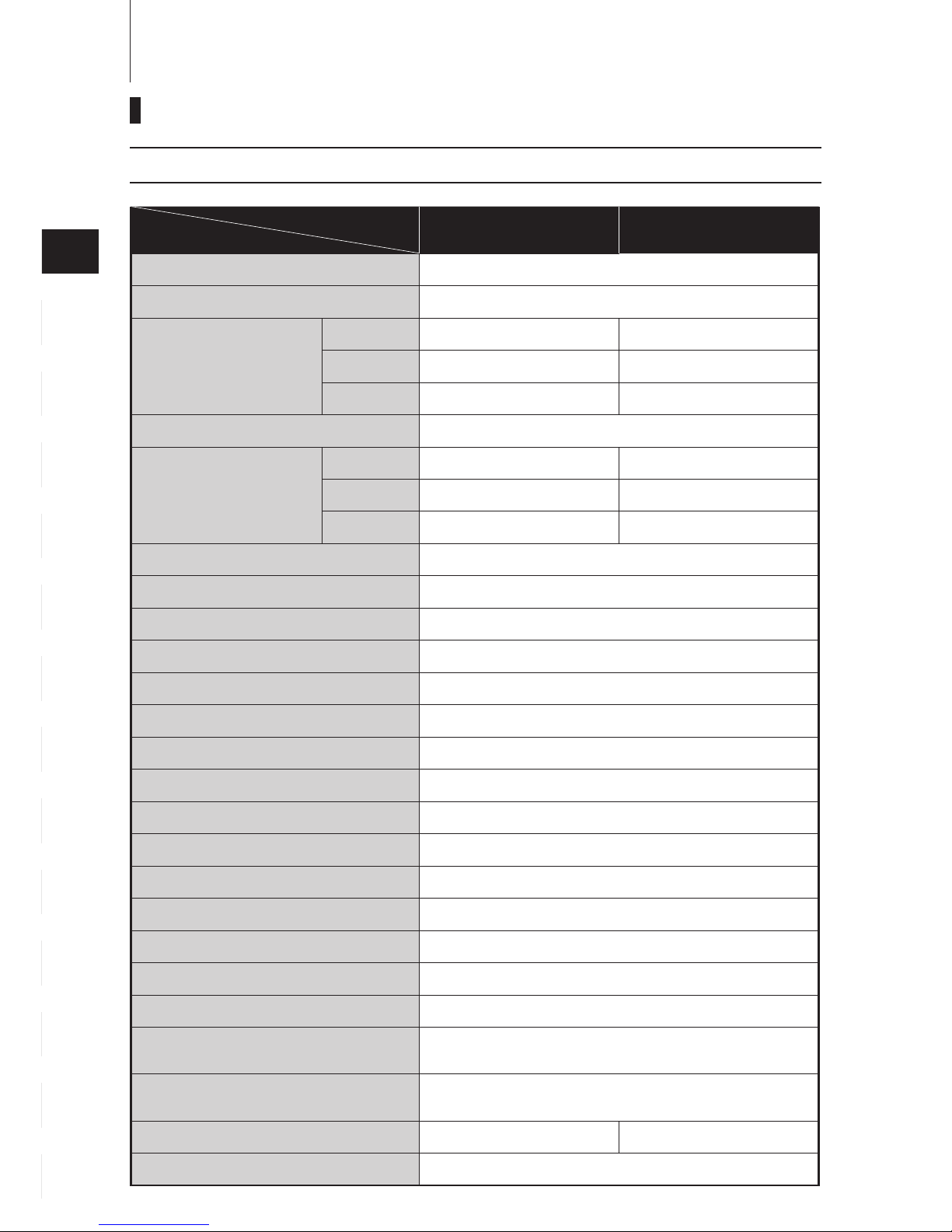
SPECIFICATIONS・・・・・・・・・・・・・・・・・・・・・・・・・・・・・・・・・・・・・・・・・・・・・・・・・・・
NAMES OF PARTS・・・・・・・・・・・・・・・・・・・・・・・・・・・・・・・・・・・・・・・・・・・・・・・・・・
INSTALLATION・・・・・・・・・・・・・・・・・・・・・・・・・・・・・・・・・・・・・・・・・・・・・・・・・・・・・
1. Mounting the outboard motor on boat・・・・・・・・・・・・・・・・・・・・・・・・・・・・・・・
PRE-OPERATING PREPARATIONS・・・・・・・・・・・・・・・・・・・・・・・・・・・・・・・・・・・
1.Gasoline and engine oil・・・・・・・・・・・・・・・・・・・・・・・・・・・・・・・・・・・・・・・・・・・・
2.Break-in・・・・・・・・・・・・・・・・・・・・・・・・・・・・・・・・・・・・・・・・・・・・・・・・・・・・・・・・・
3.Engine oil warning lamp ・・・・・・・・・・・・・・・・・・・・・・・・・・・・・・・・・・・・・・・・・・・
4.ESG ・・・・・・・・・・・・・・・・・・・・・・・・・・・・・・・・・・・・・・・・・・・・・・・・・・・・・・・・・・・・
ENGINE OPERATION・・・・・・・・・・・・・・・・・・・・・・・・・・・・・・・・・・・・・・・・・・・・・・・・
Before starting・・・・・・・・・・・・・・・・・・・・・・・・・・・・・・・・・・・・・・・・・・・・・・・・・・・・・
1.Starting・・・・・・・・・・・・・・・・・・・・・・・・・・・・・・・・・・・・・・・・・・・・・・・・・・・・・・・・・・
2.Warming up the engine・・・・・・・・・・・・・・・・・・・・・・・・・・・・・・・・・・・・・・・・・・・・
3.Forward and reverse・・・・・・・・・・・・・・・・・・・・・・・・・・・・・・・・・・・・・・・・・・・・・・
4.Stopping・・・・・・・・・・・・・・・・・・・・・・・・・・・・・・・・・・・・・・・・・・・・・・・・・・・・・・・・・
5.Trim angle・・・・・・・・・・・・・・・・・・・・・・・・・・・・・・・・・・・・・・・・・・・・・・・・・・・・・・・
6.Tilt up, tilt down and shallow water operation ・・・・・・・・・・・・・・・・・・・・・・・・・
7.Shallow water operation・・・・・・・・・・・・・・・・・・・・・・・・・・・・・・・・・・・・・・・・・・・
REMOVING AND CARRYING THE OUTBOARD MOTOR・・・・・・・・・・・・・・・・
1.Removing the outboard motor・・・・・・・・・・・・・・・・・・・・・・・・・・・・・・・・・・・・・・
2.Carrying the outboard motor・・・・・・・・・・・・・・・・・・・・・・・・・・・・・・・・・・・・・・・・
3.Storing the outboard motor・・・・・・・・・・・・・・・・・・・・・・・・・・・・・・・・・・・・・・・・・
TRAILERING・・・・・・・・・・・・・・・・・・・・・・・・・・・・・・・・・・・・・・・・・・・・・・・・・・・・・・・
ADJUSTMENT・・・・・・・・・・・・・・・・・・・・・・・・・・・・・・・・・・・・・・・・・・・・・・・・・・・・・・
1.Steering friction・・・・・・・・・・・・・・・・・・・・・・・・・・・・・・・・・・・・・・・・・・・・・・・・・・・
2.Throttle grip・・・・・・・・・・・・・・・・・・・・・・・・・・・・・・・・・・・・・・・・・・・・・・・・・・・・・・
3.Reverse lock・・・・・・・・・・・・・・・・・・・・・・・・・・・・・・・・・・・・・・・・・・・・・・・・・・・・・
INSPECTION AND MAINTENANCE・・・・・・・・・・・・・・・・・・・・・・・・・・・・・・・・・・・
1.Daily inspection・・・・・・・・・・・・・・・・・・・・・・・・・・・・・・・・・・・・・・・・・・・・・・・・・・・
2.Periodic inspection・・・・・・・・・・・・・・・・・・・・・・・・・・・・・・・・・・・・・・・・・・・・・・・・
3.Off-season storage・・・・・・・・・・・・・・・・・・・・・・・・・・・・・・・・・・・・・・・・・・・・・・・・
4.Pre-season check・・・・・・・・・・・・・・・・・・・・・・・・・・・・・・・・・・・・・・・・・・・・・・・・・
5.Motor submerged in water ・・・・・・・・・・・・・・・・・・・・・・・・・・・・・・・・・・・・・・・・・
6.Cold weather precautions・・・・・・・・・・・・・・・・・・・・・・・・・・・・・・・・・・・・・・・・・・
7.Checking after striking underwater object ・・・・・・・・・・・・・・・・・・・・・・・・・・・・
TROUBLESHOOTING・・・・・・・・・・・・・・・・・・・・・・・・・・・・・・・・・・・・・・・・・・・・・・・
TOOL KIT AND SPARE PARTS・・・・・・・・・・・・・・・・・・・・・・・・・・・・・・・・・・・・・・・
OPTIONAL ACCESSORIES・・・・・・・・・・・・・・・・・・・・・・・・・・・・・・・・・・・・・・・・・・
PROPELLER TABLE・・・・・・・・・・・・・・・・・・・・・・・・・・・・・・・・・・・・・・・・・・・・・・・・
■
■
■
■
■
■
■
■
■
■
■
■
■
■
1
2
3
4
5
6
7
8
9
10
11
12
13
8
10
11
12
12
14
14
16
17
17
18
18
18
21
22
23
24
25
26
28
28
28
28
29
30
30
30
30
31
32
37
41
42
43
43
44
45
48
49
50
CONTENTS


7
1
2
3
4
5
6
7
8
9
10
11
12
13
1. SPECIFICATIONS
2. NAMES OF PARTS
3. INSTALLATION
4.PRE-OPERATING PREPARATIONS
5.ENGINE OPERATION
6.
REMOVING AND CARRYING THE MOTOR
7.TRAILERING
8.ADJUSTMENT
9.INSPECTION AND MAINTENANCE
10.TROUBLESHOOTING
11.TOOL KIT AND SPARE PARTS
12.OPTIONAL ACCESSORIES
13.PROPELLER TABLE
INDEX
GENERAL SAFETY INFORMATION

NOTICE : DANGER/WARNING/CAUTION/Note
Before installing, operating or otherwise handling your outboard motor, be sure
to thoroughly read and understand this Owner's Manual and carefully follow all of
the instructions. Of particular importance is information preceded by the words
"DANGER," "WARNING," "CAUTION," and "Note." Always pay special attention to
such information to ensure safe operation of the outboard motor at all times.
EMERGENCY STOP SWITCH
The Emergency Stop Switch will stall the outboard motor when the stop switch
tether is pulled off. This stop switch tether can be attached to the operator of
the outboard motor to minimize or prevent injuries from the propeller in case the
operator falls overboard.
We highly recommend use of the Emergency Stop Switch tether.
Failure to observe will result in severe personal injury or death, and possibly property damage.
!
Note
This instruction provides special information to facilitate the use or maintenance of the
outboard motor or to clarify important points.
Failure to observe could result in personal injury or property damage.
!
!
Failure to observe could result in severe personal injury or death, or property damage.
GENERAL SAFETY INFORMATION
!
Accidental activation of the Emergency Stop Switch (such as the tether being pulled out
in heavy seas) could cause passengers to lose their balance and even fall overboard, or it
could result in loss of power in heavy seas, strong currents, or high winds. Loss of control
while mooring is another potential hazard.
To minimize accidental activation of the Emergency Stop Switch, the 500 mm (20 inch.)
stop switch tether is coiled and can extended to a full 1,300 mm (51 inch.).

SAFE OPERATION OF BOAT
As the operator/driver of the boat, you are responsible for the safety of those
aboard and those in other boat around yours, and for following local boating
regulations. You should be thoroughly knowledgeable on how to correctly operate
the boat, outboard motor, and accessories. To learn about the correct operation
and maintenance of the outboard motor, please read through this manual carefully.
It is very difficult for a person standing or floating in the water to take evasive action
should he or she see a power boat heading in his /her direction, even at a slow
speed. Therefore, when your boat is in the immediate vicinity of people in the water,
the outboard motor should be shifted to neutral and shut off.
SERVICING, REPLACEMENT PARTS & LUBRICANTS
We recommend that only an authorized service shop perform service or
maintenance on this outboard motor. Be sure to use genuine parts, genuine
lubricants, or recommended lubricants.
MAINTENANCE
As the owner of this outboard motor, you should be acquainted with correct
maintenance procedures. It is the operator's responsibility to perform all safety
checks and to ensure that all lubrication and maintenance instructions are
complied with for safe operation. Please comply with all instructions concerning
lubrication and maintenance. You should take the engine to an authorized dealer
or service shop for periodic inspection at the prescribed intervals.
Correct periodic maintenance and proper care of this outboard motor will reduce
the chance of problems and limit overall operating expenses.
MOUNTING
Outboard motor mounting must be performed by trained service person(s) using
lift or hoist with sufficient capacity.
!
SERIOUS INJURY IS LIKELY IF A PERSON IN THE WATER MAKES CONTACT WITH
A MOVING BOAT, GEAR HOUSING, PROPELLER, OR ANY SOLID DEVICE RIGIDLY
ATTACHED TO A BOAT OR GEAR HOUSING.

MODEL
Item
4B(D) 5B(D) M6B(D)
(Integral Tank)
5B(S) 6B(S)
(Separate Tank)
Overall Length mm (in) 680 (26.8)
Overall Width mm (in) 325 (12.8)
Overall Height S·L·UL
S mm (in) 1,073 (42.2) 1,020 (40.2)
L mm (in) 1,200 (47.2) 1,147 (45.2)
UL mm (in) 1,327 (52.2) 1,274 (50.2)
Transom Height S·L·UL mm (in) 435 (17.1) · 562 (22.1) · 689 (27.1)
Weight
S Kg (lb) 26 (57) 25 (55)
L Kg (lb) 27 (59) 26 (57)
UL Kg (lb) 28 (61) 27 (59)
Output kW (Hp) 4B : 2.9 (4) 5B : 3.7 (5) 6B : 4.4 (6)
Max. Operating Range rpm 4B & 5B : 4,500 - 5,500 6B :5,000 - 6,000
Idle Speed in Forward Gear rpm 1,100
Idle Speed in Neutral Gear rpm 1,300
Engine Type 4-Stroke
Number of Cylinder 1
Bore × Stroke mm (in) 59 × 45 (2.32 × 1.77)
Piston Displacement mL (Cu in) 123 (7.5)
Exhaust System Through hub exhaust
Cooling System Water cooling
Engine Lubrication Trochoid pump
Startring System Manual Starter
Ignition System Flywheel Magneto C.D. ignition
Spark Plug NGK DCPR6E
Trim Position 6
Engine Oil API SF, SG, SH or SJ
FCW 10W-30/40, Approx. 450 (15.2)
Gear Oil Genuine Gear Oil or API GL5,
SAE #80-90, Approx. 195mL
Fuel Tank Capacity L (US gal) *1.3 (0.34) Integral 12 (3.17) Separate
Gear Reduction Ratio 2.15 (13 : 28)
*
In case of dual fuel tank system, use it together with 12L separate tank.
10
14
13
12
11
10
9
8
7
6
5
4
3
2
1
MF , EF , EP
SPECIFICATIONS

Dual fuel tank
Integral fuel tank
○
1
○
2
○
3
○
8
○
9
○
11
○
10
○
13
○
14
○
15
○
16
○
17
○
18
○
23
○
20
○
19
○
21
○
22
○
12
○
4
○
5
○
6
○
7
○
24
○
25
○
26
○
27
○
29
○
30
○
31
○
32
○
33
○
34
○
28
○
25
①
②
③
④
⑤
⑥
⑦
⑧
⑨
⑩
○
11
○
12
○
13
Tilt Handle
Top Cowl
Lower Motor Cover
Cooling Water Check Port
Tilt Lever
Steering Adjustment Screw
Anode
Anti Ventilation Plate
Propeller
Oil Plug (Lower) (Fill)
Water Inlet
Oil Plug (Upper) (Level)
Thrust Rod
○
14
○
15
○
16
○
17
○
18
○
19
○
20
○
21
○
22
○
23
○
24
○
25
○
26
Clamp Bracket
Clamp Screw
Throttle Grip
Shift Lever
Starter Handle
Choke Knob
Stop Switch
Fuel Connector
Warning Lamp
Air Vent Screw
Fuel Connector
Fuel Cock
Primer Bulb
○
27
○
28
○
29
○
30
○
31
○
32
○
33
○
34
Fuel Tank
Fuel Pick up Elbow
Fuel Connector
Air Vent Screw
Fuel Tank Cap
Engine Oil Filter Cap
Spark Plug
Engine Oil Drain Screw
11
1
2
3
4
5
6
7
8
9
10
11
12
13
4B , 5B , 6B
NAMES OF PARTS

Bottom of hull
Anti Ventilation Plate
30-50mm
(1.2-2”)
Position ... Above keel line
Set engine at center of boat.
Transom matching
Be sure that the anti ventilation plate of
the outboard motor is below the water
surface when running with the throttle
wide open.
If the above condition cannot be met
due to the shape of the bottom of your
boat, please consult your authorized
dealer.
12
14
13
12
11
10
9
8
7
6
5
4
3
2
1
!
Most boats are rated and certified
in terms of their maximum allowable
horsepower, as shown on the boat’s
certification plate. Do not equip your boat
with an outboard motor that exceeds this
limit. If in doubt, contact your dealer.
Do not operate the outboard motor until it
has been securely mounted on the boat
in accordance with the instructions below.
1. Mounting the outboard motor on boat
INSTALLATION
Boat Transom
Center of Boat
●Before beginning the running test,
check that the boat with maximum
capacity loading floats on the water in
a proper attitude. Check the position
of water surface on the driveshaft
housing. If the water surface is near
the bottom cowling, in high waves,
water may enter the engine cylinders.
●Incorrect outboard motor mounting
height or existence of underwater
object(s), such as hull bottom
design, bottom surface conditions or
underwater accessories, can cause
production of water spray possibly
reaching the engine through an
opening of the bottom cowling
during cruising. Exposing engine
to such conditions for extended
periods can lead to severe engine
damage.
!

①To attach the outboard motor to the
boat, tighten the clamp screws by
turning their handles.
Secure the outboard motor with a
rope to prevent loss overboard.
13
1
2
3
4
5
6
7
8
9
10
11
12
13
Note
It is recommended to install upper
mounting bolts with bolt head at
inside surface of transom. Bolts with
threaded end at inside surface of
transom can cause personal injury.
INSTALLATION
Note
The rope is not included in the standard
accessories.
!
●Mounting outboard motor without
following this manual can lead to unsafe
conditions such as poor maneuverability,
going out of control or fire disaster.
●Loose clamp screws and/or mounting
bolts can lead to coming off or
displacement of outboard motor,
possibly going out of control or causing
serious personal injury. Be sure that
fasteners are tightened to the specified
torque (30 Nm (3.0kgf)13ft·lb). Check
fasteners for tightness from time to time.
●Be sure to use outboard mounting
fasteners included in outboard motor
package delivered or their equivalents
in terms of size, material, quality and
strength.
Tighten fasteners to the specified torque
(30 Nm (3.0kgf)13ft·lb). Test cruise
to check if fasteners are tightened
securely.
●Outboard motor mounting must be
performed by trained service person(s)
using lift or hoist with sufficient capacity.
Clamp Screw
*: Option

Required Gasoline types
UNITED STATES AND CANADA:
Use a major brand of automotive
unleaded gasoline with a minimum
posted octane rating of 87. Mid-
grade automotive gasoline that
contain fuel injector cleaner are
preferred for added internal engine
cleanliness. Leaded gasoline is not
recommended.
INTERNATIONAL :
Use a major brand of automotive
unleaded gasoline with a minimum
posted octane rating of 91RON.
Automotive gasoline that contain
fuel injector cleaner are preferred for
added internal engine cleanliness.
Leaded gasoline is acceptable in
areas where unleaded gasoline is not
available.
14
14
13
12
11
10
9
8
7
6
5
4
3
2
1
1. Gasoline and engine oil
Note
Use of low-quality gasoline results in
a short engine life as well as starting
difficulties and other engine problems.
We recommend use for Fuel stabilizer.
PRE-OPERATING PREPARATIONS
!
Do not fill the fuel tank over capacity.
The rise of gasoline temperature may
cause gasoline to expand which, if
overfilled, may leak through an air vent
screw when it is open. Leaking gasoline
is a dangerous fire hazard.
Consult an authorized dealer for details
on handling of gasoline, if necessary.
Gasoline and its vapors are very
flammable and can be explosive.
When carrying a fuel tank containing
gasoline :
●Close the air vent screw of fuel
tank cap, or gasoline vapor will be
emitted through the air vent screw,
creating a fire hazard.
●Do not smoke.
When or before refueling :
●Stop the engine, and do not start the
engine during refueling.
●Do not smoke.
●Be careful not to overfill fuel tank.
Wipe up any spilled gasoline
immediately.
When or before cleaning the gasoline tank :
●Dismount fuel tank from the boat.
●Place the fuel tank away from every
source of ignition, such as sparks or
open flames.
●Do the work outdoors or in well
ventilated area.
●Wipe up any spilled gasoline
immediately.
After cleaning gasoline tank :
●Wipe up any spilled gasoline
immediately.
●If the fuel tank is disassembled for
cleaning, reassemble carefully.
Imperfect assembly may cause a
fuel leak, possibly leading to fire or
explosion.
●Dispose of aged or contaminated
gasoline in accordance with local
regulations.
!

Engine Oil
Use only high quality 4-stroke
engine oil to insure performance and
prolonged engine life.
Use NMMA FC-W certified 4-stroke
engine oil below.
10W-30: is recommended for use in
all temperature.
25W-40: may be used at temperatures
above 4˚C (40˚F).
You can also use oils that carry the
API rating of SF, SG, SH, SJ, SL, or
SM. Select the appropriate viscosity,
based on atmospheric temperature,
from the chart below.
15
1
2
3
4
5
6
7
8
9
10
11
12
13
PRE-OPERATING PREPARATIONS
Note
Use of engine oils that do not meet
these requirements will result in
reduced engine life, and other engine
problems.
THE ENGINE OIL IS DRAINED FOR
SHIPPING FROM THE FACTORY. BE
SURE TO FILL THE ENGINE TO THE
PROPER LEVEL BEFORE STARTING
ENGINE. (TO PROPERLY FILL THE
ENGINE WITH OIL FOLLOW THE
INSTRUCTIONS IN SECTION 9 OF
THIS MANUAL)
!
20W−40, 20W−50
15W−40, 15W−50
10W−40, 10W−50
10W−30
Atmospheric temp.
˚C
˚F
40
96
30
86
20
68
10
50
0
32
-10
14
-20
-4
-30
-22
ENGINE
OIL

Your new outboard motor and lower
unit require break-in for the moving
components according to the
conditions described in the following
time table.
1-10min 10min-2hrs 2-3hrs 3-10hrs After 10hrs
Throttle Position Idle Less than 1/2
throttle
Less than 3/4
throttle 3/4 throttle Full throttle
available
Speed Approx.
3,000 rpm max
Full throttle run
allowed for 1 min
every 10 min
Approx.
4,000 rpm.
Full throttle run
allowed for 2 min
every 10 min
16
14
13
12
11
10
9
8
7
6
5
4
3
2
1
2. Break-in
Note
Proper break-in allows outboard
motor to deliver it full performance for
longer service life.
Operating the outboard motor without
break-in can shorten service life of the
product.
If any abnormality is experienced
during the break-in:
●Discontinue the operation
immediately.
●Have the dealer check the product
and take proper action(s) if
necessary.
!
PRE-OPERATING PREPARATIONS
Do not operate the outboard motor
in closed area or area with no forced
ventilation.
Exhaust gas emitted by this outboard
motor contains carbon monoxide that
will cause death if inhaled continuously.
Inhaling the gas initially causes
symptoms such as feeling of sickness,
drowsiness and headache.
During operation of the outboard motor:
●Keep peripheral area well ventilated.
●Always attempt to stay on the
windward side of emission.
!

Oil pressure is required to lubricate
internal engine parts.
When the warning lamp (Red) is off, it
indicates that oil pressure is present.
Remark : When engine is first started,
the red light will turn on for several
seconds to confirm that it is working
and then turn off.
When the warning lamp is on or
blinking on and off, as an additional
alert of the low oil pressure condition.
*Stop the engine immediately and
check the engine oil level.
If the oil level is lower than the
appropriate level : Replenish engine
oil.
If the oil level is within the appropriate
level : Consult with your dealer.
ESG is a device to prevent over
revolution of the engine (more than
approximately 6,250 rpm).
If you sense that the ESG is activated
return to shore at a reduced speed
(rpm).
Possible causes of ESG activation
are : Worn, broken, bent propeller.
Slipping propeller rubber, Making
sharp turns at high speeds.
17
1
2
3
4
5
6
7
8
9
10
11
12
13
PRE-OPERATING PREPARATIONS
3. Engine oil warning lamp
Note
If the engine speed drops frequently
after restarting the engine, please
contact your dealer.
Never run the engine if the warning
lamp is on or blinking on and off.
!
4. ESG
(A device preventing over revolution)
Warning lamp

Air Vent Screw
Air Vent Screw
Fuel Cock
Before starting engine for the first time
after reassembling engine or off-season
storage, disconnect stop switch lock
and pull the starter handle completely
out approximately 10 times in order to
prime the oil pump.
① Loosen the air vent screw on the
tank cap.
② Attach the fuel connector to the
engine connector.
The arrow mark on the primer
bulb should be facing the
engine.(Separate fuel tank)
Open the fuel cock.(Integral fuel
tank)
③ Feed fuel to the carburetor by
squeezing the primer bulb until it
is firm.(Separate fuel tank)
④ Place the shift lever in the Neutral
position.
Be sure that the shift is in neutral
when starting the engine.
This model is provided with start in
gear protection.
18
14
13
12
11
10
9
8
7
6
5
4
3
2
1
Before starting
1. Starting
Note
The engine will not start unless
the switch lock has been properly
connected into the emergency stop
switch.
ENGINE OPERATION
Fuel tank side
Engine side
!
In case engine starts in gear, do not
start cruising. Stop engine immediately
and consult an authorized dealer.
!
Do not operate the engine with gear
case out of water.
Severe personal injury, or engine
damage will result.
Fuel
Connector
Shift Lever

Quickly Slowly
⑤ Set the throttle grip to slow
position.
⑥ Pull the choke knob out.
(Choke is not neccessary when the
engine is warm. Open the throttle
grip until the triangular mark.)
⑦
Pull the starter handle slowly until
you feel engagement.
Then pull it quickly. Repeat if
necessary till started.
When starting the engine, push the
choke knob back slowly then return
the grip to SLOW position and run
the engine to warm up for several
minutes.
19
1
2
3
4
5
6
7
8
9
10
11
12
13
ENGINE OPERATION
If the engine starts in gear, do not use
it. Contact an authorized dealer.
!
Note
Start-in-gear protection prevents
engine from starting at other than
neutral shift. In-gear starting of engine
will move the boat immediately,
potentially leading to falling down or
causing passenger(s) to be thrown
overboard.
SLOW
HIGH
Throttle
grip
Shift Lever
Choke knob
Position for warm
engine starting
Note
If engine does not start with 4 or 5
times starting operation, push the
knob back and restart.
Note
Choke is not necessary when the
engine is warm. Set the throttle grip to
"RE-START" position.

If the recoil starter fails to operate
① Remove the top cowl and the recoil
starter. Wrap a rope around the
starter pulley then pull quickly to
start.
② Use a 10 mm socket wrench as a
rope handle.
20
14
13
12
11
10
9
8
7
6
5
4
3
2
1
ENGINE OPERATION
Be careful that your clothes or other
items do not get caught in the rotating
engine parts.
To prevent accident and injury, do not
re-attach the recoil starter after the
engine has been started using the
emergency starter rope. Be sure to put
the top cowl back on.
Immediately contact an authorized
xervice shop when reaching shore.
!
Hook Lever
Table of contents
Other TOHATSU Outboard Motor manuals

TOHATSU
TOHATSU 9.9 User manual

TOHATSU
TOHATSU BFT 75A User manual

TOHATSU
TOHATSU AE4-30 User manual

TOHATSU
TOHATSU MFS 2 User manual

TOHATSU
TOHATSU M 40C User manual

TOHATSU
TOHATSU MFS 40A User manual

TOHATSU
TOHATSU M 40 User manual

TOHATSU
TOHATSU M 40D2 User manual

TOHATSU
TOHATSU MFS 9.9E Series User manual

TOHATSU
TOHATSU MFS 9.9D User manual

TOHATSU
TOHATSU 8 User manual

TOHATSU
TOHATSU MFS 25d User manual

TOHATSU
TOHATSU MFS 25C User manual

TOHATSU
TOHATSU BFT 2000A User manual

TOHATSU
TOHATSU MFS 6BZ User manual

TOHATSU
TOHATSU M 40D2 User manual

TOHATSU
TOHATSU BFT 75A User manual

TOHATSU
TOHATSU MFS60A User manual

TOHATSU
TOHATSU MFS 3.5B User manual

TOHATSU
TOHATSU BFT200A User manual