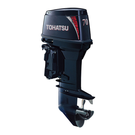
TOHATSU MFS60A User manual

SERVICE
M A N U A L
Supplement
SERVICE M A N U A L
5-4, Azusawa 3-Chome, Itabashi-Ku
Tokyo 174-0051, Japan
Tel: +81-3-3966-3117 Fax: +81-3-3966-0090
www.tohatsu.com
SERVICE
MANUAL
OB No.003-21073-0
1903NB
Printed in Japan
OB No.--|- NB
Supplement
Supplement
MFS A
STROKE
4 STROKE MFS 60A
MFS A
STROKE
SME_MFS60A_Cover_190326N.indd 1 2019/03/26 9:50

Copyright © 2019 Tohatsu Corporation. All rights reserved. No part of this manual
may be reproduced or transmitted in any form or by any means without the express
written permission of Tohatsu Corporation.
SME_MFS60A_Cover_190326N.indd 2 2019/03/26 9:50

Introduction
This manual has been prepared as a supplement for the MFS60A.
Please utilize this manual together with the service manual of our outboard motors MFS40A/MFS50A.
Contents
1. Service Information
1. Tools and Instruments .................. 1-2
1) Test Propeller .......................................... 1-2
2) Measuring instruments ............................ 1-2
2. Service Data
1. Specifications ............................. 2-2
2. Maintenance Data ....................... 2-6
3. Tightening Torque Data ............... 2-14
3. Maintenance
1. Inspection Schedule .................... 3-2
2. Inspection Items......................... 3-3
1) Inspection and Adjustment of
Valve Clearance ...................................... 3-3
2) Inspection of Idle Speed......................... 3-4
3) Inspection of Ignition Timing................... 3-4
4. Fuel System (Fuel Injection)
1. Piping Arrangement Diagram ......... 4-2
Fuel Hose, Vent Hose, Breather Hose,
Cooling Water Hose ...................................... 4-2
2. Ignition System ........................... 4-3
(1) Configuration of ECU System ........ 4-3
(2) Ignition Control........................... 4-4
1) Ignition Timing Controls.......................... 4-4
2) Ignition and Combustion Orders ............. 4-4
3) Ignition Timing ........................................ 4-4
4) Operations ............................................. 4-4
(3) Fuel Feed System......................... 4-5
5. Power Unit
1. Parts Layout ............................... 5-2
Engine .......................................................... 5-2
Magneto ....................................................... 5-3
Electric Parts................................................ 5-4
Fuel system .................................................. 5-6
Vapor Separator............................................ 5-8
Intake Manifold............................................ 5-10
Pulley • Timing Belt....................................... 5-12
Cylinder Head & Oil Pump............................ 5-13
Cylinder • Crankcase .................................... 5-15
Piston & Crankshaft ..................................... 5-16
Top Cowl...................................................... 5-17
2. Inspection Items ......................... 5-18
1) Inspection of Compression Pressure ..... 5-18
2) Inspection of Oil Pressure...................... 5-18
3) Inspection of Valve Clearance................ 5-18
4) Removing Power Unit............................. 5-18
5) Removing Timing Belt and Pulley............5-22
6) Inspection of Timing Belt .......................5-22
7) Installation of Pulley and Timing Belt ......5-23
8) Removing Cylinder Head........................5-24
9) Inspection of Valve Spring...................... 5-27
10) Inspection of Valve ................................5-28
11) Inspection of Valve Guide ......................5-28
12) Inspection of Valve Seat.........................5-29
13) Correction of Valve Seat........................5-30
14) Inspection of Rocker Arm and
Rocker Arm Shaft ..................................5-32
15) Inspection of Cam Shaft ........................5-33
16) Inspection of Cylinder Head ..................5-34
17) Inspection of Oil Pump ..........................5-35
18) Installation of Valves ..............................5-36
19) Installation of Cam Shaft........................ 5-37
20) Installation of Rocker Arm Shaft.............5-38
21) Installation of Oil Pump..........................5-38
22) Installation of Cylinder Head..................5-39
23) Disassembly of Cylinder Block................5-40
24) Removing of Drive Pulley.........................5-41
25) Installing of Drive Pulley...........................5-41
26) Inspection of Cylinder ............................5-41
27) Inspection of Piston Outer Diameter .....5-42
28) Inspection of Cylinder Inner Diameter ...5-42
29) Inspection of Piston Clearance..............5-42
30) Inspection of Piston Ring Side Clearance5-43
31) Inspection of Piston Rings .....................5-43
32) Inspection of Piston Pins .......................5-44
33) Inspection of Connecting Rod
Small End Inner Diameter ......................5-44
34) Inspection of Connecting Rod
Big End Side Clearance..........................5-44
35) Inspection of Crankshaft .......................5-45
36) Inspection of Crank Pin (rod journal)
Oil Clearance.........................................5-46
37) Inspection of Crank Shaft Main Journal
Oil Clearance......................................... 5-47
38) Selecting of Cylinder/Crankcase
Metal Bearing ........................................5-48
39) Selecting of Connecting Rod
Metal Bearing ........................................5-49
40) Assembling Piston and Connecting Rod .5-50
41) Installation of Power Unit .......................5-54

1
Service Information
1
1. Tools and Instruments................................................................................................ 1-2
1) Test Propeller .......................................................................................................................................... 1-2
2) Measuring instruments ............................................................................................................................ 1-2

1-2
Service Information
4st 60 2019
2) Measuring instruments
For the following measuring instruments, use commercially available ones.
Circuit tester ( Resistance : 1Ω, 10Ω, 10 kΩ, AC voltage : 30 to 300V, DC voltage : 30V )
Vernier calipers ( M1 type, 300 mm )
Micrometer ( minimum graduation of 0.01, outer, 0 to 25 mm, 25 to 50 mm, 50 to 75 mm )
Cylinder gauge ( 4 to 6 mm, 10 to 25 mm, 25 to 30 mm, 50 to 75 mm )
Ring gauge ( ø5.5, ø17, ø42, ø70 )
Dial gauge ( minimum graduation of 0.01 )
Thickness gauge ( 0.03 to 0.3 mm )
V block
Surface plate ( 500 mm x 500 mm )
Dial gauge magnet base or dial gauge stand
1. Tools and Instruments
1) Test Propeller
P/N. 3UR-64110-0
Outer diameter : 236 mm
Width : 22.5 mm
Outboard motor model Rotational speed at WOT
(Wide Open Throttle) (r/min)
MFS60A 5000 - 6000

2
2
Service Data
1. Specifications ........................................................................................................................ 2-2
2. Maintenance Data .................................................................................................................. 2-6
3. Tightening Torque Data .......................................................................................................... 2-14

2-2
Service Data
4st 60 2019
1. Specifications
Item Unit
Model
MFS60A
ET
(with Remote Control)
ET
(with Multi Tiller Handle)
Overall Length mm (in) with Remote Control : 783 (30.8) with Multi Tiller Handle : 1,382 (54.4)
Overall Width mm (in) 404 (15.9)
Overall Height
S mm (in) 1,257 (49.5)
L mm (in) 1,390 (57.4)
UL mm (in) 1,504 (59.2)
Transom Length
S mm (in) 405 (15.9)
L mm (in) 538 (21.2)
UL mm (in) 652 (25.7)
L kg (lb) 97 (214) 102 (225)
UL kg (lb) 100 (221) 105 (231)
Maximum Output kW (ps) TAC 44kW (60PS) / EU 44.1kW (60PS)
Full-throttle revolution
speed range
r/min 5,000 to 6,000
Full-throttle Fuel
Consumption L (gal.)/hr 17.8 (4.70)
Idling (Neutral [N]) r/min 650/750/850/950
Trolling (Forward [F]) r/min 650/750/850/950
Engine Type 4 stroke
No. of Cylinders 3
Piston Displacement cm³ (cui) 866 (52.8)
Valve System SOHC
Bore x Stroke mm (in) 70 x 75 (2.76 x 2.95)
Compression Ratio 10.5
Shift Operation
System
Remote
Control
Front Shift
(Manual)
Starting System Electric Start
Lubrication System Wet Sump
Cooling System Water Cooling (Impeller System)
Exhaust System Through-the-prop Exhaust
Ignition System Battery Ignition
Range of Ignition
Angle ATDC5° to BTDC20° (ECU timing control)
Spark Plugs IKR6G8 [NGK]
Alternator Output 12V−252W, 21A
Fuel Feed System Electronic Fuel Injection
Dimensions (approx.)
Weight (approx.)
Performance
Power Unit

2-3
2
4st 60 2019
Type of Fuel
Unleaded Gasoline (Research Octane Number 90 or over, Pump posted Octane Number 87 or over)
Fuel Tank Capacity L 25
Fuel Priming System
ECU (Electronic Control Unit)
Fuel Pumping System Mechanical (Plunger) pump + Electric System
Engine Oil
Type 4 Stroke Engine (Motor) Oil
Grade API SH, SJ, SL
SAE 10W-30, 10W-40
Quantity L 2.4 (when oil filter is replaced with new one)
Gear Oil
Type Hypoid Gear Oil
Grade *1 API GL-5
*1 SAE #80-90
Quantity cm³ (US qt) 500 (0.53)
Fuel & Oil
Gear Shift Positions F – N – R
Gear Ratio 2.08 (13 : 27)
Type of Gears
Spiral Bevel Gear
Clutch Dog Clutch
Propeller Shaft Driving
Spline
Propeller Rotation
Direction Clockwise at forward (F) shift as viewed from rear
Propeller (Standard) Marking 14P
Lower Unit
No. of Trim Steps Steps 4
Trim Angle (Transom 12)
*2 Degrees −4° to +16°
Shallow Water Drive
Angle (Transom 12) *2 Degrees Adjustable
Max. Tilt Angle *3 Degrees 62
Steering Angle *4 Degrees 35+35
Max. Allowable Transom
Thickness
mm (in) 31 to 70 (1.22 to 2.76)
Bracket
*1 Both API and SAE requirements shall be met.
*2 Angle relative to horizon when transom angle is 12 degrees.
*3 Tilting Range
*4 Full Steering Angle Range to Starboard and Port
Item Unit
Model
MFS60A
ET
(with Remote Control)
ET
(with Multi Tiller Handle)

2-4
Service Data
4st 60 2019
Over-revolution
Protection
Controls engine speed to approximately 6,200 r/min or
less (High Speed ESG). Warning buzzer sounds.
Engine Hydraulic
Pressure Low *1
Controls engine speed to approximately 2,800 r/min or
less (Low Speed ESG). Warning buzzer sounds, and warning lamp A is lit.
Engine Cooling Water
Temperature High.
Controls engine speed to approximately 2,800 r/min or
less (Low Speed ESG). Warning buzzer sounds, and warning lamp B is blink.
Engine Cooling Water
Temperature Abnormally High.
Controls engine speed to approximately 850 r/min (force Idling Speed). Warning buzzer
sounds, and all warning lamps are blink.
Each Engine Sensor
Malfunction *1
Controls engine speed to approximately 2,800 r/min or
more (Low Speed ESG). All warning lamps are blink.
Warning System
Operation Check Warning buzzers sounds for 1 second and lamp is lit for 1 second.
Warning System
*1 Stop engine to cancel warning system operation.
Item Unit
Model
MFS60A
ET
(with Remote Control)
ET
(with Multi Tiller Handle)

2-5
2
4st 60 2019

2-6
Service Data
4st 60 2019
2. Maintenance Data
Parts Name Item Standard Value
Engine Parts
Cylinder Head Build up of carbon in combustion chamber
Measure the cam journal clearance 42.000 to 42.025 mm (1.65354 to 1.65453 in)
Distortion or damage on mating surface Distortion Amount : 0.05 mm (0.0020 in) or less
Corrosion on the mating surface
Cooling water passage clogged
Cylinder Deposition in water jacket
Wear of bore : Use cylinder gauge to 70.00 mm (2.7559 in)
measure inner diameter.
Seizure, cylinder liner damage, or wear
Taper
Out-of-roundness
Distortion or damage on cylinder Distortion Amount : 0.05 mm (0.0020 in) or less
head mating surface
Engine Anode
Piston Outer Diameter 69.97 mm (2.7547 in)
Measure outer diameter at 12 mm (0.47 in)
above lower end of piston skirt
(at right angle to piston pin).
Piston Clearance 0.020 to 0.055 mm (0.00079 to 0.00217 in)
Carbon build up on piston crown
and in ring grooves
Scratch on the sliding surface
Measure side clearance between Top Ring : 0.04 to 0.08 mm (0.0016 to 0.0031 in)
piston ring and ring groove.
Second Ring : 0.01 to 0.05 mm (0.0004 to 0.0020 in)
Oil Ring : 0.03 to 0.13 mm (0.0012 to 0.0051 in)
Measure piston pin hole diameter. 17.005 mm (0.66949 in)
Clearance between piston pin and pin hole 0.002 to 0.012 mm (0.00008 to 0.00047 in)
Piston Pin Outer Diameter 17.000 mm (0.66929 in)
Piston Ring Ring End Note : Measurement of ring
end gap : If ring gauge
is not available, use
cylinder bore top or
bottom with small wear.
Ring Gage 70.000 mm (2.75591 in)
Gap
Top Ring Top Ring : 0.20 to 0.35 mm (0.0079 to 0.0138 in)
Second Ring Second Ring : 0.35 to 0.50 mm (0.0138 to 0.0197 in)
Oil Ring Oil Ring : 0.20 to 0.70 mm (0.0079 to 0.0276 in)
Connecting Rod Small End Inner Diameter 17.012 mm (0.66976 in)
Big End Oil Clearance 0.020 to 0.045 mm (0.00079 to 0.00177 in)
Big End Side Clearance 0.10 to 0.20 mm (0.0039 to 0.0079 in)
Crankshaft
Crankshaft runout : Use V blocks to
support crankshaft at journals of
both ends.
Less than 0.05 mm (0.0020 in) at both ends and at the center.
Crank pin outer diameter 37.99 mm (1.4957 in)
Main journal outer diameter 39.99 mm (1.5744 in)
Metal bearing oil clearance 0.020 to 0.041 mm (0.0008 to 0.0016 in)
Crankshaft side clearance 0.05 to 0.15 mm (0.0020 to 0.0059 in)

2-7
2
4st 60 2019
Functional Limit Action To Be taken
Clean to remove.
42.050 mm (1.65551 in) Replace if more than specified limit.
0.1 mm (0.004 in)
Correct. (Use water proof sand paper of #240 to 400 on the surface plate to level. Use #600 to finish.)
Correct if possible, or replace.
Clean to remove.
Clean to remove.
70.06 mm (2.7583 in) Replace if more than specified limit.
Replace if severely damaged on the piston sliding surface, which
cannot be repaired with sand paper of No. 400 to 600, or damaged
over specified limit.
0.08 mm (0.0031 in)
0.06 mm (0.0024 in)
0.1 mm (0.004 in) Correct. (Use water proof sand paper of #240 to 400 on the
surface plate to level. Use #600 to finish.)
Replace if severely consumed.
69.90 mm (2.7520 in) Replace if less than specified limit.
0.150 mm (0.00591 in) Replace if more than specified limit.
Clean to remove.
Correct if possible (with #400 to 600 water proof sand paper), or replace.
Top Ring : 0.10 mm (0.0039 in) Replace if more than specified limit.
Replace oil ring when top ring or second ring is replaced.
Second Ring : 0.07 mm (0.0028 in)
Oil Ring : 0.15 mm (0.0059 in)
17.012 mm (0.66976 in)
0.040 mm (0.00157 in) Replace if more than specified limit.
16.970 mm (0.66811 in) Replace if less than specified limit.
Top Ring : 0.55 mm (0.0217 in) Replace if the gap is over specified limit only if cylinder inner wear is
less than specified limit. Replace oil ring when top ring or second ring
is replaced.
Second Ring : 0.70 mm (0.0276 in)
Oil Ring : 1.00 mm (0.0394 in)
17.040 mm (0.6709 in) Replace if more than specified limit.
0.060 mm (0.00236 in) Replace if more than specified limit.
0.30 mm (0.0118 in) Replace if more than specified limit.
0.05 mm (0.0020 in) Replace if more than specified limit.
37.97 mm (1.4949 in) Replace if less than specified limit.
39.97 mm (1.5736 in) Replace if less than specified limit.
0.060 mm (0.00236 in) Replace if more than specified limit.
0.50 mm (0.0197 in) Replace if more than specified limit.

2-8
Service Data
4st 60 2019
Parts Name Item Standard Value
Engine Parts
Intake Valve Valve Clearance IN 0.20 to 0.25 mm (0.008 to 0.010 in)
Exhaust Valve EX 0.30 to 0.35 mm (0.012 to 0.014 in)
Valve Stem Outer Diameter IN 5.48 mm (0.2157 in)
EX 5.46 mm (0.2150 in)
Valve Guide Inner Diameter IN 5.51 mm (0.2169 in)
EX 5.51 mm (0.2169 in)
Clearance between valve guide
and valve stem
IN 0.008 to 0.040 mm (0.00031 to 0.00157 in)
EX 0.025 to 0.057 mm (0.00098 to 0.00224 in)
Width of contact with valve seat IN 1.4 mm (0.06 in)
EX 1.4 mm (0.06 in)
Valve Spring Free Length 38.7 mm (1.52 in)
Cam Shaft Cam Height (Both IN and EX) 35.70 mm (1.4055 in)
Journal Outer Diameter #1: 41.92 mm (1.6504 in)
#2/3/4: 41.95 mm (1.6516 in)
Clearance between cam shaft and holder
(journal area)
#1: 0.075 to 0.110 mm (0.00295 to 0.00433 in)
#2/3/4: 0.045 to 0.080 mm (0.00177 to 0.00315 in)
Rocker Arm & Rocker Arm Inner Diameter 18.01 mm (0.7091 in)
Shaft Shaft Outer Diameter 17.99 mm (0.7083 in)
Shaft Clearance 0.006 to 0.035 mm (0.00024 to 0.00138 in)
Timing Belt External Appearance
Engine Block
Compression Pressure (Reference) at 600 to 700r/min
1.5 MPa (218 psi) [15.3 kgf/cm2] ± 10%
Fuel and Lubrication Parts
Fuel Regulator Fuel Pressure Atmospheric Pressure + 0.29 MPa (43 psi) [3.0 kg/cm2] ± 10%
Vapor Separator Seal Ring Wear and Damage
Float Height Float Height : 44 to 50 mm (1.732 to 1.969 in)
Float Valve Float Drop (Reference) : 30.0 mm (1.181 in)
Oil Pump Pump Body Inner Diameter −
Clearance between Outer Rotor and Body −
Height of Outer Rotor −
Clearance between sides of rotor and body −
Clearance between outer and inner rotors −

2-9
2
4st 60 2019
Functional Limit Action To Be taken
Adjust into specified range.
5.46 mm (0.2150 in) Replace if less than specified limit.
5.44 mm (0.2142 in)
5.55 mm (0.2185 in) Replace if more than specified limit.
5.57 mm (0.2193 in)
0.070 mm (0.00276 in) Replace if more than specified limit.
0.100 mm (0.00394 in)
2.0 mm (0.08 in) Replace if more than specified limit.
2.0 mm (0.08 in)
37.1 mm (1.46 in) Replace if less than specified limit.
35.34 mm (1.3913 in) Replace if less than specified limit.
#1: 41.89 mm (1.6492 in) Replace if less than specified limit.
#2/3/4: 41.92 mm (1.6504 in)
#1: 0.150 mm (0.0059 in) Replace if more than specified limit.
#2/3/4: 0.120 mm (0.0047 in)
18.05 mm (0.7106 in) Replace if more than specified limit.
17.94 mm (0.7063 in) Replace if less than specified limit.
0.090 mm (0.00354 in) Replace if more than specified limit.
Wear, Damage, Elongation Replace if necessary.
Check if rotating parts, sliding parts and sealing parts cause compression leakage.
Replace if out of specified range.
Wear, Damage, Deterioration Due To Gasoline
Replace if necessary.
Replace if out of specified range.
Wear, Deterioration, Damage Replace if necessary.
40.8 mm (1.606 in) Replace if more than specified limit.
0.25 mm (0.0098 in) Replace if more than specified limit.
14.96 mm (0.5890 in) Replace if less than specified limit.
0.11 mm (0.0043 in)
(Including oil pump cover wear)
Replace if more than specified limit.
0.16 mm (0.0063 in) Replace if more than specified limit.

2-10
Service Data
4st 60 2019
Parts Name Item Standard Value
Electric Parts
Magneto Ignition Timing (at 850 r/min) ATDC 5°±5°
Spark Performance (at 500 r/min) 10 mm (0.4 in) or over
(Use genuine spark tester.)
Alternator Output (at 4,000 r/min) 12 V 252 W
Alternator Resistance
Between Yellow and Yellow (at 20°C)
0.28 to 0.42Ω
Crank Position Sensor (CPS,
Pulser Coil)
Resistance Between Terminals
Between Red/White and Black (at 20°C)
148 to 222Ω
Encoder Ring (Flywheel) Clearance 0.7 to 0.9 mm (0.028 to 0.035 in)
Ignition Coil Primary Coil Resistance
Between Black/White and Black (at 20°C)
2.72 to 3.68 Ω
Secondary Coil Resistance
(Between High Tension Cable and Black) (at 20°C)
15.6 to 23.4 kΩ
[KΩRange]
Between Plug Cap and Black
19.4 to 29.6 kΩ
Plug Cap Resistance Between Terminals [kΩRange] 3.0 to 7.0 kΩ
Spark Plugs Plug Type IKR6G8 (NGK)
Spark Gap 0.7 to 0.8 mm (0.028 to 0.032 in)
Fuel Injector Resistance Between Terminals 11.40 to 12.66Ω
Throttle Position Sensor
Resistance Between Terminals[kΩRange]
Between Blue and Black
Less than 5 kΩ
ISC Valve Resistance Between Terminals 27 to 33Ω "Refer to 8-24 page"
MAT (Manifold Temperature)
Resistance Between Terminals[kΩRange]
(at 25°C) 1.8 to 2.2 kΩ
Sensor
Engine Temperature Sensor
Resistance Between Terminals[kΩRange]
(at 5°C) 4.24 to 4.86 kΩ
(at 25°C) 1.90 to 2.10 kΩ
(at 100°C) 0.166 to 0.204 kΩ
Rectifier Resistance Between Terminals "Refer to 8-34 page"
Starter Motor Battery 12 V-100 AH to 12 V-120 AH
Output 12 V 1.4 kW
Clutch Overrunning Clutch
Brush Length 16.0 mm (0.63 in)
Commutator Undercut 0.5 to 0.8 mm (0.020 to 0.032 in)
Commutator Outer Diameter 29.0 mm (1.142 in)
Fuse Capacity 20 A x 2, 30 A x 1

2-11
2
4st 60 2019
Functional Limit Action To Be taken
10 mm (0.4 in) Replace if less than specified value.
Replace if out of specified range.
Adjust to specified range.
Replace if out of specified range.
Clean to remove carbon build up and dirt. Adjust with side electrode.
Replace if electrodes are severely worn.
1.0 mm (0.039 in)
Replace if out of specified range.
Replace throttle body ass'y if out of specified range.
Replace if out of specified range.
12.0 mm (0.472 in) Replace if less than specified value.
0.2 mm (0.008 in) Replace if less than specified value.
28.0 mm (1.102 in) Replace if less than specified value.
Burn out

2-12
Service Data
4st 60 2019
Parts Name Item Standard Value
Coolong System Parts
Thermostat Valve Operation Starting Temperature (Submerged) 60°C ± 1.5°C (140 ± 3°F)
Valve Full Open Temperature (Submerged) 75°C (167°F)
Valve Full Open Lift (Submerged) 3.0 mm (0.12 in) or more
Pump Impeller Wear, Crack
Pump Case (Liner) Wear
Guide Plate Wear
Lower Unit Parts
Anode Gear Case Anode Consumption
Clutch Spring Free Length 66 to 70 mm (2.60 to 2.76 in)
Propeller Shaft Bearing Wear and Damage
Oil Seal Wear
Propeller Shaft Runout
Bevel Gears Pinion Gear (B Gear) Height 0.60 to 0.64 mm (0.0236 to 0.0252 in)
Backrush between forward gear and pinion (A and B gears)
"Refer to Chapter 6."
0.31 to 0.62 mm (0.0122 to 0.0244 in)
Reverse Gear (C Gear) Washer Thickness 3.0 mm (0.118 in)
Propeller Wear, Bend, Crack, Break
Drive Shaft Spline (Upper) Base Tangent Length, 3 Gears 7.9 mm (0.311 in)
Bearing Damage
Oil Seal Wear and Damage
Drive Shaft Runout
Power Tilt Parts
Oil Pump Type Gear Pump
Oil Capacity 325 cm3(11.0 fl.oz.)
Recommended Oil ATF (DEXRON ǿǿǿ)
PTT Motor Voltage DC 12V
Continuous Run 60 seconds or less
Output 250 W
Direction of Revolution Forward, Reverse
Circuit Breaker
Type Bimetal
ON/Reset Time
40 sec or more (36 A)/30 sec or less [25°C (77°F)]
Brush Length 9.75 mm (0.384 in)
Commutator Outer Diameter 22.0 mm (0.866 in)
Depth of Undercut 1.8 mm (0.071 in)
Tilt Cylinder Piston Diameter 32.0 mm (1.260 in)
Tilt Rod Diameter 16.0 mm (0.630 in)
Stroke 101.0 mm (3.976 in)
PTT Switch Paddle Rocker Switch (3A)
Toggle Switch (20A)
Other
Parts
Oil Seals Damage, Wear

2-13
2
4st 60 2019
Functional Limit Action To Be taken
Any opening under ambient temperature
Replace if out of specified range.
75°C (167°F) because thermostat operation is delayed.
Measure valve open lift after 5 minutes.
3.0 mm (0.12 in)
Replace if less than specified limit.
Wear, crack or damage on tips and upper and lower surface lips Replace pump case liner and guide plate as a set.
Replace if severely worn
Replace if necessary.
0.4 mm (0.015 in) Replace if more than specified limit.
0.05 mm (0.0020 in) Replace if more than specified limit.
0.60 to 0.64 mm (0.0236 to 0.0252 in) Adjust, or replace.
Adjust, or replace.
2.85 mm (0.112 in)
Replace if less than specified limit.
Severe Damage
Replace if out of specified range
7.5 mm (0.295 in)
Replace if less than specified limit.
Replace if necessary.
0.4 mm (0.015 in) Replace if necessary.
0.5 mm (0.020 in) Replace if more than specified limit.
5.0 mm (0.236 in)
Replace if less than specified limit.
20.4 mm (0.803 in)
Replace if less than specified limit.
1.0 mm (0.039 in)
Replace if less than specified limit.
Lip deteriorated, degraded or damaged, or tightening margin
reduced to 0.5 mm (0.020 in) due to wear
Replace if out of specified range.

2-14
Service Data
4st 60 2019
3. Tightening Torque Data
Fastened Components
Wrench A
Screw B x Pitch
Type of
Fastener
Tightening Torque N•m
N•m lb•ft kg•m
Engine
Cylinder Head
(Cylinder Block and Cylinder Head)
14 M10 x 1.25 Bolt
1First Tightening Torque :
30 22 3
2Final Tightening Torque :
60 44 6
12 M8 x 1.25 Bolt
1First Tightening Torque :
15 11 1.5
2Final Tightening Torque :
30 22 3
Spark Plug 16 M12 x 1.25 Special 18 13 1.8
Tappet Lock Nut 10 M6 x 0.75 Nut 7 5 0.7
Rocker Shaft 12 M8 x 1.25 Bolt
1First Tightening Torque :
15 11 1.5
2Final Tightening Torque :
30 22 3
Thrust Bolt 10 M6 x 1.0 Bolt 9 7 0.9
Anode Plug 10 M16 x 1.5 Special 18 13 1.8
Anode — M5 x 0.8 Screw 2 1.4 0.2
Oil Filter Bolt — M20 x 1.5 Special 30 22 3
Oil Pump 10 M6 x 1.0 Bolt 8 6 0.8
Oil Filter — M20 x 1.5 Special
Tighten to 3/4 turn from temporary (270º)
18 13 1.8
Crankcase
(Cylinder Block to Crankcase)
12 M8 x 1.25 Bolt
1First Tightening Torque :
12 9 1.2
2Final Tightening Torque :
24 18 2.4
10 M6 x 1.0 Bolt
1First Tightening Torque :
6 4.5 0.6
2Final Tightening Torque :
11.5 8.5 1.15
Connecting Rod 10 M8 x 0.75 Bolt
1First Tightening Torque :
15 11 1.5
2Final Tightening Torque :
30 22 3
Flywheel 30 M20 x 1.25 Bolt 150 110 15
Timing Pulley 50 M39 x 1.5 Bolt 120 88 12
Cam Shaft Pulley 17 M10 x 1.25 Bolt 27 20 2.7
Oil Pressure Switch — PT1/8 Special 8 6 0.8
Power Unit 13 M8 x 1.25 Bolt
1First Tightening Torque :
15 11 1.5
2Final Tightening Torque :
30 22 3
Clamp Bracket 24
7/8-14UNF-2A
Nylon Nut 24 18 2.4
PTT Manual Valve — M12 Special 1.8 1.4 0.18
Drive Shaft Housing Engine Base
Rubber Mount Upper
(Center only)
13 M8 x 1.25 Bolt
1First Tightening Torque :
15 11 1.5
2Final Tightening Torque :
30 22 3
Engine Base
Main Body
(Exhaust passage side)
13 M8 x 1.25 Bolt
1First Tightening Torque :
15 11 1.5
2Final Tightening Torque :
30 22 3
Engine Base
Main Body (Rear 2 part) 13 M8 x 1.25 Bolt
1First Tightening Torque :
15 11 1.5
2Final Tightening Torque :
30 22 3
Oil Drain 16 M14 x 1.5 Bolt 24 18 2.4
Rubber Mount (Upper) 14 M10 x 1.25 Bolt, Nut 27 20 2.7
Rubber Mount (Lower) 17 M12 x 1.25 −−− 40 29 4
Table of contents
Other TOHATSU Outboard Motor manuals

TOHATSU
TOHATSU BFT 250A User manual

TOHATSU
TOHATSU MFS 6A3Z 8A3 9.8A3 User manual

TOHATSU
TOHATSU MFS 4 User manual

TOHATSU
TOHATSU M 4C User manual

TOHATSU
TOHATSU BFT 200D User manual

TOHATSU
TOHATSU 115 User manual

TOHATSU
TOHATSU MFS 30B User manual

TOHATSU
TOHATSU M 4C User manual

TOHATSU
TOHATSU MFS 40A User manual

TOHATSU
TOHATSU 2 Stroke 40C User guide

TOHATSU
TOHATSU MFS 30B User manual

TOHATSU
TOHATSU MFS 25C User manual

TOHATSU
TOHATSU MFS 6A3Z 8A3 9.8A3 User manual

TOHATSU
TOHATSU 9.9 User manual

TOHATSU
TOHATSU M 6B User manual

TOHATSU
TOHATSU MFS 3.5C User manual

TOHATSU
TOHATSU MFS 4C User manual

TOHATSU
TOHATSU M 4C User manual

TOHATSU
TOHATSU MFS 6A3Z User manual

TOHATSU
TOHATSU MFS 9.9E User manual