Tokyo Hy-Power HC-1500AT User manual
HC-1500AT
0
Instruction Manual
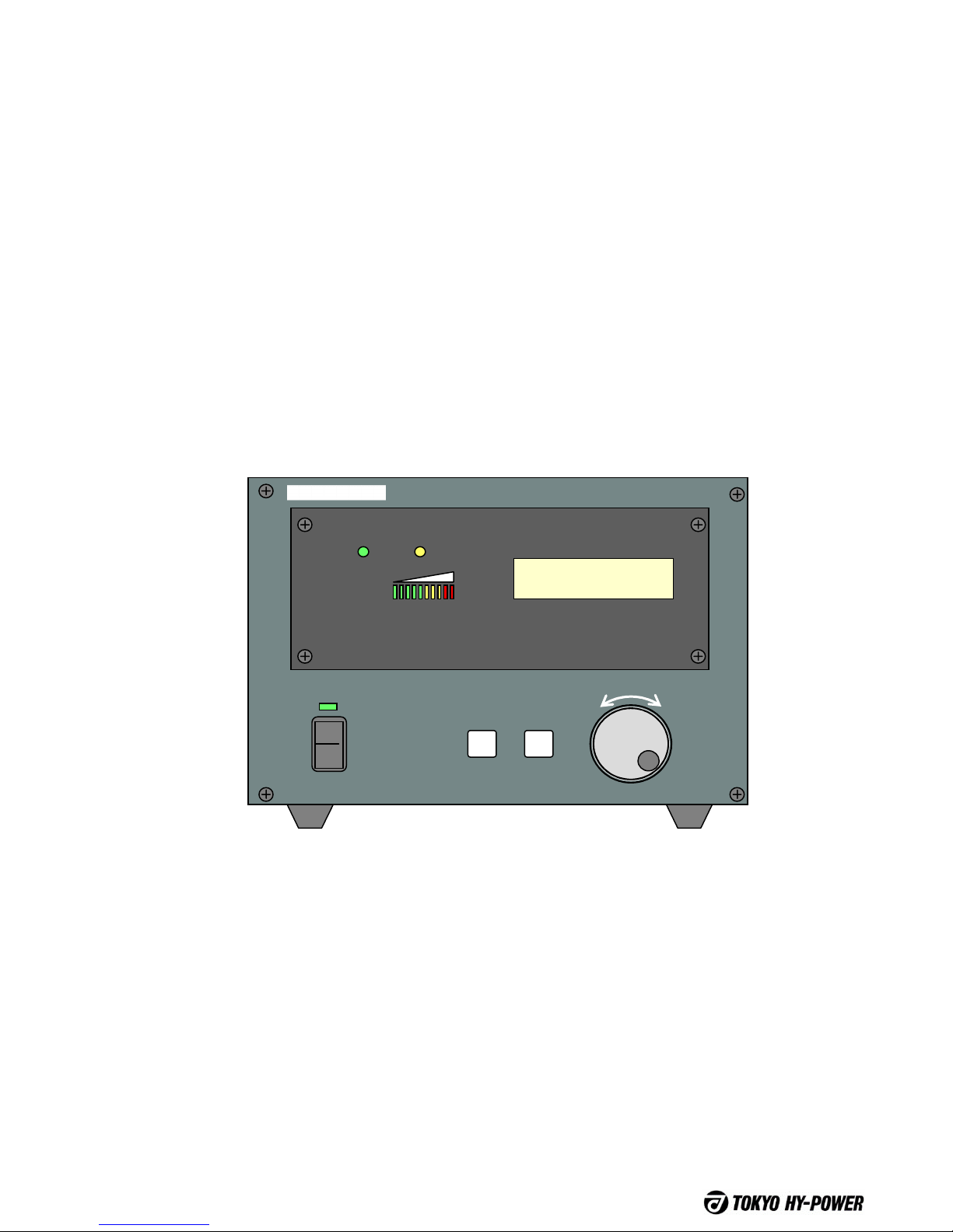
HF/50MHz Automatic Antenna Tuner
Model HC-1500AT
READY WARNING
SWR
1.5 2.0 3.0
HF AUTOMATIC ANTENNA TUNER HC-1500AT
SELECT
ENTRY
FUNCTION
POWER
OFF

HC-1500AT
1
Thank you for purchasing Tokyo Hy-Power model HC-1500AT, automatic antenna tuner.
HC-1500AT is a compact HF/50MHz band high power auto antenna tuner with a maximum
power handling capability of 1.5kW. The tuner fully intergrates with Tokyo Hy-Power Linear
amps such as HL-1.5KFX, HL-2.5KFX, HL-2500FX etc.
It is also designed to work with other linear amplifiers as well, due to the newly THP developed
band decoding technology. It boasts of an extremely fast tuning speed of 1 sec. max. in most
cases. When the transmitter is keyed, the tuner detects the antenna impedance (resistance
and reactance) directly, and the two variable capacitors are auto-adjusted so that tuner
matches the antenna impedance.
2. Features
1. Forward
• High speed and precision tuning due to the high resolution stepping motors driven by the
microprocessor: The typical tuning time is less than one second, with the exception on the
160m band. On this band, the typical tuning time is 3sec.
• Simple operation: Auto tunes even with ssb/voice as well as keyed codes.
During the auto-tuning time period the linear amp is held at STBY (stand-by), and then
automatically switches to OPER. (operate) as soon as the tuning is completed.
• Tuning position data is stored in the memory with respects to frequency, band segment and
antenna port. As a result re-tuning is extremely fast, When tuning up and
down the bands.
• With the newly developed band decoder, HC-1500AT is compatible with frequency band
information sent from such radio’s as ICOM, YAESU and KENWOOD, and can follow the
radio as you move within the band.
Furthermore the tuner can select the operating band independently through the built-in
frequency counter.
• The tuner is equipped with two data ports of IN and OUT for a series expandable serial
interface. With this feature, the band data from the transceiver can be transferred to the
linear amp by way of the tuner.

HC-1500AT
2
3. Cautions
Note the followings for the safety of the operator.
A If any smoke, odor, or fire is detected, take the following steps for safety.
1 Cease the transmission.
2 Turn off the power of linear amp and radio.
3 Turn off the power of tuner.
B High RF Voltage
A high RF Voltage is generated during the transmission period.
· Never remove the top cover.
· Never operate without connecting an antenna.
· Never touch RF connectors.
· Be careful of the tuner cabinet as it may bear RF voltage depending on the antenna type
connected.
· Those operators with heart pacemakers must not approach the tuner.
· Avoid the risk of RF burn from a high SWR antenna on its element length.
· Never touch cooling fan inside as well as L, C components, as they generate much heat
during operation.
C Limited Application
This tuner is designed for the use of the amateur radio station operated by qualified
operator. Application for other than designed purpose leads to the failure of the device
and/or the severe damage to the surrounding devices. Never exceed the maximum
handling power of 1.5kW.
D Setting
Internal parts such as tuning coils and motors are forced air cooled and need air
ventilations. Keep at least a few inches of space from the rear wall, and a space of rubber
feet height at the bottom. Keep out of direct sun light, in a clean dry environment.
E Power Derating for high SWR Antenna
When the antenna has high SWR of 3 to 4, reduce RF output power by at least a half not
to damage the tuning components.
Also never attempt to tune to very high SWR antenna, even if the tuner happens to work,
or the tuning relays and capacitors as well as coax cable will be severely heated and
damaged.
F Power ON Sequence
It is recommended to turn on the transceiver first, then the amplifier, and finally the auto
tuner.
G Power Off/Thru
When the POWER switch is turned off, ANT1 port is the default bypass antenna port.
H Tube Linear Amp
Combination with tube type linear makes plate tuning circuit and tuner network connected
in a cascade way. As they mutually affect each other, note the following tuning procedure.
1 Tune the amp with 50Ωdummy load first. Then, tune the tuner with linear amp in
STBY (off) mode.
2 Alternatively turn the tuner, first, with amplifier in STBY (off), and then tune the linear for
maximum power output.

HC-1500AT
3
4-1. Equipment Needed for an Operation
A. DC Power Supply
DC12V (11 – 14V), 2A (negative ground)
B. Coax Cable
RG8U or higher grade is recommended. RG8X and similar small diameter coax is not
recommended.
C. Transceiver
HF/50MHz radio that delivers at least 50W of output power, that drivers the tuner directly
when tuning. The radio with output power reduction feature is preferred when there is high
reflected power.
D. Linear Amp
The Linear amp of 1 to 1.5kW output with ALC feedback is preferred. Avoid the one with
over-shoot/ spiking.
E. Antenna
Antenna should have power handling capacity of 1,500W or more, and relatively low SWR.
Even if the high SWR is lowered with the tuner, it will make the coax cables heated, and
cause interferences around the vicinity.
F. Band Cable
Band cables for the respective radios are available as optional parts for the smooth and
comfortable operation. Please note that full break-in CW is not available when the band data
cable is not used.
(See 11, Connection/ Operation. Page 14 – 19.)
G. ISO Screw Bolts
This tuner uses ISO std. screws.

HC-1500AT
4
4-2. Specifications
Model HC-1500AT Specifications
Parameter Description Remarks
Frequency Range 1.8-50 MHz, all WARC bands included
Output Impedance Range 12.5 – 200 Ω(SWR=4.0)
(*16.6 – 150 Ω, SWR=3.0) * Reduced range on 1.8,
and 50 MHz.
Maximum-Handling Power 1.5 kW (P.E.P./CW), 1 kW on 50 MHz RTTY 1 kW recommended
Input Impedance 50 Ω
Tuning Power 10W min.
Tuning Time 1 sec. (typ.)
2.5 sec. (max.) Under typical worst SWR
condition on 1.8 MHz
DC-Power Voltage DC 12V – 14V
(5 mm φDC jack) From external DC power
supply (Power supply not
included.).
Current Drain 1.5 A max.
Quiescent Current 0.7 A
DC Power Polarity Negative ground
Display LCD Module Character display
Operating Temp. Range 0 deg. to +40 deg. C
VSWR (Max.) 1.5 (typ.) or lower After tuning
Circuit Type T-shaped circuit
Driving Motors Stepping Motors for Two Air Variable Capacitors 0.25 deg. resolution/step
L Changes Relays to short
Matching Algorithm Analog Control with MPU Phase and [Z] Magnitude
Detected
Tuning Memory 93 x 3 ch. max. For three ANT ports and
respective bands in total.
Dimension 200 x 140 x 300 mm (W x H x D) Approx. 8 x 5.6 x 12 inches
Weight Approx. 6.3 kg or 14.4 lbs.
Input Connector SO-239 (UHF)
Output Connectors Three SO -239’s
Cooling Partial air forced cooling fan
Accessories DC power cable with 5.5 mm dia. plug (4 feet)
Band control cable with DIN 7 pin plugs
(THP interface cable) To connect the THP amps.
ALC/PTT Out cable with RCA plugs To connect to amps.
Fuse DC 2A, 2 pcs.

HC-1500AT
5
READY WARNING
SWR
1.5 2.0
HF AUTOMATIC ANTENNA TUNER HC-1500AT
SELECT
ENTRY
FUNCTION
POWER
OFF
5. Explanations of Front and Rear Panels
1 2 3 4
5 6 7 8
(1)POWER
Switch to turn power on and off.
When turned off, the tuner is bypassed, RF is looped from the input through the output antenna ports.
(2)FUNCTION
Function button to access the operation menu. Used to set the various parameters and to operate
the tuner in manual mode.
(3)ENTRY
Button to select manual operation and its parameter settings.
(4)SELECT
The dial for selecting various parameters as well as changing tuning elements of the tuner.
By pressing the dial knob, you can shift to other parameter settings.
(5)Ready
Green lamp lights when tuning has successfully completed.
(6)WARNING
Yellow lamp blinks when tuning capacitor positions enter a critical and/or dangerous region. (high
amperage)
(7)SWR
LED bar graph displays SWR status of the tuner, SWR of 1.0 to 3.0 is signed with 10 pcs of LED
lamps. SWR of 1 is shown, when the tuner has tuned properly.
(8)LCD (Display)
Panel to display the various parameters of operation.
< FRONT PANEL >
HC-1500AT
6
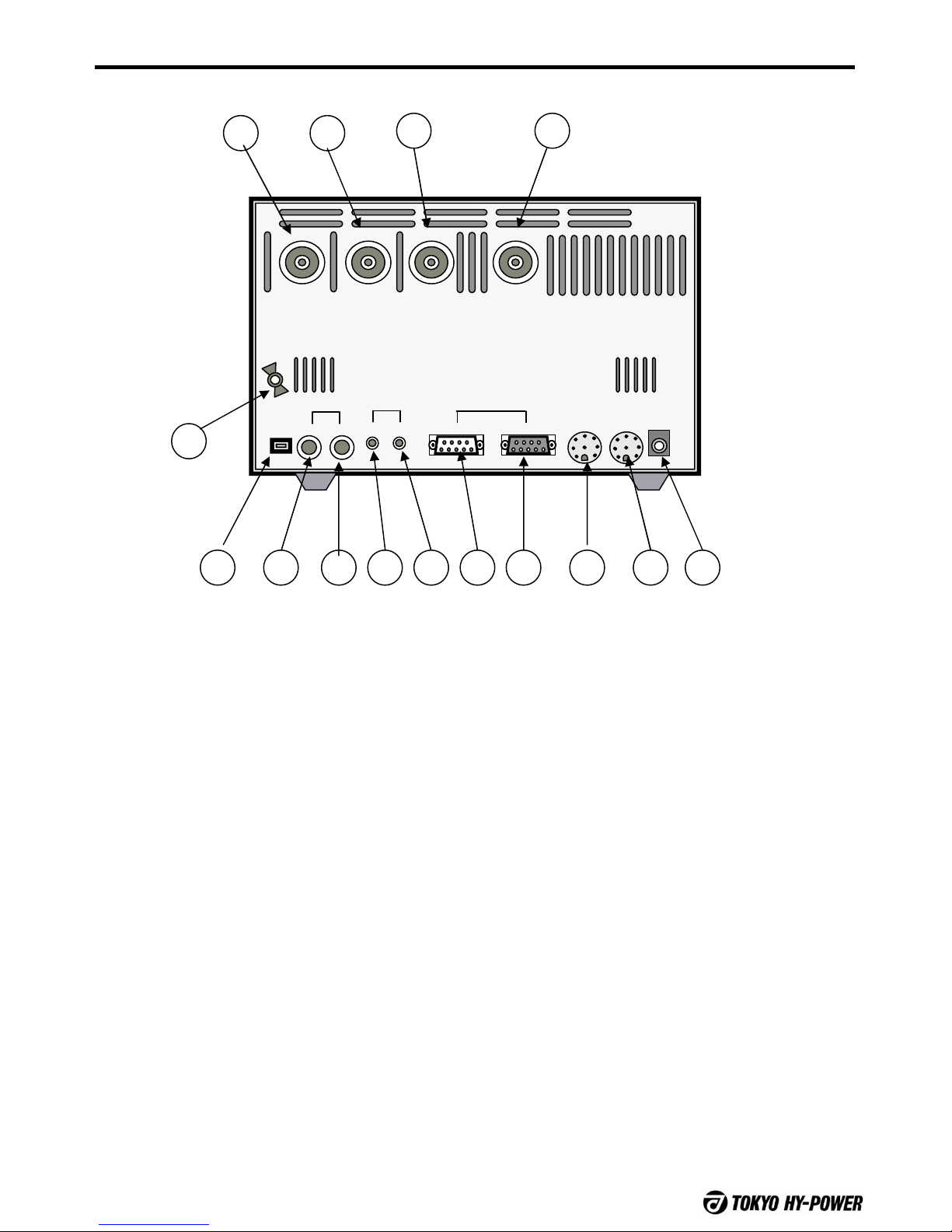
< REAR PANEL >
ANT 3 ANT 2 ANT 1
CONTYAESU
KENWOOD
I N
TRX
OUT
CIV
STBY
I NOUT
I N
OUT DC12V
USB
1 2 3 4
5
6 7 8 9 10 1211 13 14 15
(1)ANT3 Antenna Connector 3 (SO-239)
To be selected by Select rotary dial and
Entry button.
(2)ANT2 Antenna Connector 2 (SO-239)
To be selected by Select dial and Entry.
(3)ANT1 Antenna Connector 1 (SO-239)
Tuner network is usually connected to this
connector, if not selected in particular.
(4)TRX IN Connecter (SO-239)
Connect a coax cable from ANT (antenna)
connector of the linear amplifier.
(5)GND
Ground terminal.
(6)USB
Serial interface USB socket for the future
firmware version up-grade.
(7)STBY-OUT
RCA jack to connect PTT cable to SEND
(or STBY, REMOTE) socket of the linear amp.
(8) STBY-IN
RCA jack to connect PTT cable form SEND
(or TX GND, REMOTE, RELAY etc.) socket
of transceiver.
(9) CIV-OUT
Output socket for ICOM radio’s CI-V interface.
(10) CIV-IN
Input socket for ICOM radio’s CI-V interface.
(11) KENWOOD-OUT
Output connector socket for KENWOOD
radio’s control interface.
(12) KENWOOD-IN
Input connector for KENWOOD radio’s
control interface.
(13) YAESU
Socket for YAESU radio ‘s band data cable.
(14) CONT (THP Interface)
Socket for interface cable of Tokyo Hy-
Power’s original tuner connection specs.
Compatible with HL-1.5KFX, HL-2.5KFX and
HL-2500FX.

HC-1500AT
7
6. Explanation of LCD Display
1.8MHz STBY NON
C1=12 C2=19 ANT1
Typical Tuner Annunciations
LCD displays status and parameters of all tuner operations. Display capacity is 16 characters
by 2 rows.
Band
Shows the present
band selected.
Example
KEN/CIV mode
1.8MHz
24MHz etc.
THP/YAE/NON
mode
1.82Mz
24MHz etc.
FRQ mode
1.825
24.905 etc.
States
Shows the present
status of the tuner.
Example
STBY: Stand by
TRCK: Tracking
RADY: Tuned
TUNE: Tuning
WAIT: Presetting
FANC: Set mode
TXCW: Waiting for
carrier
CUNT: Counting
THRU: Through
FAIL: No carrier
NOCT: Count failure
Interface
Shows the type of
band decode method.
Example
NON: Manual band
select
CIV: ICOMCI-V
YAE: YAESU
KEN: KENWOOD
THP: THP
FRQ: Freq. Count
method
C1 Position C2 Position Antenna
Shows selected
antenna type
under tuner
network ON.
and/or OFF
(through).
Example
C1=00 – 99 Example
C1=00 – 99 Example
Network ON
ANT1
ANT2
ANT3
Network OFF
(through)
THU1 (to ANT 1)
THU2 (to ANT 2)
THU3 (to ANT 3)
Example of
LCD Sign
TOKYO HY-POWER
HC-1500AT Verx.xx
Other
Annunciations
1.82Mz
C1=12 C2
Pointer
Appears at the top of
corresponding
parameter.
Initial message
TUNE ERROR!!
Push FUNC _restat
Error message
Pointer waiting
for freq. band
change
command
HC-1500AT
8
7-1. Special Notes
B. Antenna Setting
Any antenna port can be programmed for a particular band.
Once programmed, the data remains in memory until it is re-programmed.
C. Band Data
As a means of band data transfer, following interfaces are available for HC-1500AT.
·CIV: ICOM’s CI-V interface. As 1 KHz order data is carried, band data is transferred
instantaneously making quick QSY’s possible
·KEN: KENWOOD’s interface of EIA-232C serial. Also handles detailed data.
·YAE: YAESU’s 4 bit band data. Since only the band data is carried it needs a supplementary
freq. data for low bands.
·THP: The mode to connect to TUNER terminal of THP linear amps. (PWM hand-shake.)
·FRQ: Frequency measuring mode through the built-in frequency counter. Needs one push of
button to start up.
·NON: NON interface. Completely manual setting mode.
A. For Amateur Service
HC-1500 is strictly for amateur radio use only.
Operation outside the amateur bands operation is not recommended and could
will cause the tuner to malfunction.
Please read following notes before you power up the tuner.

HC-1500AT
9
D. Recommended Interface
Linear
TRX HL-2500FX HL-2.5KFX HL-1.5KFX Others
ICOM · From x-ceiver to HC-1500AT, through CI-V,
from HC-1500AT to linear, through CI-V.
(See 16 page.)
· From x-ceiver to HC-
1500AT through CI-V.
Linear is manually set.
YAESU · From x-ceiver to linear, through YAE, from
linear to HC-1500AT, through THP/(TUNER)
(See 18 page)
· From x-ceiver to HC-
1500AT through YAE.
Linear is manually set.
KENWOOD · From x-ceiver to HC-1500AT, through KEN,
from HC-1500AT to linear, through KEN.
(See 19 page)
· From x-ceiver to HC-
1500AT through KEN.
Linear is manually set.
ELECTRAFT
K3 · From x-ceiver to linear, through ELC, from
linear to HC-1500AT, through THP. · From x-ceiver to HC-
1500AT through YAE.
Linear is manually set.
Others Both linear and
HC-1500AT
through Freq.
Count method
(See 15 page)
Linear to be manually set.
HC-1500AT per Freq.
Count method
(See 15 page)
There are various interface combinations for the transceiver and linear amp that can be
connected to HC-1500AT. The following are typical combinations.
(YAE: YAESU interface, KEN: KENWOOD interface, THP: Tokyo Hy-Power interface)
HC-1500AT
10
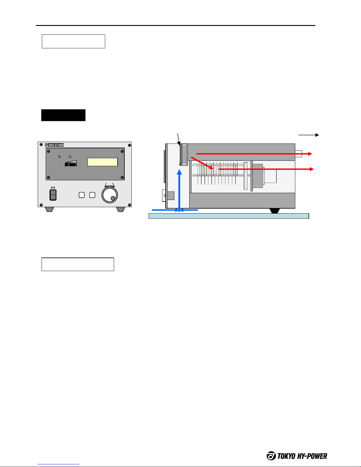
7-2. Setting and Cooling Fan Air Flow
Air flow
Direction
READY WARNING
SWR
1.5 2.0
HF AUTOMATIC ANTENNA TUNER HC-1500AT
SELECT
ENTRYFUNCTION
POWER
OFF
FAN Side view
This tuner is cooled with a forced air cooling fan. Never block the vent hole of the rear
panel. Allow two inches rear clearance. Chassis bottom must be above and free from
desk by rubber feet height.
Fan Start Condition
Air Flow
Cooling fan is thermally controlled and turns on when the ambient temperature rises to
30 ˚C. At temperature below 30C the fan is not operational.
HC-1500AT
11
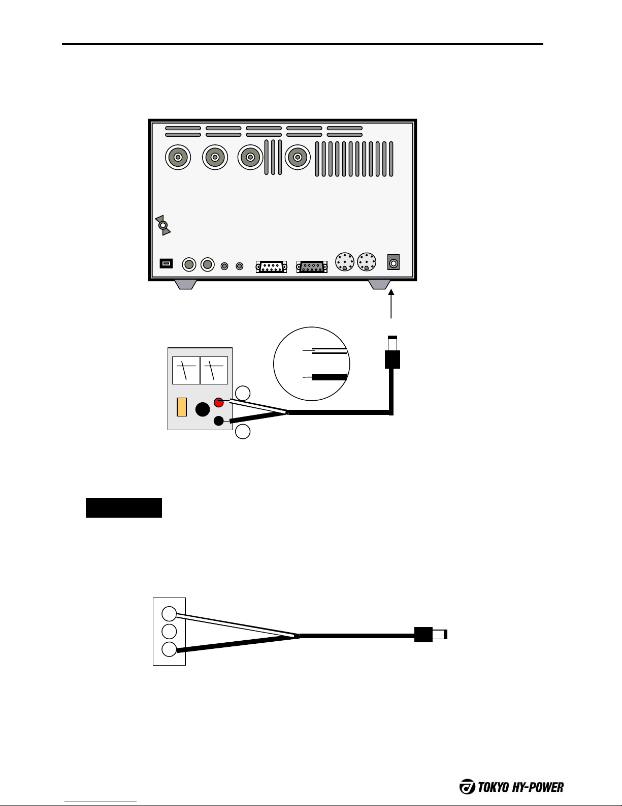
8. DC Power Supply
ANT 3 ANT 2 ANT 1
CONTYAESU
KENWOOD
I N
TRX
OUT
CIV
STBY
I N
OUT
I NOUT DC12V
External DC power supply of DC 12V, is required.
Connect supplied DC power cord to “DC 12V” socket at the rear panel of the tuner.
Supplied DC cord
12V1.5A
+
-
+
--
1
2
3
THP HL-2500FX has DC power outlet (12V, 2A) at the rear panel.
You may connect tuner’s DC power cord to this socket of 12V/2A.
SMR-03V DC Plug
HL2500FX DC OUT
(12V/2A) To DC12V
Note
White lead of included DC cord is for positive.
HC-1500AT
12
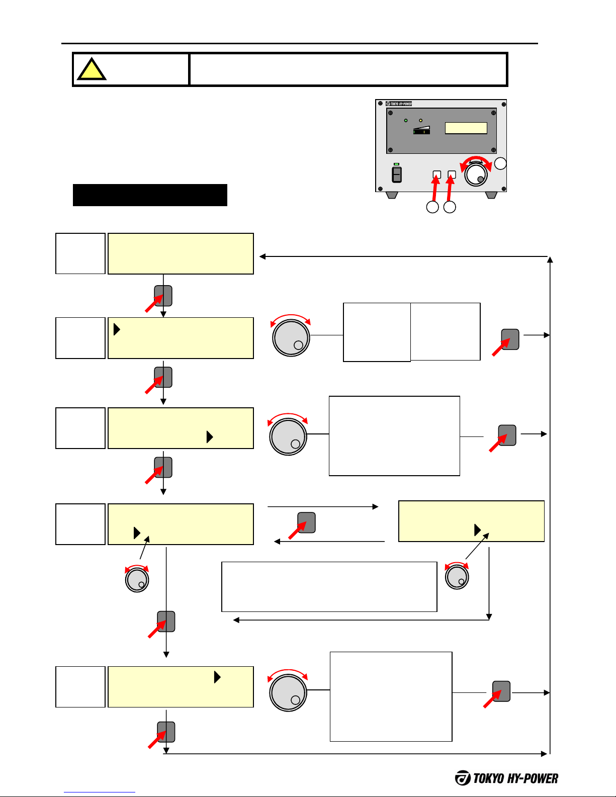
9. Function Menu List
To make a band change, antenna port selection, interface
setting etc. you can set the parameters by pressing
(1) FUNC button, (2) rotating the SELECT dial, and
pressing (3) ENTRY button.
CAUTION:
!Never transmit while setting the following functions.
1.8MHz FUNC NON
C1=12 C2=19 ANT1
1.8MHz FUNC NON
C1=12 C2=19 ANT1
1.8MHz FUNC NON
C1 12 C2=19 ANT1
1.8MHz FUNC NON
C1=12 C2=19 ANT1
1.8MHz STBY NON
C1=12 C2=19 ANT1
1.8MHz FUNC NON
C1=12 C2 19 ANT1
FUNCTION SELECT
FUNCTION
FUNCTION
FUNCTION
FUNCTION
SELECT
ENTRY
ENTRY
SELECT Interface Setting
NON: Manual Band Change
CIV: ICOM CI-V
YAE: YAESU Band Data
KEN: KENWOOD Band
Data
THP: THP Original Interface
FRQ: Freq. Count Method
Antenna/Thru Select
ANT 1: Network ON, to ANT 1
ANT 2: Network ON, to ANT 2
ANT 3: Network ON, to ANT 3
THU 1: Network OFF, to ANT 1
THU 2: Network OFF, to ANT 2
THU 3: Network OFF, to ANT 3
Band
Select
1.80Mz
1.82Mz
:
50MHz
ENTRY
SELECT
ENTRY
* Band Select
appears
only
for YAESU,
and THP
interface.
Band
Change
Function
Antenna
Select
Function
Manual
Tuning
Function
Interface
Setting
Function
Ready
Mode
Manual Tuning Function
Pressing ENTRY, select C1–> C2 (–> C1) respectively.
Tuning SELECT, vary capacitor’s value.
Pressing Function, shift to other functions.
SELECT
READY WARNING
S
W
R
1
.
5
2
.
0
HF AUTOMATIC ANTENNA TUNER HC-1500AT
SELECT
ENTRY
FUNCTION
POWER
OFF
1
2
3
Function Operation List
HC-1500AT
13
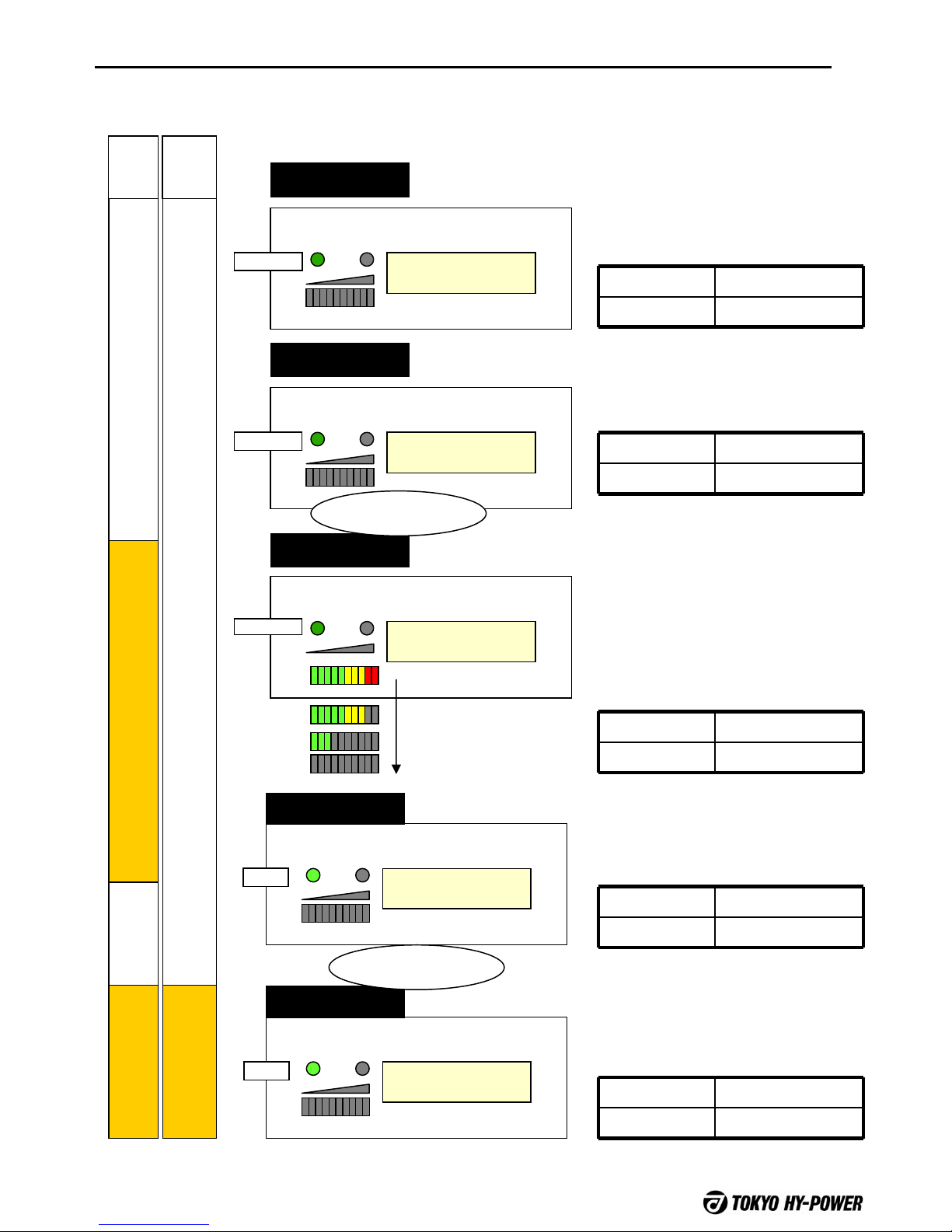
10. Flow of Tuning Sequence
Auto tuning is completed after completing the following four steps of the tuning operation. These
steps are common for all the operating modes.
14MHz WAIT NON
C1=12 C2=19 ANT1
READY WARNING
Fast Blink
14MHz STBY NON
C1=12 C2=19 ANT1
READY WARNING
Slow Blink
14MHz TUNE NON
C1=12 C2=19 ANT1
READY WARNING
Slow Blink
14MHz RADY NON
C1=12 C2=19 ANT1
READY WARNING
Lights
14MHz RADY NON
C1=12 C2=19 ANT1
READY WARNING
Lights
Presetting
Stand-by
Tuning start
Tuning Finish
Linear Ready
When band (or freq.) is changed,
variable capacitors will shift to
best pre-set positions.
It takes a few seconds.
X-ceiver RX (TX inhibit)
Linear Thru (TX inhibit)
Pre-set finished, and ready for
auto tuning to start.
X-ceiver RX (TX possible)
Linear Thru
Receiving the carrier from the x-
ceiver, auto tuning starts.
Tuning finishes in a few seconds.
*For the frequency counter mode,
it is required to start up by
pressing ENTER button.
X-ceiver TX possible
Linear Thru
When auto tuning finishes,
READY lamp lights, and tuning is
completed.
X-ceiver TX possible
Linear Thru
RX
Thru
TX
TX
RX
Amp
ON
Returning to receive state once,
and if the x-ceiver is keyed, linear
will be ready to work.
X-ceiver TX possible
Linear TX possible
TRX Linear
Transmit
Back to Receive Once
HC-1500AT
14
FUSE
FUSE
ANTTRX
SEND AC IN
GND
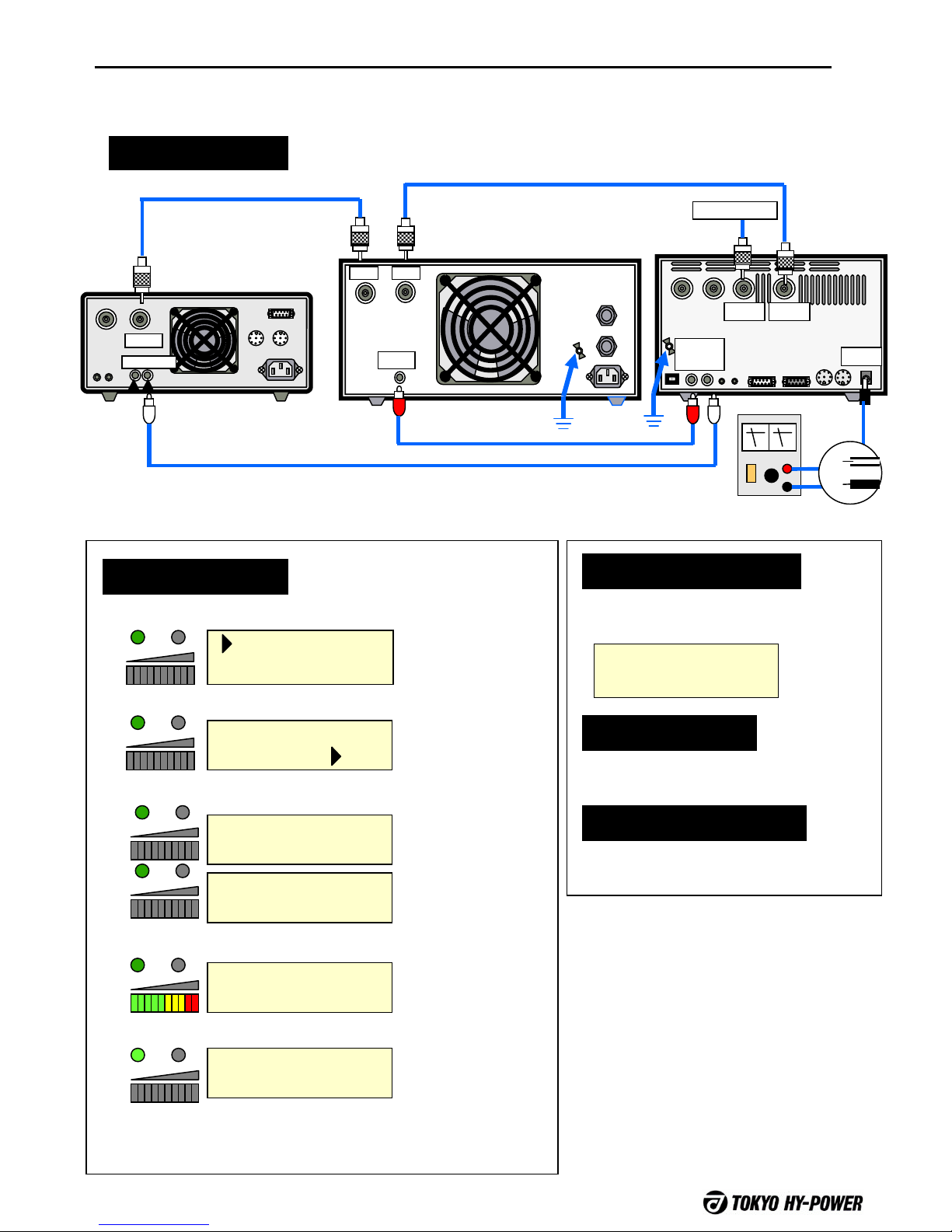
11-1. Setting / Manual Band / ANT Port Selection
Connection
ANT
RELAY
X-Ceiver
Coax Cable
ANT 3 ANT 2 ANT 1
CONTYAESU
KENWOOD
I N
TRX
OUT
CIVSTBY
I N
OUT
I N
OUT DC12V
HC-1500AT
RCA Plug Cable
Coax Cable
This operation method is used if the operator wants to manually select the band and ANT port.
Linear HC-1500AT
ANT1 TRX
STBY
OUT IN DC IN
DC Power Supply
+
Setting of HC-1500AT
Setting of
Linear
None
Setting of Transceiver
None
Interface = NON
Setting Sequence
1.82Mz STBY NON
C1=12 C2=19 ANT1
14MHz FUNC NON
C1=12 C2=19 ANT1
(1) Band Set
14MHz FUNC NON
C1=12 C2=19 ANT1
14MHz WAIT NON
C1=12 C2=19 ANT1
14MHz STBY NON
C1=51 C2=55 ANT1
14MHz TUNE NON
C1=51 C2=55 ANT1
14MHz RADY NON
C1=53 C2=45 ANT1
Set with FUNCTION
button and SELECT
dial.
(2) Ant. Select
(3) Return to Ready Mode
(4)Receiving the carrier from the x-ceiver, tuning starts.
(5) Finishes in a few seconds.
(6) Return to receive state, and the linear is no longer
bypassed.
Antenna should be
selected for each
band.
WAIT sign may take
a few seconds.
It may take a few
seconds to complete
the tuning.
Linear is still
bypassed at this
stage.
To Antenna

HC-1500AT
15
11-2. Setting / FRQ (Freq. Count Method)
Connection
Auto band change is accomplished through the built-in frequency counter without using the band data
cables.
Setting of HC-1500AT
Setting of Linear
None
Setting of Transceiver
None
Interface = FRQ
Setting Sequence
1.822 STBY FRQ
C1=12 C2=19 ANT1
1.822 FUNC FRQ
C1=12 C2=19 ANT1
(1)Antenna Select
1.822 STBY FRQ
C1=12 C2=19 ANT1
Antenna port
should be
selected for
each band.
TXCW is
displayed on the
LCD, and waits
for RF carrier
from radio
1.822 TXCW FRQ
C1=12 C2=19 ANT1
EnF
14.20 CONT FRQ
C1=12 C2=19 ANT1
14.20 WAIT FRQ
C1=12 C2=19 ANT1
14.20 TUNE FRQ
C1=12 C2=19 ANT1
14.20 RADY FRQ
C1=12 C2=19 ANT1
Detects freq of
received carrier.
Presets the
network with the
recognized
frequency.
Auto tuning
completed.
It can take up to
6 sec. max.
CAUTION
Freq. counter will not self-start.
Initiate the frequency counter by
transmitting when your operating band has
changed.
Time out
Transmit the carrier within five seconds
after the ENTRY button is pressed.
Five watts minimum of RF power is
required.
Small PWR levels will lead to a Freq.
counting error.
FUSE
FUSE
ANTTRX
SEND AC IN
GND
ANT
RELAY
X-Ceiver
Coax Cable
ANT 3 ANT 2 ANT 1
CONTYAESU
KENWOOD
I N
TRX
OUT
CIVSTBY
I N
OUT
I N
OUT DC12V
HC-1500AT
RCA Plug Cable
Coax Cable
HC-1500AT Power Cord
Linear HC-1500AT
ANT1 TRX
STBY
OUT IN DC IN
DCRS.
+
RCA Plug Cable
(2)Return to Ready Mode
(3)Initiate the counter with ENTRY button
(4)Transmit the carrier and initiate the tuning.
(5) Return to receive state once, and the linear is no longer
bypassed.
To Antenna

HC-1500AT
16
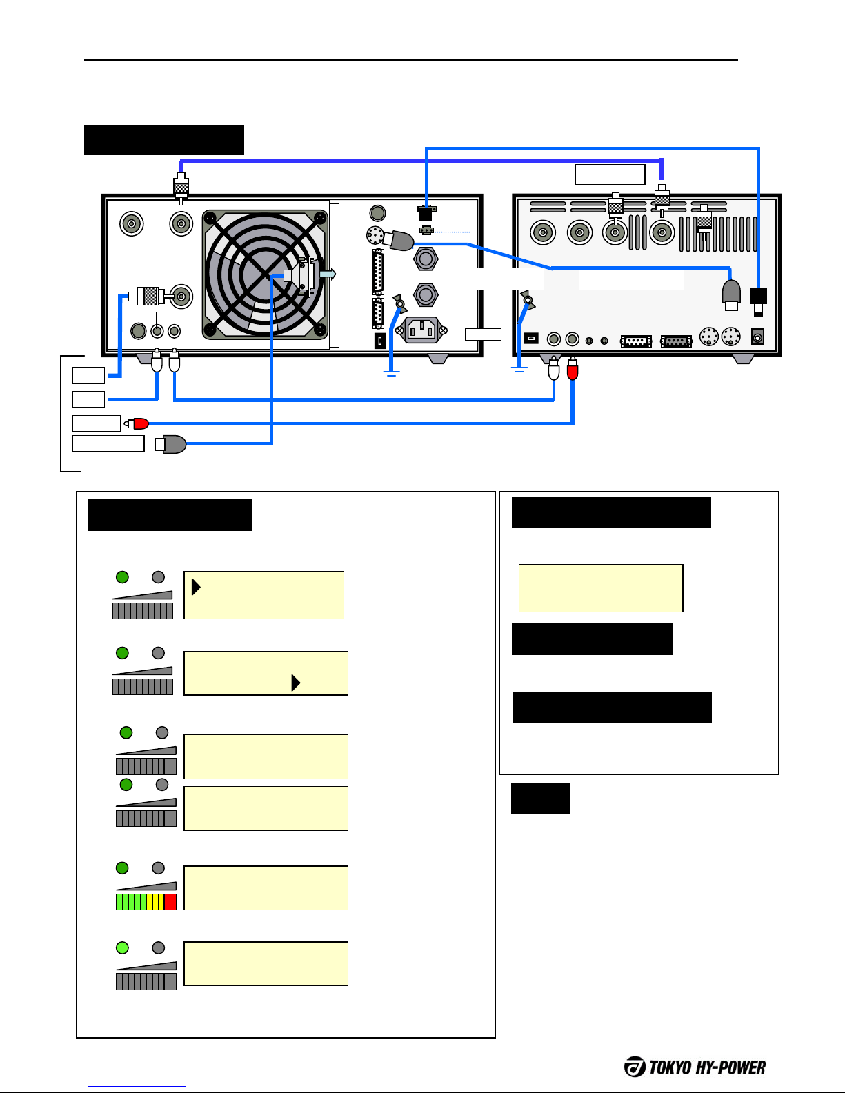
Following is a connection example using ICOM CI-V. If the linear is other than THP’s, linear band setting
controls must be manually set.
Setting of HC-1500AT
Setting of Linear
CI-V combination
Setting of Transceiver
Interface = CIV
Setting Sequence
1.82Mz STBY CIV
C1=12 C2=19 ANT1
14MHz FUNC NON
C1=12 C2=19 ANT1
(1)Antenna Select
14MHz WAIT NON
C1=12 C2=19 ANT1
14MHz STBY NON
C1=51 C2=55 ANT1
14MHz TUNE NON
C1=51 C2=55 ANT1
14MHz RADY NON
C1=53 C2=45 ANT1
Antenna should be
selected for each
band.
FUSE
FUSE
ANT B ANT A
INPUT
ALC ADJALC
SEND
TUNER
SELECT
AC IN
FUSE
FUSE
REMOTE
DC OUT
12V1A
CONT
SERIAL
USB
GND
AC IN
HL-2500FX
ANT 3 ANT 2 ANT 1
CONT
YAESUKENWOOD
I N
TRX
OUT
CIVSTBY
I NOUT
I NOUT DC12V
To Antenna
HC-1500AT
Coax Cable
CI-V BAUD RATE: 9600(bps)
CI-V ADDRESS: 5ch
CI-V Transceive: ON
CI-V with IC-731: OFF
* Refer to ICOM manual for
details.
ANT
ALC
SEND
REMOTE
To ICOM
ICOM Cable
RCA Plug Cable
CI-V Cable
RCA Plug Cable
11-3. Setting / ICOM CI-V
(2)Return to STBY Mode
(3)Transmit the carrier and initiate the tuning.
(4)Tuning will be finished in a few seconds.
(5) Return to receive state once, and the linear is no longer
bypassed.
“WAIT” may take
approx. 3 seconds.
It may take approx.
3 seconds before
tuning is completed.
Linear is still
bypassed at this
stage.
Connection Example with HL-2500FX HC-1500AT Power Cord
HC-1500AT
17
FUSE
FUSE
ANT B ANT A
INPUT
ALC ADJALC
SEND
TUNER
SELECT
AC IN
FUSE
FUSE
REMOTE
DC OUT
12V1A
CONT
SERIAL
USB
GND
AC IN
ANT 3 ANT 2 ANT 1
CONT
YAESUKENWOOD
I N
TRX
OUT
CIVSTBY
I NOUT
I NOUT DC12V
HC-1500AT
AC IN
HL-2500FX To Antenna
Connection
For YAESU x-ceiver and using a THP HL-2500, HL-2.5KFX, or HL-1,5KFX amplifier, it is recommended to
connect the x-ceiver and linear with a YAESU band cable. Also connect the cable between the amplifier and
HC-1500AT using the Tokyo Hy-Power tuner interface cable.
Setting Sequence
14MHz FUNC NON
C1=12 C2=19 ANT1
(1)Set the Band (for 1.8 and 35MHz)
14MHz FUNC NON
C1=12 C2=19 ANT1
14MHz WAIT NON
C1=12 C2=19 ANT1
14MHz STBY NON
C1=51 C2=55 ANT1
14MHz TUNE NON
C1=51 C2=55 ANT1
14MHz RADY NON
C1=53 C2=45 ANT1
Set the band with
FUNCTION button
and SELECT dial.
Setting of HC-1500AT
Setting of Linear
YAESU mode
Setting of Transceiver
None
Interface = YAE
1.822 STBY FRQ
C1=12 C2=19 ANT1
Note
For 1.8 and 3.5MHz band only, please set the
band minutely when the radio is YAESU.
Bands are divided into several segments as follows.
Manually select the nearest channel to your actual
operating frequency.
1.8MHz
1.80Mz·1.82Mz·1.85Mz·1.87Mz·1.90Mz·1.92Mz·1.9
5Mz·1.97Mz
3.5MHz
3.5MHz·3.6MHz·3.7MHz·3.8MHz·3.84Mz·3.94Mz
BAND DATA
TX-GND
ALC
ANT
To YAESU X-ceiver
RCA Plug Cable
YAESU Band Cable
RCA Plug Cable
Coax Cable HC-1500AT DC Power Cord
11-4. Setting / Tokyo Hy-Power Interface
(2)Antenna Select
(3)Return to STBY mode
(4)Transmit the carrier and imitate the tuning.
(5)Tuning will be finish in a few seconds.
(6) Return to receive state once, and the linear is no longer
bypassed.
Antenna should be
selected for each
band.
“WAIT” may take
approx. 3 seconds.
It may take approx. 3
seconds before
tuning is completed.
Linear is still
bypassed at this
stage.
THP tuner cable

HC-1500AT
18
AC IN
ANT 3 ANT 2 ANT 1
CONT
YAESU
KENWOOD
I N
TRX
OUT
CIVSTBY
I NOUT
I NOUT DC12V
HC-1500AT
When the x-ceiver is YAESU, and linear is other than a THP amplifier, it is recommended to connect
the x-ceiver and HC-1500AT with the YAESU band data cable, then set the amplifier parameters
manually..
FUSE
FUSE
ANTTRX
SEND
AC IN
GND
To Antenna
HC-1500AT
RCA Plug Cable
Coax Cable
DC Power Cord
Linear
Connection
ANT
BAND DATA
TX-GND
Setting Sequence
14MHz FUNC NON
C1=12 C2=19 ANT1
(1)Set the Band (minutely for 1.8 and 35MHz)
14MHz FUNC NON
C1=12 C2=19 ANT1
(2)Antenna Select
(3)Return to STBY mode
(4)Transmit the carrier and imitate the tuning.
14MHz WAIT NON
C1=12 C2=19 ANT1
14MHz STBY NON
C1=51 C2=55 ANT1
14MHz TUNE NON
C1=51 C2=55 ANT1
14MHz RADY NON
C1=53 C2=45 ANT1
(5)Tuning will be finished in a few seconds.
(6) Return to receive state once, and the linear is no longer
bypassed.
Set the band with
FUNCTION button
and SELECT dial.
Antenna should be
selected for each
band.
“WAIT” may take
approx. 3 seconds.
It may take approx.
3 seconds before
tuning is completed.
Linear is still
bypassed at this
stage.
Setting of HC-1500AT
Setting of Linear
YAESU mode
Setting of Transceiver
None
Interface = YAE
1.822 STBY FRQ
C1=12 C2=19 ANT1
Note
For 1.8 and 3.5MHz band only, please set the
correct band segment when using YAESU
radios.
Bands are divided into several segments as follows.
Manually select the nearest band segment to your
actual operating frequency.
1.8MHz
1.80Mz·1.82Mz·1.85Mz·1.87Mz·1.90Mz·1.92Mz·1.9
5Mz·1.97Mz
3.5MHz
3.5MHz·3.6MHz·3.7MHz·3.8MHz·3.84Mz·3.94Mz
To YAESU X-ceiver
11-5. Setting / YAESU with Other
Linear

HC-1500AT
19
AC IN
ANT 3 ANT 2 ANT 1
CONT
YAESUKENWOOD
I N
TRX
OUT
CIVSTBY
I NOUT
I NOUT DC12V
HC-1500AT
Connection Example with HL-2500FX
Combination with COM port of KENWOOD transceiver.
If linear amp is other than THP’s, the linear should be set manually.
Setting of HC-1500AT
Setting of Linear
KENWOOD mode
Setting of Transceiver
Interface = KEN
Setting Sequence
1.82Mz STBY KEN
C1=12 C2=19 ANT1
14MHz FUNC NON
C1=12 C2=19 ANT1
(1)Antenna Select
(2)Return to STBY Mode
(3)Transmit the carrier and initiate the tuning.
14MHz WAIT NON
C1=12 C2=19 ANT1
14MHz STBY NON
C1=51 C2=55 ANT1
14MHz TUNE NON
C1=51 C2=55 ANT1
14MHz RADY NON
C1=53 C2=45 ANT1
(4)Tuning will be finished in a few seconds.
(5) Return to receive state once, and the linear is no longer
bypassed.
Antenna should be
selected for each
band.
“WAIT” may take
approx. 3 seconds.
It may take approx.
3 seconds before
tuning is completed.
Linear is still
bypassed at this
stage.
FUSE
FUSE
ANT B ANT A
INPUT
ALC ADJALCSEND
TUNER
SELECT
AC IN
FUSE
FUSE
REMOTE
DC OUT
12V1A
CONT
SERIAL
USB
GND
ANT A
INPUT
HL-2500FX
To Antenna
HC-1500AT
RCA Plug Cable
RCA Plug Cable
Coax Cable
DC power Cord
CONT
DC IN
SEND
Communication speed: 9600 bps
Stop bit: 1 bit
* For details, refer to
KENWOOD manual.
ALC
ANT
SEND
COM
To KENWOOD x-ceiver
11-6. Setting / KENWOOD
Table of contents
Other Tokyo Hy-Power Tuner manuals

Popular Tuner manuals by other brands


Sangean
Sangean MMR-99 user manual

Marantz
Marantz AV8801 Getting started

Dynalink
Dynalink A 2704B operating instructions

Metra Electronics
Metra Electronics AHDT-01 installation instructions

Pioneer
Pioneer DC-888Z operating instructions

Panasonic
Panasonic WJND200 - NETWORK DISK RECORDER operating instructions