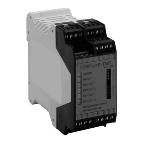
Tokyo Keiki VD-10 User manual

Doc. No. KF15-001A
VIBRATION DETECTOR
VD-10
INSTRUCTION MANUAL
TOKYO KEIKI INC.
Measurement Systems Company


1
1. PRECAUTIONS
1.1 SAFETY PRECAUTIONS
This manual is to prevent in advance the damage to harm and their property for those who want
to
use our product, VD-10, they are important contents for use safely and correctly the VD-10. The
following content (display, graphical symbols) to understand better, read the text carefully.
As this manual can be referred immediately when needed, please keep in easy-to-use location.
DESCRIPTION OF SAFETY SYMBOLS
Meaning of the safety symbols that is displayed in the document and the body of the VD-10 are
as
follows.
Display
Meaning of display
DANGER
When the wrong handling, ignoring this display, the operator
are assumed the risk of death or serious injury.
WARNING
When the wrong handling, ignoring this display, there is a
possibility that the operator to death or serious injury.
CAUTION
When the wrong handling, ignoring this display, the operator
get hurt, or property damage is assumed that occur.
LABELSAND ATTACHED PLACE
The VD-10 has been affixed equipment nameplate shown below.

2
1.2 USAGE PRECAUTIONS
Performance of the VD-10 is sufficiently exhibited, and in order to safely use
the VD-10, please be used with caution in the following matters.
DANGER
When you use the remote reset function of the VD-10, please
adhere to the both "reset power rating" and "reset coil rating".
There is a risk of ignition by the internal temperature rise when not
satisfy these ratings.
CAUTION
If you do not conform to the following matters,
there is a
possibility that the VD-10 to malfunction.
Given that you use in the acceleration range.
Predetermined be used in the range of ambient temperature and
humidity.
Always read this manual carefully, make the zero adjustment and
the acceleration setting. Misconfigured and false adjustment may
cause a malfunction.
Do not attempt to tamper or decomposition of the product. It may
cause electric shock or malfunction.
If you lose this manual, please contact us or our distributor.

3
2. INTRODUCTION
This manual, including the safety instructions on VD-10, specification, construction, installation,
operation method, and has been described in detail, such as failure and its countermeasures. The
VD-10 is fully understood, please use it correctly.
2.1 COMPLIANCE REQUIREMENTS
Instructions that the user should observe about this manual are as follows.
a. Since this handling the manual has been described that important, please be sure to read to the
last.
b. This manual is required when handling the VD-10.As read this manual at any time, and decided
to store personnel and storage location, please keep it in a safe place.
c. Seller of VD-10, must deliver this manual at hand of people who actually use the VD-10.
d. If you lose this manual, please supplemented with contact to manual your dealer.
e. If the warning labels and equipment nameplate has are peeling or dirty, please supplemented
with them.
2.2 NOTES
If there is a different description content and approval drawings by customer's specifications, we
will give priority to the approval drawings.
2.3 PROHIBITIONS AND NOTES FOR EQUIPMENT PROTECTION
a. Do not drop the VD-10. Also, please do not give a shock such as hit.
b. Do not use other than the provisions of the operating environment.
c. Do not use other than the provision of power.
d. Do not use the wire which are scratches and peeling in the coating.
e. Since the inside of the VD-10 has a high-voltage part (more than 100V), please do not touch the
absolutely inside the terminal portion and equipment while power is being supplied. Installation
work, wiring work, should be done after confirming that it is not energized.
f. Absolutely that you do not modify or disassemble the VD-10. Please contact us or dealer when
the abnormality in the VD-10 has occurred.
g. VD-10 cannot be used in hazardous areas.

4
[Blank page]

5
INDEX
1. PRECAUTIONS ............................................................................................................1
1.1 SAFETY PRECAUTIONS ...........................................................................................1
DESCRIPTION OF SAFETY SYMBOLS...........................................................................1
LABELS AND ATTACHED PLACE ..................................................................................1
1.2 USAGE PRECAUTIONS.............................................................................................2
2. INTRODUCTION..........................................................................................................3
2.1 COMPLIANCE REQUIREMENTS...............................................................................3
2.2 NOTES.......................................................................................................................3
2.3 PROHIBITIONS AND NOTES FOR EQUIPMENT PROTECTION ................................3
INDEX..................................................................................................................................5
3. Summary.......................................................................................................................7
4. Operating principle.........................................................................................................9
5. Specifications ..............................................................................................................11
6. Installation...................................................................................................................15
6.1 Fitting ......................................................................................................................15
6.2 Wiring......................................................................................................................15
6.3 Installation................................................................................................................15
6.4 Connection for the Remote reset function.....................................................................16
7. Adjustment..................................................................................................................17
7.1 Outline .....................................................................................................................17
7.2 Zero point adjustment ................................................................................................17
7.3 Setting of acceleration................................................................................................17
8. Maintenance ................................................................................................................19

6
[Blank page]

7
3. Summary
There are many cases where, like pumps and compressors in the process industry, their normal
operation is quite indispensable for the smooth operation of whole equipment. If such machines
should be troubled, resulting in impossibility of operation, danger will be attended or products and
materials under manufacture will be damaged wastefully if whole equipment is not stopped
immediately. In addition to the above, the suspension of the whole equipment due to repairing of
the troubled machines will do immeasurable damage.
Investigating the causes of trouble of machines like pump and compressor, no trouble will be
caused suddenly while operating. The causes of trouble are the increase in play due to loosening of
screws or wear of machine parts, entry of foreign matter in the sliding section, wear of bearings,
spalls due to fatigue and poor lubrication etc. If left as they are, the trouble will become serious or
cause another trouble, resulting in impossibility of whole equipment usually. In such a case, if
abnormality can be detected at an early stage of trouble, the pump or compressor can be shifted to
spare units, resulting in enabling you to repair the trouble machine without stopping the operation
of
whole equipment.
Vibration is generated at normal operating state in the case of rotating and reciprocating
machines.
If these machines should be troubled, an abnormal vibration will be generated
overlapping with the normal vibration. Though different depending on the troubled position, the
abnormal vibration is generated as a vibration of irregular waveform of higher frequency than that
at normal operating condition. As trouble progresses, the frequency and amplitude will be increased.
Because of the amplitude of the abnormal vibration during earlyfailures is small, it is difficult to
detect
by conventional vibrometer. If the amplitude of the abnormal vibration should be detected
by such conventional vibrometer, trouble will have become considerably serious, resulting in
requiring a considerably a long repair time and a large amount of repair cost. The VD-10 is a
vibration detector which is quite different from vibrometer in the operating principle for detection
of abnormality. Then the VD-10 cannot show the continuous measuring value of vibration
acceleration. The vibration detector is used as an alarm generator against abnormal vibration. If
vibration acceleration due to abnormal vibration exceeds a set value, an alarm signal will be output
from the contact switch of the VD-10.
Generally, vibration acceleration of a machine is calculated by amplitude and frequency of the

8
vibration. This calculation is applied to an ideal sine vibration. If actual waveform of vibration of a
machine may be deformed, vibration acceleration will be larger than the said value naturally.
Generally, vibrations at operation of machines are extremely complicated and that is very
difficult to analyze. For the sake of simplicity, vibration is simplified to be considered as a sine
wave.
If an abnormal phenomenon is occurred in a machine while operating, an abnormal vibration of
high frequency will be generated overlapping with normal.
That is, if the frequency of abnormal vibration is n times as large as number of vibrations at
normal condition,
DISPLACEMENT X = Xo sin (2πft) + X' sin (2πnft)
SPEED V = 2πfXo cos (2πft) + 2πnfX' cos (2πnft)
ACCELERATION A= -4π2 f2 Xo sin (2πft) - 4π2 n2f2X' sin (2πnft)
Where,
Xo: Vibration amplitude at normal operation
X': Amplitude of abnormal vibration
f: Vibrating frequency at normal operation
t: Time
MAXIMUM DISPLACEMENT, MAXIMUM SPEED AND MAXIMUM ACCELERATION:
MAXIMUM DISPLACEMENT Xmax = Xo + X'
MAXIMUM SPEED Vmax = 2πf (Xo + nX')
MAXIMUM ACCELERATION Amax = 4π2f2 (Xo + n2X')
Accordingly, especially in maximum acceleration, if the n is very large, the ratio of acceleration
component due to abnormal vibration is found to be large even if X' is not so large. If the VD-10
detecting the abnormal vibration byacceleration in place of amplitude is used, abnormality will be
detected easily at an early stage of trouble. Even in case abnormal vibration is generated in a form
of increase of vibration amplitude, the VD-10 will be operated effectively.

9
4. Operatingprinciple
As illustrated in Fig.1, the armature is supported by a spring joint and one end of it can be
operated in a space between two permanent magnets. The other end of the armature receives a
force of the adjusting spring compressed by a sensitivity adjustment screw. When reset by
pushing the reset button, the tip end of the armature will be attracted by the lower magnet and reset.
At this state, if it receives a vibration in the direction of the sensing shaft shown in the Fig.1, a
moment of force separating it from the lower magnet will be generated around the spring joint of the
armature. The adjustment spring gives a moment of force in the direction of separating the
armature from the lower magnet to the part around the spring joint in the same way. If the sum of
the moments of force is larger than the moment given to the part around the spring joint upon
attracting the armature by the lower magnet, the armature will be separated from the lower stop pin,
resulting in being attracted by a magnet for latch. The operation of the armature operates the
micro
switch, giving a warning.
Sensitivity adjustment screw Reset button
Lock nut Sensing
Axis
Adjusting spring
Armature
fitting plate
Leaf spring
Pivot
Micro
Switch
Reset coil
Magnet for latch
Gap
Holding magnet
Stop pin
Fig.1 CONSTRUCTION OF VIBRATION DETECTOR
The sensitivity adjustment screw changes the compression force of the spring which acts on the
armature by controlling the compression of the adjusting spring and sets the accelerating level at
which the detector is operated. For resetting the detector, push the reset button with hand and push
down the armature.
For remote resetting, if an electric current is supplied to the reset coil temporarily, it can be reset

10
veryeasily.
As mentioned above, the mechanism and operating principles of the VD-10 are very simple.
For the main parts setting acceleration, especially for permanent magnets, ALNICO permanent
magnet having a large magnetism has been adopted and the magnetic path has a very small gap and
is
not influenced by external magnetism.

11
5. Specifications
Setting range of vibration acceleration 0 - 44.1 m/s2(0 - 4.5 G)
/Recommended setting range 4.9 - 44.1 m/s2(0.5 - 4.5 G)
/Adjust sensibility 9.8 m/s2 (1 G) per rotation
Notes: These values are based on the condition the detector is fixed on horizontal.
Frequency range 0 - 300 Hz
Accuracy ±2.21 m/s2(±0.225 G)
Alarm output
/Output type Micro switch contact
/ / SPDT (Single-pole Double-throw)
/Contact current capacity 3 A at 125/250 Vac
0.5 A at 125 Vdc
0.25 A at 250 Vdc
Reset function
/Operation method Manual reset bymechanical switch
Remote reset by electromagnetic switch
/Ratings for remote reset
//Reset voltage 100 - 125 Vac (50/60 Hz)
100 - 125 Vdc
//Reset current 0.23 A
//Maximum reset time 5 minutes upon reset voltage 100 V
3 minutes upon reset voltage 110 V
2.5 minutes upon reset voltage 115 V
2 minutes upon reset voltage 125 V
Operatingenvironment
/Ambient temperature -20 - +80 degree C
/Ambient humidity 10 - 95 %RH
Note: No condensation

12
Waterproof property IP X4
Material
/Case Aluminum alloy casting (AC4C)
/Coating Melamine resin baking finish / Gray hammer tone
/Cover Aluminum alloy plate (A5052)
Mass Approx. 0.9 kg
Dimensions Refer to the Fig.2 Outline of the VD-10
Conduit Female thread / Rc 3/4 (PT 3/4)
Wiring
/recommended electric wire conductor diameter 1.25mm2 and over
/terminals for wiring (see diagram below: internal connection diagram)
1Remote reset terminals
2(Reset power source: 100 –125 Vac/Vdc)
3 Alarm output terminals (Normally open contact)
4
5 Alarm output terminals (Normally close contact)
* When the manual reset, the Remote reset terminals should be open.

13
95
79
120
12
75
32
136
4-φ9
Mounting hole
Reset button
Gasket
(EPR)
Conduit hole
Fig.2 Outline of the VD-10

14
[Blank page]

15
6. Installation
See the section 1. PRECAUTION and 2. INTRODUCTION
6.1 Fitting
As illustrated in Fig.1, the VD-10 is operated against the acceleration in the vertical direction to
the fitting plate surface. Therefore, in the case of general rotating machines, it must be fitted in
such a way that the fitting plate surface is vertical to the radial direction of the shaft. Fit it to the
machine body with bolts directly or through a mounting bracket. The mounting bracket must have
thickness larger than 9 mm to have a high rigidity.
In the vibration of general machines, there is a difference in amplitude depending on the
installation place. Install the detector in optimal places for operation. For it, referring to the
paragraph "SETTING", check the vibration level at each place upon investigation by holding it with
hand or fitting it temporarily and fix at the best position. To maintain waterproof performance,
please tighten the cover screws diagonally and with torque is 3 N·m.
6.2 Wiring
The VD-10 vibrates together with a machine. Therefore, it is not desirable to provide wiring
in such a way that the vibration is prevented. Wiring is provided through a 3/4B conduit pipe.
When the vibrating amplitude is less than 0.1 mm, the conduit pipe can be connected with the
conduit hole of the detector directly. However, if the amplitude is larger than 0.1 mm, a flexible
conduit must be used between the holes of conduit pipe and detector conduit so that the movement
of the detector is not held.
Use wires with 1.25 mm2 and over for wiring. The number of wires is different according to
each case. Refer to the internal connection diagram.
6.3 Installation
1) For the purpose of dust-proofing, carry out the installing operation with the cover attached
when it is fitted and conduit pipes are connected.
2) After finishing the installation of the detector, remove the cover and pass the wire through
the conduit pipe or gland. Provide an ample length of wire enough to reach the terminal
board.
3) Strip the end of wire approx. 6 mm and fit the terminal piece (screw hole dia. 3.2 mm,
width 7.5 mm or less).
4) Connect the wires to the terminal.
5) Fit the cover temporarily until adjustment is finished.

16
6.4 Connection for the Remote reset function
Instead of manually resetting the VD-10, it is possible to reset it remotely. At the terminal #1
and #2, connect a power source and a switch in series. AC power source and DC power
source are available for the power source.
1
2
Don't
connect
anything here.
Reset switch
+
DC or AC
-
3 Reset power source:
100 –125 Vdc or Vac
4
5
Don't connect anything between the terminal #2 and #3. These are used for internal
wiring.

17
7. Adjustment
See the section 1. PRECAUTION and 2. INTRODUCTION
7.1 Outline
When the sensitivity adjustmentscrew of the detector is turned clockwise, the compression force
of
the spring which acts on the armature will be increased. Therefore, the detector will operate in
small
acceleration. When turned counterclockwise, the compression force of the spring will
become
weak. So the detector will operate in large acceleration. Adjustment has been made in
such a way that one revolution of the sensitivity adjustment screw of the detector is equal to 9.8m/s2
(1G). The dial has a 10-equally divided scale. Therefore, 1 scale division is equal to 0.98m/s2
(0.1G).
Adjustment is made in the following sequence.
7.2 Zero point adjustment
In the detector, the effects given to the armature by acceleration of gravity are different according
to fitting angle. Therefore, in state equipped with the detector, seek the zero point.
Stop the machine of target and take off the cover of the detector. Turn the sensitivity adjustment
screw counterclockwise 2 times, and press the reset button to reset the detector. Then, turn the
sensitivity adjustment screw clockwise slowly until the armature tripped. The trip shows in sound.
This is the point where the detector is operated with zero acceleration and called "ZERO POINT".
Repeat this act few times to determine the ZERO POINT.
7.3 Setting of acceleration
In order to set acceleration of the detector, the acceleration level of normal vibration at the time
of
operation must beforehand. Start the machine of target to its constant operating condition.
Then,
return the sensitivity adjustment screw from the ZERO POINT sought beforehand by 3 turns
counterclockwise. Then, turn it slowly clockwise and seek for the position where the armature is
tripped on the dial. This point is the "NORMAL OPERATING POINT" which is the one where
the
detector is operated by vibration acceleration at normal operation.
The difference in scale divisions between the ZERO POINT and the NORMAL OPERATING
POINT is the normal G-level of the operating machine. Usually, set acceleration is 50% more of
the acceleration level at normal operation.
Accordingly, for instance, if the normal G-level is 18 scale divisions from the ZERO POINT,
turn the sensitivity adjustment screw by 9 scale divisions more counterclockwise from the

18
NORMAL OPERATING POINT. The acceleration of 2.7G is set to the detector.
After finishing the setting of acceleration, fix the adjustment knob protection cover of the
detector and reset it. Then, connect the wires to the output terminal. Please tighten the
cover screw diagonally and with torque 3 N·m.
In such a way, the detector is set at such a value as 50% more or so of that at constant
operation.
If an alarm is given frequently after the machine starts operation, correct the set
value little by little
in order to seek for the best set value.
Table of contents
Popular Security Sensor manuals by other brands
YOKOGAWA
YOKOGAWA TB830D user manual

Crow
Crow GENIUS Installation instructions and instructions for use
Siemens
Siemens FDT421 installation instructions

pdlux
pdlux PD-MV1018A instructions

Lince
Lince BOBBY-AM Installation, operation and maintenance manual

ALERTON
ALERTON MS/TP Microset II Installation and operation guide

