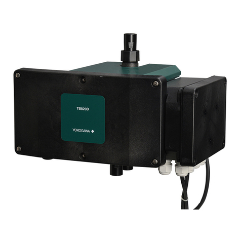
YOKOGAWA TB830D User manual

User’s
Manual TB830D
Surface Scattering Light Turbidity
Detector
IM 12E04B40-02EN
IM 12E04B40-02EN
1st Edition

i
IM 12E04B40-02EN
<INTRODUCTION>
1st Edition : Mar. 08, 2023-00
uINTRODUCTION
Thank you for purchasing TB830D Surface Scattering Light Turbidity Detector.
This User’s Manual contains all essential information for the user to make full use of TB830D.
Please read the following respective documents before installing and using the instrument.
The related documents are listed as follows.
General Specications
Contents Document number Note
TB830D, FLXA402T Surface Scattering
Light Turbidity Detector GS 12E04B40-01EN Online manual
“EN” in the document number is the language code.
User’s Manual
Contents Document number Note
TB830D Surface Scattering Light
Turbidity Detector
Start-up and Safety Precautions
IM 12E04B40-01EN Attached to the product (printed manual)
(This manual)
TB830D Surface Scattering Light
Turbidity Detector IM 12E04B40-02EN Online manual
FLXA402T Liquid Analyzer for Turbidity
and Chlorine
Start-up and Safety Precautions
IM 12A01G01-01EN Attached to the product (printed manual)
FLXA402T Liquid Analyzer for Turbidity
and Chlorine
Installation and Wiring
IM 12A01G01-02EN Online manual
FLXA402T Liquid Analyzer for Turbidity
and Chlorine
Operation of Converter
IM 12A01G01-03EN Online manual
FLXA402T Liquid Analyzer for Turbidity
and Chlorine
Operation of pH
IM 12A01G02-01EN Online manual
FLXA402T Liquid Analyzer for Turbidity
and Chlorine
Operation of SC
IM 12A01G03-01EN Online manual
“EN” in the document number is the language code.
An exclusive User’s Manual might be attached to the products whose sux codes or option codes
contain the code “Z” (made to customers’ specications). Please read it along with this manual.
Technical Information
Contents Document number Note
FLXA402T Liquid Analyzer for Turbidity
and Chlorine
MODBUS Communication
TI 12A01G01-62EN Online manual
“EN” in the document number is the language code.
You can download the latest documents from our website. Scan QR code.
http://www.yokogawa.com/an/xa402t/download/
Refer to each corresponding manual for other related products.
No. IM 12E04B40-02EN 1st Edition: Mar. 2023 (YK)
All Rights Reserved Copyright © 2023, Yokogawa Electric Corporation

ii
IM 12E04B40-02EN
<INTRODUCTION>
1st Edition : Mar. 08, 2023-00
n Notes on Handling User’s Manuals
• Please hand over the user’s manuals to your end users so that they can keep the user’s
manuals on hand for convenient reference.
• Please read the information thoroughly before using the product.
• The purpose of these user’s manuals is not to warrant that the product is well suited to any
particular purpose but rather to describe the functional details of the product.
• No part of the user’s manuals may be transferred or reproduced without prior written
consent from YOKOGAWA.
• YOKOGAWA reserves the right to make improvements in the user’s manuals and product at
any time, without notice or obligation.
• If you have any questions, or you nd mistakes or omissions in the user’s manuals, please
contact our sales representative or your local distributor.
n Drawing Conventions
Some drawings may be partially emphasized, simplied, or omitted, for the convenience of
description.
Some screen images depicted in the user’s manual may have dierent display positions or
character types (e.g., the upper / lower case). Also note that some of the images contained in this
user’s manual are display examples.
nTerminology
● Turbidity meter, Turbidity analyzer: TB830D + FLXA402T
● Detector, Detection unit: TB830D detector, TB830D Detection unit
● Converter or liquid analyzer: FLXA402T
n Trademark Acknowledgements
• FLEXA, FLXA and SENCOM are trademarks or registered trademarks of Yokogawa Electric
Corporation.
• All other company and product names mentioned in this user’s manual are trademarks or
registered trademarks of their respective companies.
• We do not use TM or ® mark to indicate those trademarks or registered trademarks in this
user’s manual.

Toc-1
IM 12E04B40-02EN
<CONTENTS>
1st Edition : Mar. 08, 2023-00
TB830D
Surface Scattering Light Turbidity Detector
IM 12E04B40-02EN 1st Edition
CONTENTS
uINTRODUCTION.............................................................................................i
1. OVERVIEW ................................................................................................ 1-1
1.1 Measurement system and structure............................................................... 1-1
1.2 Part Name and Functions ................................................................................ 1-2
1.3 Specications.................................................................................................... 1-2
1.4 Model and Codes .............................................................................................. 1-3
1.5 External Dimensions ........................................................................................ 1-5
1.6 Measurement principle..................................................................................... 1-6
2.
INSTALLATION, PIPING, AND WIRING ..................................................... 2-1
2.1 Piping ................................................................................................................. 2-2
2.1.1 For TB830D-□-□-NN, -A5 (without sampling system) ....................... 2-2
2.1.2 TB830D-□-AJ-A1,-A2,-A3 (with sampling system)............................ 2-3
2.2 Wiring ................................................................................................................. 2-6
2.2.1 SENCOM cable for Turbidity/Chlorine (A) ....................................... 2-10
2.2.2 FLXA402T power supply cable (B).................................................. 2-10
2.2.3
TB830D power supply cable (C), Relay box power supply cable (D)
........ 2-10
2.2.4 Power supply cable (E) .................................................................... 2-11
2.2.5
Without a sampling system and with a Relay box for solenoid valve
......... 2-12
2.3 Desiccant mounting ....................................................................................... 2-14
3. PREPARATION for OPERATION ............................................................. 3-1
3.1 Piping and Wiring Check.................................................................................. 3-1
3.2 Conrming detector condition ........................................................................ 3-1
3.3 Supplying Power and switching operation modes ....................................... 3-2
3.4 Valve operation.................................................................................................. 3-2
3.5 Supply of zero water......................................................................................... 3-3
3.6 Leveling detector (ow rate adjustment) ....................................................... 3-3
3.7 Supply of Cleaning water................................................................................. 3-4
3.8 Running-in operation........................................................................................ 3-4
3.9 Setup of operating parameters........................................................................ 3-4
3.10 Calibration ......................................................................................................... 3-4
3.11 Zero calibration & slope calibration................................................................ 3-5
3.12 Supplying Sample and Adjustment ow rate ................................................ 3-5
3.13 Switch to measurement mode......................................................................... 3-5
4. SETTING PARAMETERS ......................................................................... 4-1
4.1 Measure setting................................................................................................. 4-2

Toc-2
IM 12E04B40-02EN
<CONTENTS>
1st Edition : Mar. 08, 2023-00
4.1.1 Negative value non output ................................................................. 4-2
4.1.2 Turbidity unit select ............................................................................ 4-2
4.1.3 Meas. damping time constant, Maint. damping time constant .......... 4-3
4.1.4 Turbidity warning High/Low limit ........................................................ 4-3
4.1.5 Air denoising setting........................................................................... 4-3
4.2 Cal./Maint. Settings........................................................................................... 4-6
4.2.1 Turbidity value of check tool............................................................... 4-6
4.2.2 Zero shift value, Correction factor...................................................... 4-6
4.2.3 Stability check .................................................................................... 4-6
4.2.4 Wash/Cal. box.................................................................................... 4-6
4.2.5 Calibration setting others ................................................................... 4-6
4.3 Diagnosis setting .............................................................................................. 4-6
4.3.1 Light source diagnosis ....................................................................... 4-6
4.3.2 Dried condition diagnosis................................................................... 4-6
4.3.3 Operating days................................................................................... 4-7
4.4 Communication setting.................................................................................... 4-7
4.5 Automatic cleaning/Automatic zero calibration setting............................... 4-7
4.5.1 Auto sequence for wash/cal............................................................... 4-7
4.5.2 Start date............................................................................................ 4-7
4.5.3
Automatic cleaning/Automatic zero calibration function and wash type
....... 4-7
4.5.4 Auto sequence setting ....................................................................... 4-8
5. FLXA402T sensor menu .......................................................................... 5-1
5.1 WASH ................................................................................................................. 5-2
5.2 Calibration ......................................................................................................... 5-2
5.3 Detail................................................................................................................... 5-2
5.4 Reset op. time.................................................................................................... 5-5
5.5 Setting ................................................................................................................ 5-5
5.6 Maintenance ...................................................................................................... 5-6
5.6.1 Maintenance mode ............................................................................ 5-6
5.6.2 Light source On/O............................................................................ 5-6
5.6.3 SV/Wiper operation............................................................................ 5-6
6. OPERATION .............................................................................................. 6-1
6.1 Turbidity measurement .................................................................................... 6-1
6.2 Air denoising ..................................................................................................... 6-1
6.3 When Water Supply is Cut O ......................................................................... 6-1
6.4 Automatic cleaning/Automatic zero calibration Operation ......................... 6-1
6.5 Stop and restarting operation ......................................................................... 6-1
7. CALIBRATION........................................................................................... 7-1
7.1 Turbidity calculation and calibration menu ................................................... 7-1
7.2 Turbidity standards........................................................................................... 7-3
7.3 Formazin Standard Solution............................................................................ 7-5
7.3.1 Preparing a 4000 NTU Formazin Standard Stock Solution............... 7-5
7.3.2 Preparing a 400 NTU Formazin Calibration Standard Solution ........ 7-6
7.4 Zero Calibration................................................................................................. 7-6

Toc-3
IM 12E04B40-02EN
<CONTENTS>
1st Edition : Mar. 08, 2023-00
7.5 For zero calibration by turning o the light source ...................................... 7-7
7.6 Slope calibration (Check tool) ......................................................................... 7-7
7.7 Slope calibration (Standard solution)............................................................. 7-7
7.8 Auto zero calibration ........................................................................................ 7-8
7.9 Zero shift correction ......................................................................................... 7-8
7.10 Sensitivity correction ....................................................................................... 7-9
7.11 2 points correction............................................................................................ 7-9
7.12 Basic (reference) sensitivity calibration....................................................... 7-10
7.13 Calibration Error.............................................................................................. 7-10
8. MAINTENANCE......................................................................................... 8-1
8.1 Cleaning with cleaning water .......................................................................... 8-1
8.2 Cleaning of Flow cell ........................................................................................ 8-2
8.3 Cleaning of Head tank ...................................................................................... 8-2
8.4 Checking and Replacing Desiccants.............................................................. 8-3
8.5 Pipe Cleaning .................................................................................................... 8-4
8.6 Inspection solenoid valve ................................................................................ 8-5
8.7 Replacing the Zero Turbidity Filter Element .................................................. 8-5
8.8 LED Replacement ............................................................................................. 8-6
8.9 Lens cleaning .................................................................................................... 8-9
8.10 Fuse replacement ............................................................................................. 8-9
8.11 Replacement of the Silicone Tube ................................................................ 8-11
8.12 Checking ow rate (liquid level).................................................................... 8-13
8.13 When Sample Water Supply is Cut O ......................................................... 8-13
9. TROUBLESHOOTING .............................................................................. 9-1
9.1 When an error occurs....................................................................................... 9-1
9.2 When No Error Indication Appears ................................................................. 9-2
Appendix
Automatic cleaning/Automatic zero calibration Sequence App.-1
Customer Maintenance Parts List................................... CMPL 12E01B30-01EN
Revision Information ...............................................................................................i

Blank Page

<1. OVERVIEW> 1-1
IM 12E04B40-02EN 1st Edition : Mar. 08, 2023-00
1. OVERVIEW
Surface Scattering Light Turbidity Detector, composed of Turbidity Detector TB830D and Liquid
Analyzer FLXA402T, is a next-generation analyzer, developed based on years of experience,
combining the reliable measurement principle with our latest digital sensor technology realizing
high eciency in facility operations. The product has successfully extended its life by employing
LED as the light source.
1.1 Measurement system and structure
TB830D is used with FLXA402T Liquid Analyzer for Turbidity and Chlorine. TB830D also can be
used with a sampling system to control the pressure or ow rate of samples.
lTB830D Surface Scattering Light Turbidity Detector
TB830D measures turbidity. The Detection unit consists of the following three parts.
● Flow cell: A sample ows through it. A light beam is emitted from the light source
onto the sample solution.
● Detection unit: An optical system incorporating a Light source, Receiver, and lenses.
Desiccant equipped helps the dryness inside.
● Smart unit: Memory of parameters, the control unit
l FLXA402T Liquid Analyzer for Turbidity and Chlorine (converter)
Displays/Outputs measurement or status of connected detectors or controls detectors.
Refer to IM 12A01G01-03EN for the setup of the display, input/output, or communication.
l Sampling System
The Head tank enables the pressure of a sample and the ow rate to stabilize. The Head tank
also reduces the eect of air bubbles.
For Automatic cleaning/Automatic zero calibration, a Relay box and/or solenoid valve is mounted.
TB830D
Surface Scattering
Light Turbidity Detector
Zero turbidity
filter
FLXA402T
Liquid Analyzer
for Turbidity and Chlorine
Head tank
Figure 1.1 Example “With sampling system” (-A3)

<1. OVERVIEW>
1-2
IM 12E04B40-02EN 1st Edition : Mar. 08, 2023-00
1.2 Part Name and Functions
Refer to IM 12A01G01-03EN for FLXA402T Liquid Analyzer for Turbidity and Chlorine Operation
of Converter.
nTB830D Turbidity detector
Top cover
LED bracket
Drain Sample inlet
Flow cell
Figure 1.2 Part name
1.3 Specications
See TB830D General Specication GS 12E01B40-01EN.

<1. OVERVIEW> 1-3
IM 12E04B40-02EN 1st Edition : Mar. 08, 2023-00
1.4 Model and Codes
n Model and Sux Codes
Model Sux code
Option
code
Description
TB830D ········································· ·········· Surface Scattering Light Turbidity Detector
Light source
and Turbidity
standard
-F8
-FS
··········
··········
White LED, Formazin, 0-2 NTU to 0-2000 NTU
860 nm, Formazin, 0-2 FNU/NTU to 0-2000 FNU/NTU
Type -AB
-AD
-AG
-AJ
··········
··········
··········
··········
General purpose for CE, RCM, China standard
General purpose for CSA
General purpose for KC
General purpose (*1)
Sampling system -NN
-A1
-A2
-A3
-A5
··········
··········
··········
··········
··········
Without sampling system (*2)
With sampling system (without automatic cleaning, without automatic
zero calibration) (*3) (*4) (*13)
With sampling system (with automatic cleaning, without automatic zero
calibration) (*3) (*14)
With sampling system (with automatic cleaning, with automatic zero
calibration) (*3) (*14)
Without sampling system, with relay box (*2)
Material and Connection of
Sampling system
-AN
-SN
-AD
-AB
-SD
-SB
··········
··········
··········
··········
··········
··········
Without sampling system (Detector mounting bracket Carbon steel) (*5)
Without sampling system (Detector mounting bracket Stainless steel) (*5)
Carbon steel stanchion, base mounting
Carbon steel stanchion, rear mounting
Stainless steel stanchion, base mounting
Stainless steel stanchion, rear mounting
Solenoid valve for Sampling
system
-NN
-10
-12
-20
-22
··········
··········
··········
··········
··········
Without Solenoid valve (*15)
100 V AC
110 V AC
200 V AC
220 V AC
—-NN ·········· Always -NN
Option /L02
/L03
/L05
/L10
/L20
/SCT
/U
/R
/CB
/CD
/CF
/ARS
/PHN7
/PHU7
/TT3
/FC
/PHN2
/PHU2
/L
Connection cable for analyzer 2 m (*6)
Connection cable for analyzer 3 m (*6)
Connection cable for analyzer 5 m (*6)
Connection cable for analyzer 10 m (*6)
Connection cable for analyzer 20 m (*6)
Stainless steel tag plate
Pipe mounting hardware (SUS)
Rack or wall mounting hardware (SUS)
Conduit adapter G1/2×1 pcs
Conduit adapter 1/2NPT× 1 pcs
Conduit adapter M20×1.5×1 pcs
With arrester (*7)
With pH (Using FLXA402) (without ultrasonic cleaning) (*8) (*10) (*13) (*14)
With pH (Using FLXA402) (with ultrasonic cleaning) (*8) (*10) (*13) (*14)
With 500ml KCl reserve tank for pH (*10) (*11)
With Free Available Chlorine Analyzer (*8) (*9) (*13) (*14)
With pH (Using FLXA402T 2nd input) (without ultrasonic cleaning) (*8)
(*11) (*13) (*14)
With pH (Using FLXA402T 2nd input) (with ultrasonic cleaning) (*8) (*11)
(*13) (*14)
Air denoising for Low Range (*12)
*1: “-AJ” is no standard.
*2: Install the head tank so that the ow rate of the detector is the specied ow rate (1.5 to 2 L/min). Customers have to
arrange a head tank.
*3: 1 μm zero turbidity lter is supplied with the product.
*4: Cleaning, zero calibration, span calibration are enabled manually.
*5: This is selectable only when Sampling system “-NN” or “-A5” is specied.
*6: This is not selectable when Sampling system “-A1”, “-A2”, “-A3” is specied. 1 m cable is supplied with the product. Select
this code for other cable length to change if necessary.
*7: This is not selectable when Type -AD is specied.
*8: This is selectable only when “-A1”, “-A2”, “-A3” for Sampling system is specied.
*9: For TB830D equipped with Non-reagent type Free Available Chlorine Analyzer. You need one converter just for the chlorine
analyzer. Selectable only when “-AJ” (no standard) is specied.
The TB830D cannot be equipped with both a pH sensor and a Non-reagent type Free Available Chlorine Analyzer.
Prepare the following products separately. Refer to GS 12F05B10-01EN for FC800D Non-reagent type Free Available
Chlorine Analyzer.
Sensor: FC800D-□□-AJ-NN-NN/L02/ST
Converter:
FLXA402T-A-B-AJ-CL-NN-N□-WR-N-□-J-ST-NN

<1. OVERVIEW>
1-4
IM 12E04B40-02EN 1st Edition : Mar. 08, 2023-00
*10: For TB830D equipped with pH sensor. You need one converter just for the pH sensor. Selectable only when “-AJ” (no
standard) is specied.
Prepare the following products separately. Refer to GS 12B07B02-E, GS 12J05C02-00E, GS 12A01F01-01EN, GS
19C01B05-01EN.
pH sensor: PH8EFP-03-TN-TT1-N-G*A (/PHN7 or /PHU7 and without /TT3)
PH8EFP-03-TN-TT3-N-G*A (/PHN7 or PHU7 and with /TT3)
pH holder: PH8HF-PP-JPT-T-NN-NN*A (/PHN7 without ultrasonic cleaning )
PH8HF-PP-JPT-T-S3-C1*A (/PHU7 with ultrasonic cleaning)
pH converter: FLXA402-A-B-AJ-P1-NN-A□-□□-N-□-J-NN (/PHN7 or /PHU7 )
Pulse generator for clean unit: PG400-A-B-AJ-PU-00-J-ST (/PHU7 with ultrasonic cleaning)
*11: For TB830D equipped with pH sensor. One converter can be shared with the scattered light turbidity detector.
Analog pH sensors can be used.
For the 2nd Input of the converter, specify “-P1” (pH) to connect an analog pH sensor
Prepare the following products separately. Refer to GS 12B07B02-00E, GS 12J05C02-00E, GS 19C01B05-01EN.
pH sensor: PH8EFP-03-TN-TT1-N-G*A (/PHN2 or /PHU2 and without /TT3)
PH8EFP-03-TN-TT3-N-G*A (/PHN2 or /PHU2 and with /TT3 )
pH holder: PH8HF-PP-JPT-T-NN-NN*A (/PHN2 without ultrasonic cleaning)
PH8HF-PP-JPT-T-S3-C1*A (/PHU2 with ultrasonic cleaning)
Pulse generator for clean unit: PG400-A-B-□-PU-00-□-ST
*12: For low turbidity (200 NTU or less) measurement range and the application which may generate bubbles, select this code
for head tank.
Do not select this code for high turbidity (above 200 NTU) measurement range because the inuence of air bubbles is
small, and the turbidity in the sample may block the air bubble removal piping or reduce the ow rate.
*13: When the Sampling system “-A1” is specied, the sampling system does not support CE or Chinese standards. The
product cannot be sold to the area to which these regulations apply.
*14: When the Sampling system “-A2” or “-A3” is specied, the sampling system does not support CE, RCM, CSA, Chinese
standards. The product cannot be sold to the area to which these regulations apply.
*15: This is selectable only when Sampling system “-NN” or “-A1” or “-A5” is specied.
l Accessories
Name Q´ty Remarks
Silicone cloth 1Part number: K9210KS
Check tool 1―
Desiccant 1For spare. 4 pcs/Q'ty (Part number: K9657RJ)
Desiccant 1For operation. 4 pcs/Q'ty (Part number: K9657RJ)
(When the code for “Without sampling” is specied)
Pipe mounting hardware
(Option)
1For “/P” (Option)
Rack mounting hardware
(Option)
1For “/R” (Option)
Soft vinyl chloride tube
(Ø33 × Ø25 Black)
1 set (1 m x 2) For piping detector
(when the code for “Without sampling” is specied)
Clamp 1For piping detector
(when the code for “Without sampling” is specied
l Spare Parts
Name Part No. Description Frequency of
Replacement
LED ASSY (white) K8004BD When “-F8” is selected. 3 years
LED ASSY (IR) K8004BE When “-FS” is selected. 3 years
Desiccant (4 pcs/Q'ty)* K9657RJ ―Yearly
Drain tube K9411JM ―Yearly
Fuse A1633EF ― ―
Fuse A1624EF for Sampling system “-A2” “-A3”. The relay
box uses two fuses.
―
1 µm lter K9008ZD ―Yearly
*: Use within a year after purchasing.

<1. OVERVIEW> 1-5
IM 12E04B40-02EN 1st Edition : Mar. 08, 2023-00
l Mounting Hardware (Option)
Select each corresponding hardware based on the table below.
Model Mounting type
Wall Pipe Panel
TB830D /R /U (Pipe mounting) NA
FLXA402T /UM* or /U /UM* or /U /UM* or /PM
*: Universal mounting kit (/UM) contains pipe, wall mounting hardware (/U) and panel mounting hardware (/PM).
l Parts for Sampling system
Name Part No.
Pinch valve for drain (100V, 110V) K9411JG
Pinch valve for drain (200V, 220V) K9411JH
Solenoid valve for cleaning water or zero water (100V) A1014MZ
Solenoid valve for cleaning water or zero water (110V) A1016MZ
Solenoid valve for cleaning water or zero water (200V) A1015MZ
Solenoid valve for cleaning water or zero water (220V) A1017MZ
Solenoid valve for sample (100V, 110V) K9411DT
Solenoid valve for sample (200V, 220V) K9411DU
Head tank (with manual valve) K9411GC
Head tank (with pinch valve 100V, 110V) K8004FB
Head tank (with pinch valve 200V, 220V) K8004FC
Head tank mounting hardware K8004LD
Zero turbidity lter (1 μm) K9411UA
lRequired Number of Conduit Adapters
If you need to provide conduit work with cables, specify the conduit adapter by Option code.
Conduit adapters and dedicated cable glands, which are used in place of the standard cable
gland for cable entry holes, are supplied with the product.
You can specify the conduit adapter by Option code for both TB830D and FLXA402T, however,
be aware of the following.
• When FLXA402T Digital communication “-E” (Modbus TCP/IP) is selected
If you attach a conduit adapter on the Modbus TCP/IP cable entry, you need an Ethernet dedicated conduit adapter. Be sure to
specify FLXA402T “/C□6”.
1.5 External Dimensions
See TB830D General Specication GS 12E04B40-01EN.

<1. OVERVIEW>
1-6
IM 12E04B40-02EN 1st Edition : Mar. 08, 2023-00
1.6 Measurement principle
TB830D is a surface scattering turbidity detector.
It is comprised of a Flow cell, Detection unit, and Smart unit.
The sample owing in from the lower side of the Flow cell overows at the upper part of the Flow cell.
At the same time, the LED light source of the sealed Detection unit irradiates the light beam to the
sample surface through the plural lenses.
The irradiated light is divided into transmitted light, reected light, and scattered light at the liquid
surface.
Transmitted and reected light disappears in a dark room equivalent to a blackbody.
The intensity of the scattered light (L) is proportional to the turbidity as shown in the following
equation.
Ls = K · Q · S
Where:
K: Constant due to turbidity
Q: LED light intensity
S: Turbidity
The scattered light is converged by the lens inside the Detection unit to be detected by a light-
receiving element (silicon photodiode).
The Detection unit incorporates a comparator to detect LED light intensity.
The lens of the Detection unit has a built-in transparent heater to prevent the eect of condensation.
The Smart unit controls the light source drive circuit based on the signal from the comparator so
that LED light intensity (Q) keeps constant.
Turbidity is calculated by performing arithmetic on the basis of the turbidity signal from the light-
receiving element (silicon photodiode).
The Smart unit also functions as a power supply for measurement, memory storage of parameters
such as calibration parameters, and a communication device between the detector and the converter.
Reflected
light Detection unit
Flow cell
Transmitted
light
Drain Sample
Comparator
Lens with heater
light-receiving element (silicon photodiode)
Scattered
light
Plural lenses
Light source
(LED)
Lenses
(with heater)
Amp.
Amp.
AD CPU Detector I/O
(digital)
Light source
drive circuit
Smart unit
Figure 1.3 Measurement principle

<2. INSTALLATION, PIPING, AND WIRING>2-1
IM 12B01B30-02EN 1st Edition : Mar. 08, 2023-00
2.
INSTALLATION, PIPING, AND WIRING
The “TB830D Surface Scattering Turbidity Detector” is shipped after being fully packaged so that
it will not be damaged during transportation. Unpack carefully near the installation location.
The TB830D may also be shipped embedded in a Sampling system.
n Installation Location
The TB830D should be installed in a location:
• In a building or a cabinet where no direct sunlight or rainwater can get inside.
Direct sunlight may cause an abnormal rise in the temperature inside the instrument and
discoloration or deterioration of resin parts. Also, removing the cover for maintenance during
rain may damage the electrical parts inside the instrument.
Install the instrument in a building or cabinet away from direct sunlight and rainwater.
• With little vibration
Vibration may result in incomplete connections such as external wiring.
• Where corrosive gases are not present.
Corrosive gas can damage electrical component inside the instrument.
• Where humidity of 0 to 90% RH is maintained (No condensation)
No installing in a place with high humidity.
• With little temperature change, close to normal temperature
The ambient temperature must not exceed the range of -5 to 55°C.
If the temperature of the sample is lower than the ambient temperature, it may cause
condensation.
Take protective measures to prevent a sample and the tap water from freezing, if necessary.
• With adequate maintenance space and easy access for maintenance work.
Secure sucient maintenance space for maintenance such as replacement, cleaning, and
calibration.
• Where the drain is provided
The sample needs to be drained during cleaning and calibration, so install it in a place
where drainage is possible.
• Near the place where the converter is installed (without sampling system)
Consider the length of the connection cable to the converter when installing.

<2. INSTALLATION, PIPING, AND WIRING>
2-2
IM 12B01B30-02EN 1st Edition : Mar. 08, 2023-00
n Installation
See GS12E04B40-01EN for the dimensions of detectors and mounting brackets. For the
converter, see the user’s manual of FLXA402T IM 12A01G01-02EN.
It the sampling system is not provided, it can be wall mounted or pipe mounted.
For wall mounting (Option: / R), mount with 4 M5 screws (not included).
For pipe mounting (Option code: / U), mounting bracket for replacement is available.
See GS 12E04B40-01EN for details.
If the sampling device is provided, x it to a well-drained concrete foundation with anchor bolts
(M12).
530
Approx. 500Approx. 500
Unit: mm
Approx. 500
Approx. 500
550
100
350
Maintenance spaceMaintenance space
Maintenance space
Maintenance space
4-ø15 holes
(for M12 Anchor bolts)
Stand
(100)
(20)
20 490
2.1 Piping
2.1.1 For TB830D-□-□-NN, -A5 (without sampling system)
(1) Sample piping
If the ow rate of the sample is 1.5 to 2 L/min, the sample can be introduced to the detector
as is. Connect the supplied ø33 × ø25 mm black soft vinyl chloride tube to the sample inlet.
However, if the ow rate of the sample exceeds the range of 1.5 to 2 L/min, install a head
tank (constant water level tank) that also serves as a defoaming tank to meet ow rate
requirements. Connect the ø33 × ø25 mm black soft vinyl chloride tube to the pipe between
the head tank and detector.
(2) Drain piping
Connect the supplied ø33 × ø25 mm black soft vinyl chloride tube to the drain port of the
detector.
At this time, install piping with care to prevent accumulation in the tube. Accumulated water
in the drainage pipes may cause problems such as overow from the detector.
(3) Cleaning water piping
The cleaning water inlet of the detector is sealed with a blind plug.
(Note) When measuring low turbidity (200 NTU or less), prepare a sampling system capable of supplying zero water (ltered tap
water with a zero turbidity lter).

<2. INSTALLATION, PIPING, AND WIRING>2-3
IM 12B01B30-02EN 1st Edition : Mar. 08, 2023-00
Cleaning water inlet
Sample inlet
Hose joint for Ø25 mm
Detector Drain
joint for Ø25 mm hose
2.1.2 TB830D-□-AJ-A1,-A2,-A3 (with sampling system)
Refer to Figure 2.1 to Figure 2.3 for piping. Refer to Figure 2.4 for piping location. Refer to GS
12E04B40-01EN for the piping diagram of the combination equipment (/FC, /PH□2, /PH□7).
Head tank
Manual valve V1
Manual valve
V4
Manual
valve V5
Manual
valve V2
Manual
valve V3
Zer turbidity filter
Sample (VP16)
Drain (VP40)
PVC tray
*1
Detector
*1: Option /L (Air denoising for Low Range)
*2: You should install a check valve just before the tap water pipe to prevent backflow.
Tap water (VP16) *2
Figure 2.1 -A1 With sampling system (without auto cleaning, without auto zero calibration)

<2. INSTALLATION, PIPING, AND WIRING>
2-4
IM 12B01B30-02EN 1st Edition : Mar. 08, 2023-00
*1: Option /L (Air denoising for Low Range)
*2: You should install a check valve before the tap water pipe to prevent backflow.
Head tank
Manual valveV1
Pinch
valve
SV4
Manual
valve V2
Manual valve
V3
Zero turbidity filter
Sample (VP16)
Tap water (VP16) *2
Drain (VP40)
PVC tray
*1
Detector
Manual valve
V4
Solenoid valve
SV2
Figure 2.2 -A2 With sampling system (with auto cleaning, without auto zero calibration)
Head tank
Manual valveV1
Manual valve
V4
Pinch
valve SV4
Solenoid valve
SV2
Solenoid
valve SV3
Solenoid valve
SV1
Manual
valve V2
Manual
valve V3
Zero turbidity filter
Sample (VP16)
Tap water (VP16) 2*
Drain (VP40)
PVC tray
1*
Detector
1*: Option /L (Air denoising for Low Range)
M
2*: You should install a check valve just before the tap water pipe to prevent backflow
Figure 2.3 -A3 With sampling system (with auto cleaning, with auto zero calibration)
(1) Sample piping
This piping is used to feed the sample to the detector.
The pressure condition of the sample is 20 to 500 kPa, and the ow rate is 2 to 10 L/min .
The pipe joints are rigid PVC pipes with a nominal diameter VP16 (O.D. ø22mm). Before
piping, install any ttings that match the pipe diameter, such as unions or anges.

<2. INSTALLATION, PIPING, AND WIRING>2-5
IM 12B01B30-02EN 1st Edition : Mar. 08, 2023-00
(2) Tap-water piping
This is a piping for supplying detector with cleaning water and zero water. Use tap water or
other water with a turbidity of 2 NTU or less. The pressure of the water to be used is 100 to
500 kPa . The pipe joints are rigid PVC pipes with a nominal diameter VP16 (O.D. ø22mm).
Before piping, install any ttings that conform to the pipe diameter in the same way as the
sample piping.
You should install a check valve before the tap water pipe to prevent backow.
(3) Drain piping
This piping is for discharging the sample and tap water supplied to detector into drains, or
the like. The pipe joints are rigid PVC pipes with a nominal diameter of VP40.
Connect a rigid PVC pipe with a VP40 or higher capacity, and connect the pipe so that
sediment does not accumulate or drain stagnations in the pipe.
Drain VP40
Tap water outlet
VP16 pipe
Sample inlet
VP16 pipe
Figure 2.4 Pipe position (with sampling)

<2. INSTALLATION, PIPING, AND WIRING>
2-6
IM 12B01B30-02EN 1st Edition : Mar. 08, 2023-00
2.2 Wiring
FLXA402T power supply cable (B)
Relay box dedicated I/F cable (D)
SENCOM cable for
Turbidity/Chlorine (A)
Power supply cable (C)
SENCOM cable for
Turbidity/Chlorine (A)
Power supply cable (C)
FLXA402T power supply cable (B)
Relay box dedicated I/F cable (D)
Cable clamp
(for A and B)
Figure 2.5 Wiring TB830D side
For Sampling system -NN (Without sampling system), see Figure 2.6. For Sampling system -A1,
-A2, -A3 (With sampling system), see Figure 2.7 and Figure 2.8. Sections 2.2.1 to 2.2.5 show
how to wire each cable.
For Sampling system -A5 (Without sampling system, with relay box), refer to “2.2.5 Without a
sampling system and with a Relay box for solenoid valve”.
Wire the external wires (contact input/output, mA input/output, and digital communication)
of FLXA402T as required. Refer to Section 2.5 of FLXA402T Installation Instructions (IM
12A01G01-02EN) for how to wire.
CAUTION
Be sure to shut o the power supply prior to working.
Make sure that the supplied power supply meets the specications of the TB830D and the
voltages listed on the nameplate.

<2. INSTALLATION, PIPING, AND WIRING>2-7
IM 12B01B30-02EN 1st Edition : Mar. 08, 2023-00
L
N
G
Power
(201) L
(202) N
(002) G
Power
Converter
SENCOM
L (101)
N (102)
G (001)
L (101)
N (102)
G (001)
RS485 (-R)
Ethernet (-E)
+
–
+
–
+
–
+
–
+
–
(61)
(62)
mA1
(65)
(66)
mA2
(81)
(82)
mA3
(85)
(86)
mA4
(21)
(22)
(24)
SHLD (63)
(87)
(88)
SHLD (89)
A+ (91)
B−(92)
GND (93)
SHLD (94)
Termination (95)
Sensor1
Sensor2
(32) NC
(31) C
(33) NO
S1
(42) NC
(41) C
(43) NO
S2
(52) NC
(51) C
(53) NO
S3
(72) NO
(71) C
(73) NC
S4
Power
Supply
Power
Supply
Power
Supply
Analog output (-N2, -N4)
Analog output (-N4)
Analog output (-N4)
Contact input (-N2, -N4)
Analog input (-N4)
Contact output
(-WR)
TB830D
Surface scattering turbidity detector FLXA402T
Liquid Analyzer for Turbidity and Chlorine
L (101)
N (102)
G (001)
L (201)
N (202)
G (003)
L (101)
N (102)
G (001)
Terminal box
B
L (101)
N (102)
G (001)
L (201)
N (202)
G (003)
L (101)
N (102)
G (001)
CP
AR
Terminal box A
Power supply cable(E)
Power supply cable
TB830D power supply
cable(C)
Power supply cable(E) FLXA402T power supply cable (B)
SENCOM cable for Turbidity/Chlorine (A)
• If a Relay box is not provided, wire power cable (E) to TB830D.
• If Terminal box A or B is included, wire the power supply cable (E) to the Terminal box.
• wire TB830D power supply cabling (C) between the junction box and TB830D.
Figure 2.6 Wiring TB830D-□-□-NN (without sampling system)
L
N
G
Power
Sensor1
Sensor2
(32)NC
(31)C
(33)NO S1
(42)NC
(41)C
(43)NO S2
(52)NC
(51)C
(53)NO S3
(72)NO
(71)C
(73)NC S4
RS485(-R)
Ethernet(-E)
Power
Converter
SENCOM
L (101)
N (102)
G (001)
L (201)
N (202)
G (003)
(201) L
(202) N
(002) G
L (101)
N (102)
G (001) +
–
+
–
+
–
+
–
+
–
(61)
(62)
mA1
(65)
(66)
mA2
(81)
(82)
mA3
(85)
(86)
mA4
(21)
(22)
(24)
SHLD (63)
(87)
(88)
SHLD (89)
A+ (91)
B−(92)
GND (93)
SHLD (94)
Termination (95)
FLXA402T
Liquid Analyzer for Turbidity and Chlorine
Power
Supply
Terminal box B
TB830D
Surface Scattered Light Turbidity Detector
Analog output (-N2, -N4)
Analog output (-N4)
Analog output (-N4)
Contact input
(-N2, -N4)
Analog input (-N4)
Contact output
(-WR)
CP
AR
L (201)
N (202)
G (003)
L (101)
N (102)
G (001)
Power
Supply
Terminal box
A
L (101)
N (102)
G (001)
Power supply cable (E)
• Relay box A or B is included.
• wire power supply cable (E) to the junction box.
Figure 2.7 Wiring diagram with sampling system (for-A1)
Other manuals for TB830D
1
Table of contents
Other YOKOGAWA Security Sensor manuals