Afriso EURO-INDEX NB 220 User manual

Mess-, Regel- und
Überwachungsgeräte
für Haustechnik,
Industrie und Umweltschutz
Lindenstraße 20
74363 Güglingen
Telefon
+49 7135 102-0
Service
+49 7135-102-211
Telefax
+49 7135-102-147
info@afriso.de
www.afriso.de
Read instructions before using device!
Observe all safety information!
Keep instructions for future use!
09.2013 0
854.001.0288
Operating instructions
Overfill prevention system
NB 220
Transducer:
NB 220 H (AC 230 V) # 53210
NB 220 H (DC 24 V) # 53219
NB 220 QS # 53213
NB 220 QSA # 53231
Level probe type 76 .. # 532..
Level probe UFS 01 # 53243-49
Overfill
prevention
system
Z-65.11-193

2 NB 220
Table of contents
1This instruction manual............................................................................................4
1.1 Precautions ..................................................................................................4
1.2 Explanation of symbols and typeface ..........................................................4
2Safety.......................................................................................................................5
2.1 Intended use.................................................................................................5
2.2 Predictable incorrect application..................................................................6
2.3 Safe handling ...............................................................................................6
2.4 Staff qualification..........................................................................................6
2.5 Modifications to the product .........................................................................7
2.6 Usage of spare parts and accessories.........................................................7
2.7 Liability information ......................................................................................7
3Product description..................................................................................................7
3.1 Function........................................................................................................8
3.2 Operating modes........................................................................................10
3.3 Application examples .................................................................................10
3.4 Versions .....................................................................................................11
4Technical specifications.........................................................................................12
4.1 Level probe.................................................................................................12
4.2 Dimensional drawings and technical specifications...................................15
4.3 Approvals, tests and conformities..............................................................17
5Transport and storage...........................................................................................18
6Mounting and commissioning................................................................................18
6.1 Mounting the level probe............................................................................18
6.2 Adjusting the level probe............................................................................19
6.3 Mounting the transducer ............................................................................20
6.4 Electrical connection ..................................................................................22
6.5 Commissioning the device .........................................................................23
6.6 Function test...............................................................................................24
7Operation...............................................................................................................25
8Maintenance..........................................................................................................25
9Troubleshooting.....................................................................................................26
10 Decommissioning, disposal...................................................................................26
11 Spare parts and accessories.................................................................................27
12 Warranty................................................................................................................27
13 Copyright ...............................................................................................................27
14 Customer satisfaction............................................................................................27

NB 220 3
15 Addresses..............................................................................................................27
16 Appendix................................................................................................................28
16.1 Certificate of expert....................................................................................28
16.2 Approval documents...................................................................................29

This instruction manual
4 NB 220
1 This instruction manual
This instruction manual is part of the product.
Read this manual before using the product.
Keep this manual during the entire service life of the product
and always have it readily available for reference.
Always hand this manual over to future owners or users of the
product.
1.1 Precautions
WARNING TERM
Type and source of the danger are shown here.
Precautions to take in order to avoid the danger are shown
here.
There are three different levels of warnings:
Warning term Meaning
DANGER Immediately imminent danger!
Failure to observe the information will result in
death or severe injuries.
WARNING Possibly imminent danger!
Failure to observe the information may result in
death or severe injuries.
CAUTION Dangerous situation!
Failure to observe the information may result in
minor or severe injuries as well as damage to
property.
1.2 Explanation of symbols and typeface
Symbol Meaning
Prerequisite for an activity
Activity consisting of a single step
1.
Activity consisting of a several steps
Result of an activity
•
Bulleted list
Text
Indication on display
Highlighting Highlighting

Safety
NB 220 5
2 Safety
2.1 Intended use
The overfill prevention system NB 220, consisting of a transducer
and a level probe, may only be used to avoid overfilling of contain-
ers.
The overfill prevention system NB 220 is only suitable for operation
with stationary containers and stationary-use containers used for the
storage of the following liquids.
•Fuel oil EL as per DIN 51603-1
•Diesel fuel as per EN 590
•Biodiesel as per EN 14214
•Diesel/biodiesel mixtures as per DIN 51628
•Used gear and engine oils
•Hexanol 1
•Ethyl aceto-acetate (aceto-acetic ester)
•Acrylic acid 2-ethyl hexylene ester (2-ethyl hexylene acrylate)
•Cyclohexanol acetate
•Benzaldehyde
•Methyl aceto-acetate
•Nitrobenzene
•1.2-dichlorobenzene
•2.4 dimethylaniline (N, N dimethylaniline)
•n octanol (n octyl alcohol)
•Diethyloxalate
•Aniline
•Unused motor oils, gearbox oils and hydraulic oils
•Vegetable oil (also as per EN 51605)
•Oil/water mixtures (e.g. drilling oil or lubricating oil)
•Perchloroethylene and trichloroethylene
•Transformer oil
•Antifreeze agents
•Cleaning agent/water mixtures
•AdBlue® (urea solution) as per DIN 70070 (only level probe for
UFS 01, type 76 N, type 76 E)
as well as comparable water-polluting liquids with identical heat con-
ductivity.

Safety
6 NB 220
The 76 N level probe can be used in liquids against which stainless
steel (1.4301) is resistant.
Any use other than the application explicitly permitted in this instruc-
tion manual is not permitted.
2.2 Predictable incorrect application
The overfill prevention system NB 220 must never be used in the fol-
lowing cases:
•Hazardous area (Ex) and liquids
If the device is operated in hazardous areas, sparks may cause
deflagrations, fires or explosions.
2.3 Safe handling
This product represents state-of-the-art technology and is made ac-
cording to the pertinent safety regulations. Each device is subjected
to a function and safety test prior to shipping.
Operate the product only when it is in perfect condition. Always
observe the operating instructions, all pertinent local and na-
tional directives and guidelines as well as the applicable safety
regulations and directives concerning the prevention of acci-
dents.
WARNING
Severe burns or death caused by mains voltage (AC
230 V,
50
Hz) in the transducer.
Do not expose the transducer to water.
Interrupt the mains voltage supply before opening the transduc-
er or before performing maintenance and cleaning work and
make sure it cannot be switched on by accident.
Do not tamper with the transducer in any way whatsoever.
WARNING
Burns, explosion, deflagration or fire caused by temperatures of
up
to +100 °C at the tip of the level probe.
Do not touch the tip of the level probe.
The transducer and the level probe must not be operated in
hazardous areas.
2.4 Staff qualification
Mounting, commissioning, operation, maintenance, decommissioning
and disposal may only be performed by companies that are special-
ised companies as per § 19 I of the German Water Management Act

Product description
NB 220 7
with additional expertise in the area of fire and explosion protection
unless such activities do not have to be performed by specialised
companies according to the applicable national directives or unless
the manufacturer of the level probe and the transducer has such ac-
tivities performed by his own, trained staff.
Electrical work may only be performed by trained electricians and in
compliance with all applicable local and national directives.
2.5 Modifications to the product
Changes or modifications made to the product by unauthorised per-
sons may lead to malfunctions and are prohibited for safety reasons.
2.6 Usage of spare parts and accessories
Usage of unsuitable spare parts and accessories may cause dam-
age to the product.
Use only genuine spare parts and accessories of the manufac-
turer (see chapter 11, page 27).
2.7 Liability information
The manufacturer shall not be liable in any form whatsoever for
direct or consequential damage resulting from failure to observe the
technical instructions, guidelines and recommendations.
The manufacturer or the sales company shall not be liable for costs
or damages incurred by the user or by third parties in the usage or
application of this device, in particular in case of improper use of the
device, misuse or malfunction of the connection, malfunction of the
device or of connected devices. The manufacturer or the sales
company shall not be liable for damage whatsoever resulting from
any use other than the use explicitly permitted in this instruction
manual.
The manufacturer shall not be liable for misprints.
3 Product description
The overfill prevention system NB 220 consists of a level probe and
a transducer. The level probe and the transducer are connected by
means of a two-wire signal cable.
The tip of the level probe is fitted with a PTC thermistor. During op-
eration, the PTC thermistor is heated and can distinguish between
gaseous and liquid media due to the different heat dissipation.
The transducer contains the following elements in an impact-
resistant plastic housing: display elements and controls as well as all
electronic components for signal processing and conversion of the
level probe signal into a digital output signal. The output signal is
available as a voltage-free relay contact.

Product description
8 NB 220
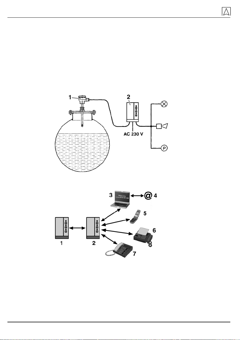
Fig. 1: Schematic overview of the overfill prevention system
1 Level probe 5a Signalling unit
2 Transducer 5b Control unit
4 Signal amplifier 5c Actuator
S Binary signal
3.1 Function
Level probe
The function principle of the level probe is based on the different
heat conductivity of liquid and gaseous fluids. A PTC thermistor at
the tip of the level probe is heated by the probe current of the trans-
ducer. The temperature and thus the electrical resistance of the PTC
thermistor increases in air. If the PTC thermistor is submerged into a
liquid, it cools down and its resistance decreases to almost the initial
value. The probe current is limited so that the PTC thermistor cannot
heat up again while it is submerged. In a gaseous fluid, the heating
up time of the PTC thermistor is between 2 seconds (at an ambient
temperature of +60 °C) and 2 minutes (at an ambient temperature of
-25 °C).
Transducer type NB 220 H
The transducer converts the changes in resistance of the PTC ther-
mistor into relay switching with binary signal output. The relay is de-
energised when the level probe tip has cooled down and also in the
case of power outage as well as a short circuit or wire break in the
connection between the level probe and the transducer. In this case,
the yellow LED at the transducer goes out. A green LED at the
transducer signals that the system is ready to operate.
Transducer type NB 220 QS
The transducer converts the changes in resistance of the PTC ther-
mistor into relay switching with binary signal output. A signal is gen-
erated when the level probe tip has cooled down and also in the

Product description
NB 220 9
case of power outage as well as a short circuit or line interruption in
the connection between the level probe and the transducer. The
transducer provides an audible and a visual alarm when a signal is
generated. The audible signal can be acknowledged by means of the
Acknowledge button. The visual signal remains active (red signal
lamp). When the level probe is no longer submerged, the visual sig-
nal is switched off and the system resumes 'ready' mode. A green
LED at the transducer signals that the system is ready to operate. In
addition, the alarm units mentioned above can also be connected.
Transducer type NB 220 QSA
The transducer converts the changes in resistance of the PTC ther-
mistor into relay switching with binary signal output. The scanner in-
tegrated into the transducer continuously monitors the function of the
PTC thermistor. The characteristic of the PTC thermistor (heating up
and cooling down behaviour) is checked several times per second
and without influencing the ongoing measurement process. This en-
sures immediate detection of a PTC that is no longer operative e.g.
due to external influences (corroded probe sleeve) so that the alarm
unit of the overfill prevention system immediately responds. The en-
ergy supplied to the PTC thermistor is precisely controlled for maxi-
mum reliability and a long service life. A signal is generated when the
level probe tip has cooled down and also in the case of power out-
age as well as a short circuit or line interruption in the connection be-
tween the level probe and the transducer. The transducer provides
an audible and a visual alarm when a signal is generated. The audi-
ble signal can be acknowledged by means of the Acknowledge but-
ton. The visual signal remains active (red signal lamp). Two relay
contacts are provided to make the signal externally available. In the
case of an alarm, one changeover contact is de-energised and one
changeover contact (e.g. for connection of a horn) is energised. After
acknowledgement, this changeover contact is de-energised again;
the second changeover contact remains de-energised. When the
level probe is no longer submerged, the visual signal goes out, the
changeover contact is energised and the system resumes 'ready'
mode. A green LED at the transducer signals that the system is
ready to operate. It is also possible to connect an external
acknowledge button. If the device fuse fails or in the case of power
outage, the green LED "Operation" at the transducer goes out and
the relay contact (changeover contact) is de-energised.
Product description
10 NB 220
3.2 Operating modes
The transducer is equipped with two output relays (1 changeover
contact, 1 normally open contact) to transmit the alarm signal to ex-
ternal devices. In the case of an alarm, the normally open contact is
energised and the changeover contact is de-energised.
The transducer can be operated with or without additional external
devices. External devices include units for audible and visible alarm
signal or remote alarm devices, building control systems, etc.
3.3 Application examples
1 Level probe
2 Transducer
Fig. 2: Overfill prevention system at stationary containers
1 Transducer
2 AFRISO event
reporting system
3 Internet
4 E-mail
5 Mobile phone
6 Fax
7 Telephone
Fig. 3: AFRISO event reporting system for remote reporting

Product description
NB 220 11
Fig. 4: Transducer with mounting frame for panel mounting; right:
panel cut out
3.4 Versions
Table 1: Level probes
Type Version
76 .
.
Without marking -25 °C to +50 °C fluid temperature
H High temperature -25 °C to +80 °C fluid temperature
A Probe tube Ø 16 mm, process connection G¾
E In addition to A: Cable length 3 m (standard)
C In addition to A: Cable length 3 m (standard)
M In addition to A: Cable length 3 m (standard)
N In addition to A: Completely made of stainless steel
for UFS 01 Probe tube Ø 16 mm, process connection G¾, stainless steel,
-25 °C to +50 °C fluid temperature
Table 2: Transducer
Type Version
NB 220 H Visual alarm, one voltage-free changeover contact
NB 220 QS Visual and audible alarm, external connections connected to auxiliary
power
NB 220 QSA Visual and audible alarm, two output relays, external alarm acknowl-
edgement possible
Technical specifications
12 NB 220
4 Technical specifications
4.1 Level probe
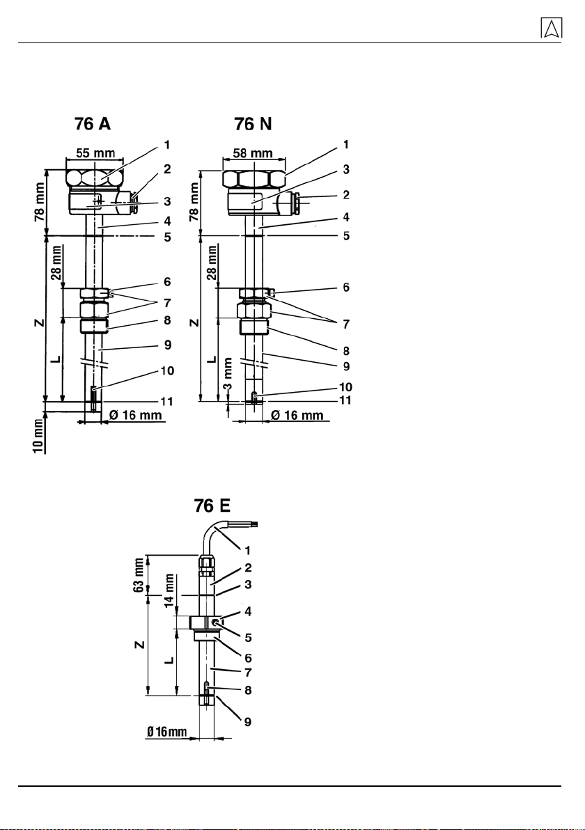
1 SW 52
2 PG 11
3 Nameplate
4 Probe length, embossed
5 Marking groove
6 Locking screw
7 SW 27
8 Screw fitting G¾
9 Probe tube
10 PTC thermistor
11 Response point
L Response length
Z Probe length
Fig. 5: Level probe types 76 A and 76 N
1 Connection cable, 3 m
2 Probe length, embossed
3 Marking groove
4 Screw fitting
5 Locking screw
6 Screw fitting G¾
7 Probe tube
8 PTC thermistor
9 Response point
L Response length
Z Probe length
Fig. 6: Level probe type 76 E

Technical specifications
NB 220 13
1 Cable LiYY 2 x 1 standard
3 m long
2 Probe length, embossed
3 Marking groove
4 Locking screw
5 SW 27
6 Screw fitting G¾
7 Response point
8 Response length em-
bossed
L Response length
Z Probe length
Fig. 7: Level probe type 76 C, 76 M
1 Embossed probe length
2 Marking groove
3 Locking screw
4 O ring
5 Screw fitting G¾
6 Response point
L Response length
Y Check dimension
Z Probe length
Fig. 8: Level probe for UFS 01
Technical specifications
14 NB 220
Table 3: Technical specifications
Parameters for UFS 01 Type 76 ._ Type 76 .H
General specifications
Probe length
(embossed on probe tube) Standard: 100/200/300/400/500 mm
Special versions up to 3000 mm, graduation: 100 mm
Operating temperature range
Medium -25 °C to +50 °C -25 °C to +80 °C
Supply voltage
Nominal voltage Max. DC 13 V
Electrical safety
Degree of protection IP 54 EN 60529
Table 4: Materials (wetted parts)
Component Material
for UFS 01
Probe tube, screw fitting stainless steel 1.4571
O ring Viton
Type 76 A/C
Screw fitting
Seal Brass
Vulkollan
Probe tube
Ring
Sensor holder
O ring
Stainless steel 1.4301-1.4571
Spring steel 1.1248, galvanised
Plastic POM GF 25 %
Elastomer Viton
Type 76 E
Screw fitting
Seal Plastic PE-HD
NBR
Probe tube
Sensor holder
O ring
Stainless steel 1.4301-1.4571
Plastic POM GF 25 %
Viton
Type 76 M
Screw fitting Brass

Technical specifications
NB 220 15
Component Material
Probe tube
Ring
Sensor holder
O ring
Stainless steel 1.4301-1.4571
Spring steel 1.1248, galvanised
Plastic POM GF 25 %
Viton
Type 76 N
Screw fitting
Seal Stainless steel 1.4301-1.4571
Vulkollan
Probe tube/sensor holder (with-
out seal) Stainless steel 1.4301-1.4571
4.2 Dimensional drawings and technical specifications
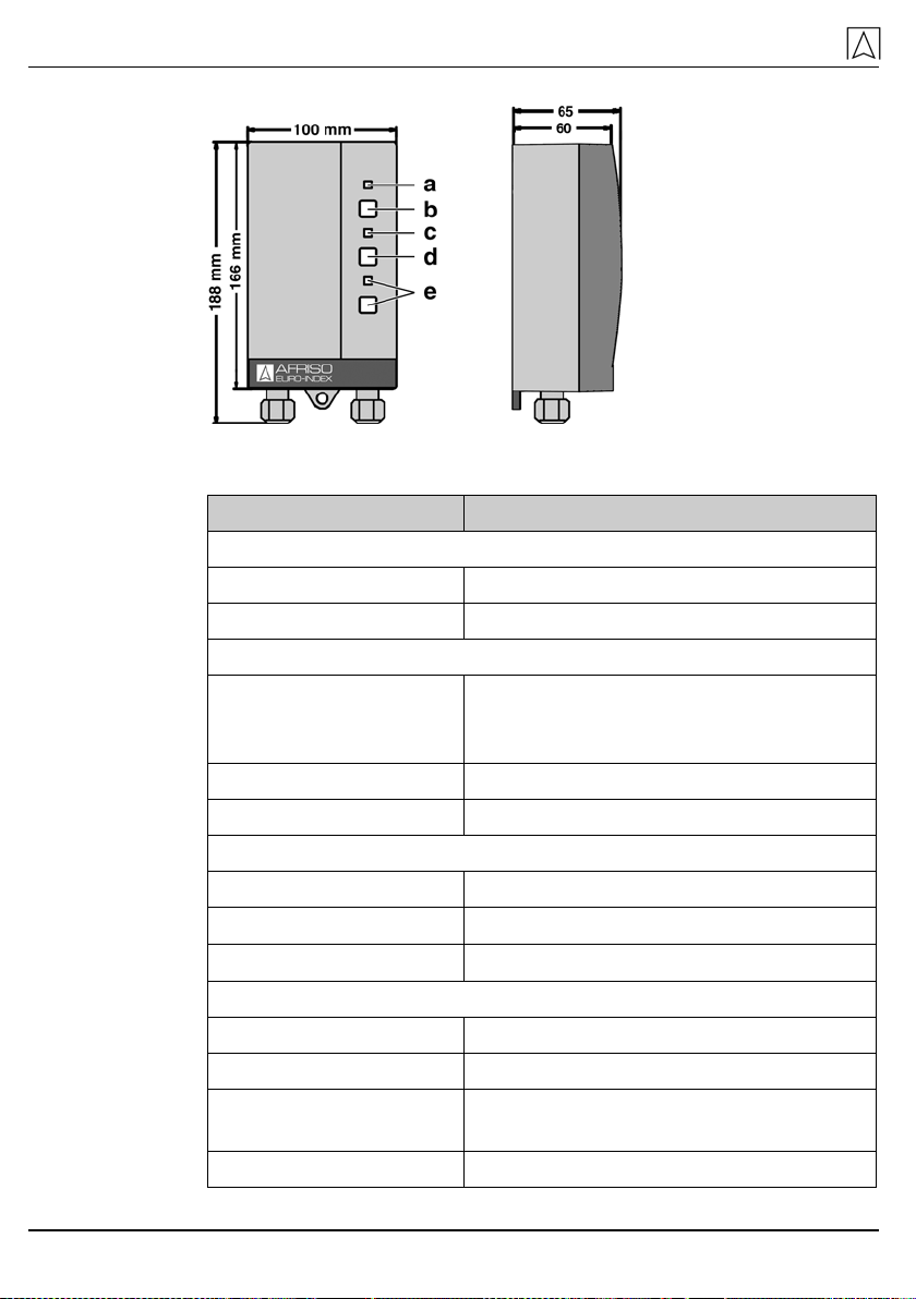
a Probe
b Green pilot lamp
Fig. 9: NB 220 H
a Relay
b Green pilot lamp
c Audible alarm
d Visual alarm and
acknowledge button
Fig. 10: NB 220 QS
Technical specifications
16 NB 220
a Green pilot lamp
b Test button
c Red alarm lamp
d Acknowledge
button
e Without function
Fig. 11: NB 220 QSA
Table 5: Technical specifications transducer
Parameters Value
Operating temperature range
Ambient -20 °C to +60 °C
Storage -25 °C to +60 °C
Supply circuit
Power supply:
NB 220 H, NB 220 QSA
NB 220 QS
24 V, 110 V, 230 V, 50 Hz or DC 24 V
230 V, 50 Hz
Power input Max. 4 VA or 6 W
Mains fuse NB 220 QSA M 32 mA
Output circuit NB 220 H
Outputs 1 voltage-free changeover contact
Alternating voltage ≤250 V; ≤4 A, cos ϕ≥0.7; max. 500 VA
Direct voltage ≤250 V; ≤0.25 A; max. 50 W
Output circuit NB 220 QS
Pump, ampl., etc. 230 V, 50 Hz, max. 50 W
External lamp 230 V, 50 Hz, max. 100 W
External acknowledge
button 230 V, 50 Hz
External horn 230 V, 50 Hz, max. 50 W

Technical specifications
NB 220 17
Parameters Value
Output circuit NB 220 QSA
Outputs 1 voltage-free changeover contact, can-
not be acknowledged, 1 voltage-free
changeover contact, can be acknowl-
edged
Alternating voltage ≤250 V; ≤4 A, cos ϕ≥0.7; max. 500 VA
Direct voltage ≤250 V; ≤0.25 A; max. 50 W
Acknowledgement circuit NB 220 QSA
Voltage ≤12.6 V
Current ≤20 mA
Power ≤60 mW
Cable glands at transducer NB 220 QSA
The centre rubber piece can be replaced
with a cable gland M20.
Cable gland Cable diameter
M16 4.0-8.8 mm
M20 8.0-12.5 mm
4.3 Approvals, tests and conformities
NB 220 has the Technical Approval of the German Institute for Build-
ing Technology with the approval number Z-65.11-193 and complies
with the Construction Products Directive (89/106/EEC), the EMC Di-
rective (2004/108/EC) and the Low Voltage Directive (2006/95/EC).
Transport and storage
18 NB 220
5 Transport and storage
CAUTION
Damage to the device due to improper transport.
Do not throw or drop the device.
Protect from wetness, humidity, dirt and dust.
CAUTION
Damage to the device due to improper storage.
Store the device in a clean and dry environment.
Only store the device within the permissible temperature
range.
Protect from wetness, humidity, dirt and dust.
6 Mounting and commissioning
6.1 Mounting the level probe
Always observe all pertinent national and local safety regula-
tions and all regulations concerning the prevention of accidents
when working on the container.
Choose a mounting position for the level probe that keeps the
overfill prevention system from generating false alarms caused
by splashes of the liquid or by air flow.
If possible, install the level probe vertically so that residual liquid
can drip off of the sensor.
Table 6: Cable lengths of the level probes
Type Cable length
Cable cross section 1 mm² Cable cross section 1.5 mm²
for UFS 01 50 m 100 m
76 .. 500 m 750 m
Type 76 ..: In the case of short connections, you may also use a
smaller cable cross section.
The level probes 76 C, 76 E and 76 M are equipped with a cable end
2 x 1 mm², standard 3 m long. Use a suitable terminal box to connect
the cable.

Mounting and commissioning
NB 220 19
6.2 Adjusting the level probe
1 Embossed probe length Z
2 Marking groove
3 Response point PTC thermis-
tor
A Response level
H Tank height
L Response length
S Connection piece height
Y Check dimension
Z Probe length
Fig. 12: Adjusting the level probe
1. Determine the response height A of the overfill prevention sys-
tem based on the permissible filling level in the tank, using ap-
pendix 1 of the construction and testing principles for overfill
prevention systems.
2. The permissible filling level can be calculated as per TRbF 280
section 2.2. Consider a switching delay of
≤
2 seconds.
3. Calculate response length L as follows:
L = (H – A) + S
For inspection, the response length L can be calculated as fol-
lows without dismounting of the level probe:
L = Z – Y
4. Adjust response length L at the level probe (L = distance be-
tween the hex face of the screw fitting and the response point of
the PTC thermistor).
5. When the level probe is installed, the correct adjustment of the
response height can be checked using the check dimension Y
(Y = distance between marking groove and hex face of the
screw fitting).
6. Tighten the locking screws to lock the probe tube.
7. Screw the screwed thread with the O ring into the existing tank
connection piece.
The response length is embossed in the case of level probes with a
fixed response length. The response length is the distance between
the hex face and the marking groove at the protective sleeve of the
sensor at the lower end of the level probe.
Mounting and commissioning
20 NB 220
Level probe with screw fitting 76 ...
1. Determine the response length on the basis of the tank data and
adjust it.
2. Tighten the upper compression gland screw and the locking
screw of the screw fitting to lock the probe tube.
3. Apply suitable, resistant sealing material to the screwed connec-
tion thread and screw it into the existing tank connection piece.
Level sensor with fixed screw fitting 76 M
1. Since the response length of the level probe is not variable
(probe tube and screw fitting are permanently connected), you
must determine the exact length on the basis of the tank dimen-
sions and specify it when ordering.
2. Apply suitable, resistant sealing material to the screwed connec-
tion thread and screw it into the existing tank connection piece.
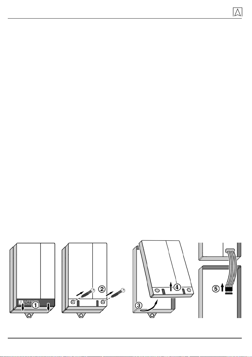
6.3 Mounting the transducer
Mount the transducer to an even, rigid and dry wall at eye level.
The transducer must be accessible and easy to oversee at all
times.
The transducer must not be exposed to water or splash water.
Do not mount the transducer in damp rooms.
The maximum ambient temperature at the transducer must not
be exceeded.
In the case of outdoor installation, protect the transducer from
direct atmospheric influences and mount it into an additional
housing with degree of protection IP 54 or higher.
1. Open the transducer.
Table of contents
Other Afriso EURO-INDEX Security Sensor manuals


