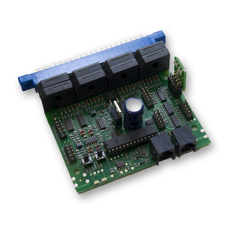
Digitrax BDL16 Service manual

1
1.0 Introduction 2
2.0 Terminology 2
3.0 Track Wiring for Detection with BDL16 4
4.0 BDL16 Installation 4
5.0 Set up for Non-Digitrax layouts 8
6.0 Customizing Your BDL16 By Setting Up Option Switches 10
6.1 How to read back and change BDL16 Option Switches: 10
7.0 Power Management 11
8.0 Auto-Reversing 13
9.0 LED Occupancy Indicators 13
10.0 BDL16 Board Address 14
10.1 To set up the board address 14
11.0 Troubleshooting: Checklist 14
11.1 Packet Reception 14
11.2 Mode Indication 15
11.3 Occupancy Debug 15
11.4 LocoNet Debug 15
11.5 Analog Locomotives 15
12.0 Warranty and Repair Information 16
13.0 FCC Information 16
BDL16 LocoNet Occupancy Detector
with RX4 Installation Information
Manual
Digitrax, LocoNet, Genesis II, Empire Builder II, Chief II, Super Chief, and
others included in this manual are trademarks of various manufacturers includ-
ing Digitrax and others. There are many different manufacturers who build
products that work with Digitrax, those used in this manual are for example
only. U.S. & International Patents Pending for BDL16, RX4, transponding and
other Digitrax products & technologies
Copyright Digitrax, Inc. All rights reserved. Printed in USA. REV 02/01

Security element is the plant, including track, associated with any reporting,
interlocking and/or signaling for that track section.
Whole layout common rail is a method of wiring layouts where power dis-
tricts and their boosters are connected electrically by a common rail or com-
mon power bus return wire. This method is traditionally used for convention-
ally controlled layouts. The track feeds for one rail are connected together to
one output of the power pack. The other rail is gapped and the track feeds are
connected to the power pack through block control switches. Whole layout
common rail wiring has a disadvantage when it comes to detection systems
because detectors are not able to independently monitor whether zone power is
on or off. There is no way to tell whether occupancy detection is actually
working in any given detection section.
Detection Section is a section of track gapped on one or both rails and con-
nected to an occupancy detector so that the detector can sense the presence of a
loco (or other specially equipped cars) in that section of track.
Occupancy detector is a device that senses the presence of a locomotive (or
other specially equipped cars) in a section of track that is set up for occupancy
detection. Occupancy detectors also provide feedback to indicate occupancy.
This feedback may be in the form of a lamp on a control panel or it may be a
feedback message sent to the system that can be used by other layout devices.
Also called a block occupancy detector on conventional layouts. Detectors are
not covered by the DCC Standards or Recommended Practices.
Transponder is an electronic device with a transponder address that is
installed in rolling stock. Transponders provide information to transponder
detectors installed on the layout. This lets the system determine in which
detection section the transponder is currently located. Transponders are includ-
ed in many Digitrax premium decoders. TD1 (transponder) & TL1 (transpon-
der with light output) are available as separate units that can be added to locos
with existing decoders or to other rolling stock without decoders if you want to
use them for transponding only and don't need motor control.
Transponder detector is an electronic device installed in a detection section
on the layout that receives the information broadcast from a transponder. The
transponder detector sends feedback to the system that lets it determine the
detection section location of any given transponder at any time. RX4
Transponder detectors are hosted by the BDL16 and upgrade 4 detection zones
of the BDL16 to be transponder detection zones. In this case, each transpond-
ing zone encompasses 4 detection zones.
The BDL16 is divided into four Zones. Each Zone supports 4 detection sec-
tions and each zone can be run from a different booster.
3
1.0 Introduction
The BDL16 uses digital signal processing (DSP) to give you occupancy detec-
tion for 16 detection sections on your layout. The BDL16 can also host
transponder detectors to let you implement Digitrax transponding. The BDL16
reports detection section occupancy and transponder location information to the
system via its LocoNet connection. You can also install LEDs in an occupancy
display panel to report detection section occupancy and transponder location.
The BDL16 is split into 4 zones, A through D, each with 4 detection sections,
for a total of 16 detection sections. Each BDL16 zone can be run from a dif-
ferent booster.
On your Digitrax system, the BDL16 automatically detects the LocoNet con-
figuration it finds and initializes itself accordingly. This automatic detection
also lets BDL16’s be used for occupancy detection on DCC systems without a
Digitrax compatible LocoNet command station.
The BDL16 can operate with no connection to LocoNet, using only the
RailSync DCC signal from any Digitrax compatible DCC system, and report-
ing detection information via optional LED outputs.
2.0 Terminology
Following are some terms you might find useful as you work with the BDL16.
Direct home wiring is a layout wiring method where each power district and
its booster is electrically isolated. The track within each power district uses a
"common return" wiring method for occupancy detection and/or power man-
agement. Direct home wiring is the wiring method recommended by Digitrax
for safety reasons & also because it makes detection work more prototypically.
Power district is the power wiring, components and equipment attached to that
wiring, driven by a single properly isolated booster. Power districts are double
gapped on both ends. BDL16 is used to set up detection sections within one or
more power districts.
Power sub-district is the wiring, components and equipment that are con-
trolled from both power bus wires by their own power management device, for
example a reversing section controlled by an automated reversing device like
the PM4. Power sub-districts are gapped on both ends.
Detection common is the common return used within a properly electrically
isolated power district for implementing occupancy detection.
2

5
3.0 Track Wiring for Detection with BDL16
BDL16 comes from the factory set up for DCC operation on layouts that use
direct home wiring. Direct home wiring is the wiring method recommended by
Digitrax. With direct home wiring, each power district and its booster is elec-
trically isolated. This method of wiring has safety advantages and makes detec-
tion work more prototypically. The track within each power district can use
"common rail" wiring for detection or power management. In most cases, the
BDL16 will work as it comes from the factory with direct home wiring when
its 44 pin socket is wired to the layout and connections are made to a 12V AC
power supply (100mA minimum), booster power and ground. Figure 1:
Typical Direct Home Wiring, shows the typical usage of a BDL16 operating
all 4 zones from a single booster, i.e. in a single power district. A single
BDL16 can be operated by up to four different boosters.
With direct home wiring, the BDL16 can determine & indicate whether any of
its 4 zones is powered or not (possibly short-circuited) even when there is noth-
ing on the rails in the detection sections. The BDL16 default logic causes the
detection sections to show "occupied" if the associated zone's power is off
(because in this case, detection is not possible). This default matches prototype
detection safety practices.
Whole layout common rail is a method of wiring layouts where power districts
and their boosters are electrically connected using a common rail or common
power bus return wire. Whole layout common rail wiring is at a disadvantage
when it comes to detection systems since detectors cannot independently moni-
tor whether zone power is on or off so they can't tell whether occupancy detec-
tion is working or not in any given detection section. To get around this limita-
tion, the BDL16 uses option switch 10 to set up detection section 16 to be used
as a zone power detector for detection sections 1 through 15. Wire a 10K resis-
tor from detection section 16 (not connected to tracks) to the detection common
return for the whole BDL16. Then detection section 16 on the BDL16 will be
active when the BDL16 sees track power and you will be able to tell whether
detection is actually available in detection sections 1 through 15.
4.0 BDL16 Installation
TABLE I shows the pin-out for the BDL16's 44 pin connector. Be sure to wire
the BDL16 ground wire to the Digitrax Booster ground, common (or case) of
the boosters. Wire the track outputs to the appropriate detection section follow-
ing the example in Figure 1. The Zone common connections to the booster
should be as short as possible and relatively heavy gauge, since they are com-
mon to all four detectors in the zone. For example, a 12awg zone connection to
the booster should be less than 10 feet for best performance. For whole layout
4
12345678910111213141516171819202122
TOP ROW
AB
C
D
AUX1
AUX2
PS12
12 VAC
Power
Supply
Zone Common
(Heavy Wire)
Detection Common
Booster Ground to pin 11
Zone A
DS 1
DS 2
DS 3
DS 4
Zone B
DS 5
DS 6
DS 7
DS 8
Zone C
DS 9
DS 10
DS 11
DS 12
Zone D
DS 13
DS 14
DS 15
DS 16
Booster GND
Ext. Power
BDL16
Top View
Detection Section
1Detection Section
2Detection Section
3Detection Section
4
TRACK
STATUS
POWER
ON
OFF LINE
O/G
N
HO
MODE
MODE
O
RUN
LOCONET
A B
SCALE
SLEEP
SLEEPP
P
R
R
RAIL B
POWER INPOWER IN
RAIL A
POWER INPOWER IN
GROUND
LocoNet
to other LocoNet
Devices such as
(Throttles, Boosters,
UP3's Etc.)
12 VAC to Pin 12
12 VAC to Pin N
Note: BDL16 Zone A Wiring
shown for clarity. Zones B, C,
and D are wired similarly.
External LED
Connectors (pin 1)
(See
Figure 4)
Figure 1: Typical Direct Home Wiring
Direct Home Booster (Digitrax standard)
ID LED (green)
Option LED (red)
Detection Section
16
~
~~
~

7
6
Pin
#
Name
Connect To
1
Zone A
Connection to booster for Zone A
2
Detection
Section 1
(DS 1)
Isolated track section for Detection Section 1
3
DS 2
Isolated track section for Detection Section 2
4
DS 3
Isolated track section for Detection Section 3
5
DS 4
Isolated track section for Detection Section 4
6
Zone B
Connection to booster for Zone B
7
DS 5
Isolated track section for Detection Section 5
8
DS 6
Isolated track section for Detection Section 6
9
DS 7
Isolated track section for Detection Sectio n 7
10
DS 8
Isolated track section for Detection Section 8
11
Ground**
LocoNet/BDL16 ground to Booster
case/common ground
12
AC Power 1*
Power input to BDL16 : AC 12V to 15V, or
+DC 12V to 15V
13
Zone C
Connection to booster for Zone C
14
DS 9
Isolated track section for Detection Section 9
15
DS 10
Isolated track section for Detection Section 10
16
DS 11
Isolated track section for Detection Section 11
17
DS 12
Isolated track section for Detection Section 12
18
Zone D
Connection to booster for Zone D
19
DS 13
Isolated track section for Detection Section 13
20
DS 14
Isolated track section for Detection Section 14
21
DS 15
Isolated track section for Detection Section 15
22
DS 16
Isolated track section for Detection Section 16
Pin
#
Name
Connect To
A
Zone A
Connection to booster for Zone A
B
Detection
Section 1
Isolated track section for Detection Section 1
C
DS 2
Isolated track section for Detection Section 2
D
DS 3
Isolated track section for Detection Section 3
E
DS 4
Isolated track section for Detection Section 4
F
Zone B
Connection to booster for Zone B
H
DS 5
Isolated track section for Detection Section 5
J
DS 6
Isolated track section for Detection Section 6
K
DS 7
Isolated track section for Detection Section 7
L
DS 8
Isolated track section for Detection Section 8
M
LocoNet
LocoNet network, connect to RED/GREEN
wires if not using RJ12 jacks
N
AC Power 2*
Power input to BDL16: AC 12V to 15V, or
DC 12V to 15V return
P
Zone C
Connection to booster for Zone C
R
DS 9
Isolated track section for Detection Section 9
S
DS 10
Isolated track section for Detection Section 10
T
DS 11
Isolated track section for Detection Section 11
U
DS 12
Isolated track section for Detection Section 12
V
Zone D
Connection to booster for Z one D
W
DS 13
Isolated track section for Detection Section 13
X
DS 14
Isolated track section for Detection Section 14
Y
DS 15
Isolated track section for Detection Section 15
Z
DS 16
Isolated track section for Detection Section 16
TABLE I: BDL 16 Connector Printed Circuit Bboard Component Side TABLE I: BDL 16 Connector Printed Circuit Board Solder Side
Note that all connector pins except 11/M and 12/N are paired top (com-
ponent side) and bottom(solder side) of the PCB(printed circuit board).
For 6A current rating with 3A connector pins, track/zone wires must be
connected to both pin pairs: e.g., Zone A = pins 1 & A.
Note some letters are not used on connector.
*These AC1/AC2 power connections should be made to supply only used by
BDL16(s).
**The Ground connection must be made to booster for correct BDL16 opera-
tion.

9
common rail wiring, refer to Figure 2:Common Rail Wiring and be sure to
change option switch 10 to "closed".
If you are using a Digitrax system, connect LocoNet via one of the BDL16's
LocoNet jacks. If you are using another DCC system, connect the leftmost pin
of the RJ12 socket (called the RailSync pin) to a reliable source of the DCC
signal that matches the DCC signal being sent by the booster to the detection
sections handled by the BDL16. It is best if this signal stays active even when
the booster output is shorted or disconnected from the BDL16 zone inputs, for
example by a PM4 Power Manager.
Connect a 12VAC power supply to the AC1 and AC2 terminals of the BDL16's
44 pin connector. This powers the BDL16(s). Multiple BDL16 units can be
supplied by a single shared supply as long as you provide at least 100mA for
each BDL16. This supply should not power or be shared by any devices other
than BDL16’s.
Set up the BDL16 to operate on your layout: The BDL16's option switches are
set at the factory for default values that will work for most direct home wired
layouts. You can fine-tune the BDL16's characteristics using its option switch-
es. The BDL16's option switches can be set using a Digitrax compatible throt-
tle or a PC with LocoNet compatible software that can control turnouts. See
"Customizing your BDL16 By Setting Up Option Switches below".
5.0 Set up for Non-Digitrax layouts
To make set up simpler and to make it easier for non-Digitrax layouts to use
the BDL16, there are two quick configuration buttons that let you set up your
unit to work with either direct home or whole layout common rail without
using a Digitrax throttle or computer.
If the “ID” switch behind the green ID LED is held down when AC power is
first applied, the BDL16 will operate on direct home layouts(the default as
shipped from factory). When DCC packets are supplied to the RJ12 connector
the ID LED will be lit and “wink” off once every 2 seconds to indicate direct
home operation is selected.
If the “OPTION” switch behind the red option LED is held down when AC
power is first applied, the BDL16 will operate on whole layout common rail
layouts. When DCC packets are supplied to the RJ12 connector the ID LED
will be lit and “wink” off twice every 2 seconds to indicate whole layout com-
mon rail operation is selected.
If either switch is pressed when the BDL16 is first powered up, the BDL16
will be re-configured.
8
12345678910111213141516171819202122
TOP ROW
AB
C
D
AUX1
AUX2
PS12
12 VAC
Power
Supply
Common
Rail Return
Detection Common
Booster Ground
to pin 11
Zone A
DS 1
DS 2
DS 3
DS 4
Zone B
DS 5
DS 6
DS 7
DS 8
Zone C
DS 9
DS 10
DS 11
DS 12
Zone D
DS 13
DS 14
DS 15
DS 16
Booster GND
Ext. Power
BDL16
Top View
Detection Section
1Detection Section
2Detection Section
3Detection Section
15
TRACK
STATUS
POWER
ON
OFF LINE
O/G
N
HO
MODE
MODE
O
RUN
LOCONET
A B
SCALE
SLEEP
SLEEPP
P
R
RAIL B
POWER INPOWER IN
RAIL A
POWER INPOWER IN
GROUND
LocoNet
to other LocoNet
Devices such as
(Throttles, Boosters,
UP3's Etc.)
12 VAC to Pin 12
12 VAC to Pin N
External LED
Connectors (pin 1)
See Fig. 4
Figure 2: Common RailWiring
Opto-Isolated Booster
DS 16 Used as
Zone Power Detector
For Zones 1 thru 15
To other Common Rail
Sections
To other
Common Rail
Sections
Track Detection
uses the Layout
Common Rail
ID LED (green)
Option LED (red)
(Heavy Wire)
Digitrax Special Order or
Other Digitrax Compatible Booster
~
~~
~
10 kohm
Resistor
Note: For this example,
BDL16 OPSW 10 must
be set to "c".

7.0 Power Management
The BDL16 is designed to operate “downstream” of the Digitrax boosters and
power management devices. The BDL16 is the "last" device in the chain from
booster to power manager to BDL16. It is connected directly to the track
detection section. There should be no other connections to any detection sec-
tion that will draw track power or the detection section will always show occu-
pied.
If a device is used to switch off power feeding the BDL16 and the track it is
connected to, for example, a PM4 Power Manager, it should break the track
power to both the zone and detection common rail. If a device only switches
off a single leg, then it must be placed in the detection common rail wiring.
11
6.0 Customizing Your BDL16 By Setting Up Option
Switches
TABLE II, below, details the option switches & settings you can use to cus-
tomize your BDL16. These option switches are set up using your Digitrax
throttle's SWITCH commands. SWITCH mode is normally used for operating
turnouts by issuing closed ("c") or thrown ("t") commands. In the case of your
BDL16, each switch address is a BDL16 option switch.
6.1 How to read back and change BDL16 Option Switches:
1. Power up your BDL16.
2. Press the switch behind the red option LED for about 1 second, then release
it. The red option and green ID LEDs will flash alternately to let you know
that you are in option switch setup mode.
3. Connect a DT or UT series Digitrax throttle to the BDL16's LocoNet con-
nector.
4. Go into SWITCH mode. Dial up the switch number that corresponds to the
OPSW you want to change and issue a closed "c" or thrown "t" command to
set the OPSW to the desired setting. The OPSW is changed as soon as you
issue the SWITCH command. See below for instructions for specific Digitrax
throttles.
5. When BDL16 OPSWs are set up as desired, press the switch behind the red
option LED for about 1 second and release it, the BDL16 will exit option
switch set up mode. You can also exit option switch set up mode by turning
off the power to the BDL16 and then turning it back on.
DT100 or DT200 series throttle, press “MODE/DISP” on the throttle to enter
SWITCH mode. Use the throttle to read back each OPSW in TABLE II by
dialing it up on the throttle and looking at it's setting (c or t). If you need to
make a change to the OPSW simply press c or t to make the change you want.
Once you are finished reading back and changing settings, simply wait 6 sec-
onds for the throttle to time out and return to LOCO mode. Be sure to com-
plete step 5 above when finished setting OPSWs.
UT series throttle, press RUN/STOP and DISP/OPSW at the same time to
enter SWITCH mode. With a UT throttle, you won't be able to read back the
BDL16 OPSW settings but you can change them by dialing up the OPSW
number you want to modify and pressing the c key. When the LED under the c
key is on the OPSW is set to closed, when it is off, the OPSW is set to thrown
(the factory default setting). When you are finished setting up BDL16 OPSWs,
return to LOCO mode by pressing RUN/STOP and DISP/OPSW at the same
time to exit SWITCH mode. Be sure to complete step 5 above when finished
setting OPSWs.
10
OPSW
t=thrown (factory default)
c=closed
01
Set up for operation with
direct home wired layouts
(Digitrax recommended
wiring)
Set up for whole layout
common rail wired layouts
09
Detection sections show
occupied when zone power
is off
no forced occupied
detection when zone power
is off
10
Use detection section 16 as
a normal detection section.
Use detection section 16 as
zone power ON qualifier
for whole layout common
rail wiring
11
Allow this BDL16 to be the
master.
Do not allow this BDL16
to be master
12
Allow this BDL16 to
terminate LocoNet
Do not allow this BDL16
to terminate LocoNet
13
Power up delay 5 seconds
for DB150 compatibility
Power up delay 1/2 second
19
Use regular threshold sense
DCC occupancy. (approx 22
kohms minimum)
Use high threshold sense
DCC occupancy (approx
10 kohms minimum)
25
16 LEDs show occupancy
Drive 16 occupancy LEDs
from SWITCH commands
(not occupancy)
26
Occupancy LEDs decoded
from track DCC switch
commands
Occupancy LEDs decoded
from LocoNet SWITCH
commands
40
Direct home wiring
compatible
Make all option switches
factory default
TABLE II: BDL16 Option Switches (OPSWs)
BDL16 option switches (OPSWs) have a default of “t” or thrown. The
following table shows what each OPSW is used for when it is set for
thrown or closed.

8.0 Auto-Reversing
Note that an auto-reverse section can only use detection sections that are con-
tained in a BDL16 zone that is correctly set up for auto-reversing , see Figure
3: Reverse Section Wiring for a wiring example.
9.0 LED Occupancy Indicators
9.1 LT5 Tester
Each BDL16 comes with an LT5 that will help you with layout wiring and
troubleshooting for transponding & detection with Digitrax BDL16 LocoNet
Occupancy Detector. The LT5 plugs onto the LED Connections of BDL16 and
the LEDS on the LT5 light when detection sections are occupied. The status of
power to each zone is also shown.
9.2 Panel Indicator Wiring
For a front panel display of status with user supplied LED’s, connect to the
four 0.1” 2x5 headers, and wire up LEDs as shown in Figure 4: LED Panel
Indicators Wiring. DigiKey (1-800-DigiKey) part number M1AXA-1036R-
ND is a convenient plug and cable assembly that you can use to wire LED
indicators. Header “A” includes the 4 detection indicators for detection sec-
tions 1 to 4 and the zone power indicator for zone A that includes these four
12345678910
AB
C
D
Zone A
DS 1
DS 2
DS 3
DS 4
Zone B
DS 5
DS 6
DS 7
DS 8
BDL16 (PartialTop View)
LED for First Detection Section (1,5,9, or 13)
LED for Second Detection Section (2,6, 0, or 14)
LED for Third Detection Section (3,7,11, or 15)
LED for Fourth Detection Section (4,8,12, or 16)
LED for Power Zone (A, B, C, or D)
Socket
Plug LT5 Tester in to External LED Connectors A,B,C, or D
with LED's facing the edge of the BDL16 as shown.
LT5Tester
External LED
Connectors
LocoNet
Connectors
LT5Tester
13
12
12345678910111213141516171819202122
TOP ROW
AB
C
D
AUX1
AUX2
PS12
12 VAC
Power
Supply
Zone A
DS 1
DS 2
DS 3
DS 4
Zone B
DS 5
DS 6
DS 7
DS 8
Zone C
DS 9
DS 10
DS 11
DS 12
Zone D
DS 13
DS 14
DS 15
DS 16
Booster GND
Ext. Power
BDL16
Top View
LocoNet
to other LocoNet
Devices such as
(Throttles, Boosters,
UP3's Etc.)
12 VAC to Pin 12
12 VAC to Pin N
External LED
Connectors (pin 1)
See Fig. 4
Figure 3: Reverse Section Wiring
ID LED (green)
Option LED (red)
These 2 wires come
from a reversing device
such as a PM4 Reverse
Section, a separate
auto-reversing booster,
a DPDT toggle switch,
or other reversing
device.
Zone Common
Detection Common
Booster Ground to pin 11
For non-reversing
Detection Sections
For non-reversing Detection
Sections
All 4 Detection Sections
in this zone can only be
used in this
reverse section
Reverse
Section Non-reversing
part of layout
{
Using 4
Detection Sections

address. The board address is changed as soon as you issue the SWITCH com-
mand. See below for instructions for specific Digitrax throttles.
DT100 or DT200 series throttle, press “MODE/DISP” on the throttle to enter
SWITCH mode. Use the throttle dial up the board address you would like to
assign to the BDL16. When the address is in the display, press "c" to issue a
closed command. This will set the board address for the BDL16. The green
LED will then go steady green to indicate BDL16 Power on.
UT series throttle, press RUN/STOP and DISP/OPSW at the same time to
enter SWITCH mode. With a UT throttle, dial up the board address you would
like to assign to the BDL16. Press the "c" key until the corresponding LED is
lit. This will set the board address for the BDL16. The green LED will then go
steady green to indicate BDL16 Power ON. When you are finished setting up
BDL16's board address, return to LOCO mode by pressing RUN/STOP and
DISP/OPSW at the same time to exit SWITCH mode.
11.0 Troubleshooting: Checklist
11.1 Packet Reception
Be sure the green ID LED is ON & is “winking” off about every 2 seconds.
This means that correctly formatted DCC packets are being decoded from the
left most (Railsync) pin of the RJ12 LocoNet socket. For DCC detection, the
same DCC packet signal that drives the booster must be connected to the RJ12
socket's leftmost pin. If you are using LocoNet, and you do not see the green
LED blinking pattern described, check to be sure that the system is powered up
and that your LocoNet cable connections are good. You can use your LT-1 to
test the LocoNet cables if you suspect there is a problem with them. If the
green LED on the BDL16 is not lit, check the external power connections.
11.2 Mode Indication
The winking on the green ID LED indicates the primary BDL16 mode. A sin-
gle wink indicates standard Digitrax compatible Direct Home track wiring and
detection logic will be used, a double wink indicates Common Rail wiring and
detection logic is to be used. For Common Rail, all 4 BDL16 zone connections
must be made to the System Common ground point. Be sure the BDL16 con-
figuration is appropriate for your usage.
11.3 Occupancy Debug
Use the LT5 provided with your BDL16 as described in Section 9.1. You can
also build a simple LED display debugger as follows. Use a 10 pin plug and
cable such as DigiKey (1-800-DigiKey) part number M1AXA-1036R-ND that
will plug into one of the 4 occupancy LED headers on the BDL16 and solder
LEDs to the wires to create an array of LEDs. By plugging this display array
15
detection sections.
The BDL16 incorporates current setting resistors to set the LED current typi-
cally about 3mA. If you use higher LED drive currents you can external tran-
sistors etc to amplify the LED current.
The LED drive from the BDL16 is active high at about +5 volts above the
BDL16 ground pin, via a 1 kilo-ohm resistor. Note that the ribbon cable
includes separate ground return conductors for each LED that allow a 10 con-
ductor ribbon cable to be split into 5 pairs to conveniently route to individual
LEDS. Be sure to connect the +ve active output leads to the LED anodes.
10.0 BDL16 Board Address
When the BDL16 is connected to LocoNet, it will communicate coded detec-
tion information to the system. If you wish to report BDL16 status to LocoNet
and attached devices or computers that can interpret these messages, you will
probably want to set up a unique board address for each BDL16.
10.1 To set up the board address
1. Power up your BDL16.
2. Press the switch behind the green ID LED for about 1 second, then release
it. The green ID LED will blink. The red option LED will not light. This let's
you know that you are in board address set up mode.
3. Connect a DT or UT series Digitrax throttle to the BDL16's LocoNet con-
nector.
4. Go into SWITCH mode. Dial up the switch number that corresponds to the
board address you want to set and issue a closed "c" command to set the board
Figure 4: LED Panel IndicatorsWiring
Pin 1
GND
GND
GND
GND
GND
Detection Section
1, 5, 9, 13
Detection Section
2, 6, 10, 14
Detection Section
3, 7, 11, 15
Detection Section
4, 8, 12, 16
Zone A, B, C, D
Power
Front Panel LEDs
External LED
Connector
Ribbon Cable & Plug
(DigiKey #M1AXA-1036R-ND)
Edge of PC Board
Note: Connect active output leads to LED anode
& ground leads to LED cathode.
14

dance with the manufacturer's specifications, any and all warranties either
expressed or implied are void. Except to the extent expressly stated in this
section, there are no warranties, express or implied, including but not lim-
ited to any warranties of merchantability or fitness for a particular purpose.
Digitrax, Inc. reserves the right to make changes in design and specifi-
cations and/or to make additions or improvements in its products without
imposing any obligations upon itself to install these changes, additions or
improvements on products previously manufactured.
13.0 FCC Information
Radio or TV Interference: (this information is MANDATED by the FCC) This equip-
ment has been tested and found to comply with the limits for a Class B digital device,
pursuant to part 15 of the FCC rules. These limits are designed to provide reasonable
protection against harmful interference when the equipment is operated in a residential
environment. This equipment generates, uses and can radiate radio frequency energy
and, if not installed and used in accordance with the instruction manual, may cause
harmful interference to radio communications. However, there is no guarantee that inter-
ference will not occur in a particular installation. If this equipment does cause harmful
interference to radio or television reception, which can be determined by turning the
equipment off and on, the user is encouraged to try to correct the interference by one or
more of the following measures:
-Reorient or relocate the receiving antenna.
-Increase the separation between the equipment and the receiver.
-Connect the equipment into an outlet on a circuit different form that
to which the receiver is connected.
-Consult the dealer or an experienced radio/TV technician for help.
Note that any modifications to the equipment not expressly approved by Digitrax voids
the user's authority to operate under and be in compliance with CFR 47 rules, as
administered by the Federal Communication Commission. Digitrax believes any
conscientiously installed equipment following guidelines in this manual would be
unlikely to experience RFI problems.
17
into one of the 4 occupancy LED headers, you can see the state of the zone and
occupancies for that header. This allows you to easily check the zone sensitivi-
ty (typically 22K ohms to give detection). This also aids in the determination
of detection number and activity for a track detection section. Many detection
problems are related to wiring problems or poor connections to the detection
section rather than to the actual BDL16. By using the display array, you can
eliminate the wiring issues from the equation and be sure that the BDL 16 is
set up correctly.
Remember, if the zone power is OFF, the occupancy LEDs should be set up so
that they will be on to be sure that signaling systems or a CTC/dispatcher will
see the detection section in its most restricted aspect.
11.4 LocoNet Debug
If you are using LocoNet for reporting, be sure that the configuration is correct
for your usage. In normal operations the red “option” LED will blink ON
briefly when valid LocoNet messages are seen confirming a good LocoNet net-
work connection.
11.5 Analog Locomotives
The motor inductance of analog locomotives may in some installations cause
cross talk among the BDL16 detection sections. The addition of a 220ohm
3watt power wire wound resistor between the booster track terminals (Rail A
and Rail B on Digitrax boosters) will typically reduce the effect of this cross
talk. Simply use a leaded resistor as a jumper between the booster's two track
terminals.
12.0 Warranty and Repair Information
Digitrax guarantees the BDL16 to be free from manufacturing defects
for five years from the date of purchase. These units are not user service-
able. If a defect occurs, return the unit to Digitrax for service. Digitrax
will repair or replace BDL16s at our discretion at no charge to you for one
year from purchase date. This warranty excludes damage due to abuse,
such as failure to properly protect against input over current with a fuse or
circuit breaker or applying excessive input voltage to the unit.
Digitrax will make non-warranty repairs needed because of physical
damage or electrical abuse at fair and reasonable rates.
All warranties on Digitrax products are limited to refund of purchase
price or repair or replacement of Digitrax products at the sole discretion of
Digitrax.
In the event that Digitrax products are not installed or used in accor-
16
Table of contents
Other Digitrax Security Sensor manuals
Popular Security Sensor manuals by other brands
Aparton
Aparton SPT-3B user manual
SATO
SATO S110TRH-10 instruction manual
MD
MD mXion RBM user manual
Honeywell
Honeywell Ex-Or MR2500D Installation and commissioning instructions
STIF
STIF VIGIBELT TOUCH instruction manual
Niko
Niko Swiss Garde 360 DALI Secondary A-Comfort high ceiling... installation instructions
