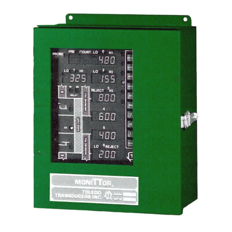
Toledo Transducers PressWatch LS-ZT Series User manual

LS-ZT User’s Manual - Installation
DOC #18445 Page
Toledo Integrated Systems
1
PressWatch
Load Signature ZT Series
Load Monitor
User’s Manual
Revision: A

LS-ZT User’s Manual - Installation
DOC #18445 Page
Toledo Integrated Systems
2
Table of Contents
Limited Warranty..................................................................................................................4
Features Overview ................................................................................................................5
Specifications........................................................................................................................7
Installation ...........................................................................................................................9
Mounting the LS-ZT ...........................................................................................................9
LS-ZT Components...........................................................................................................10
Conduit Hole Selection.....................................................................................................11
AC Power Requirement and Connection ............................................................................12
Tonnage Sensor Connection .............................................................................................13
Resolver Connection........................................................................................................17
Resolver Input Setup........................................................................................................19
Shutdown (Stop) Relays ...................................................................................................22
Serial Port Connection .....................................................................................................23
Operation...........................................................................................................................25
Overview ........................................................................................................................25
Initial Startup ..................................................................................................................26
Main Window .................................................................................................................27
Tonnage .........................................................................................................................29
Signatures.......................................................................................................................32
Statistics.........................................................................................................................35
Setpoints ........................................................................................................................36
Configure........................................................................................................................40
Calibration ..................................................................................................................60
Job Settings.....................................................................................................................62
External Configuration Files ..............................................................................................66
Live Data Output Feature .................................................................................................69
Calibration Procedure..........................................................................................................71
Operator’s Guide ................................................................................................................81
Appendix............................................................................................................................83
A) Sensor Installation (Doc# 11080).............................................................................83
B) Calibration Sheets (2) (Form# 1224)........................................................................83
Table of Figures
Figure 1-1: Mounting Dimensions.........................................................................................9
Figure 1-2: LS-ZT Components............................................................................................10
Figure 1-3: Conduit Hole Selection......................................................................................11
Figure 1-4: AC Power Wiring ..............................................................................................12
Figure 1-5: Tonnage Sensor Input.......................................................................................14
Figure 1-6: Tonnage Sensor Cable Stripping.........................................................................15

LS-ZT User’s Manual - Installation
DOC #18445 Page
Toledo Integrated Systems
3
Figure 1-7: Tonnage Sensor Wiring..................................................................................... 16
Figure 1-8: Resolver Input Descriptions .............................................................................. 17
Figure 1-9: Resolver Wiring................................................................................................. 18
Figure 1-10: Resolver Setup ................................................................................................ 19
Figure 1-11: Shutdown Relay Wiring .................................................................................... 22
Figure 1-12: Serial Port Connection...................................................................................... 23
Figure 1-13: Serial PressNet Connection............................................................................... 24
Figure 2-1: System Overview ............................................................................................. 25
Figure 2-2: Communication Error Alert ............................................................................... 26
Figure 2-3: Communication Error (Historical Data Box)......................................................... 26
Figure 2-4: SlimWare Main Window................................................................................... 27
Figure 2-5: Tonnage Screen (4-Channel) ............................................................................. 29
Figure 2-6: Signature Screen (4-Channel) ............................................................................ 32
Figure 2-7: Statistics Screen............................................................................................... 35
Figure 2-8: Standard Setpoints Screen (4-Channel) .............................................................. 36
Figure 2-9: Envelope Setpoints Screen (4-Channel).............................................................. 39
Figure 2-10: Configure Settings - Names Screen .................................................................... 40
Figure 2-11: Configure Settings - User Preferences Screen ..................................................... 41
Figure 2-12: Configure Settings - External App Screen............................................................ 44
Figure 2-13: Configure Settings - Job Settings Screen............................................................. 45
Figure 2-14: Configure Hardware/Trigger - Hardware Configuration Screen............................. 46
Figure 2-15: Configure Hardware/Trigger - Capacity Screen ................................................... 48
Figure 2-16: Configure Hardware/Trigger - Trigger Screen...................................................... 49
Figure 2-17: Configure Alarm Settings Screen (4-Channel)...................................................... 51
Figure 2-18: Configure Comms/Network - Common Screen.................................................... 52
Figure 2-19: Configure Comms/Network - Ethernet Screen .................................................... 54
Figure 2-20: Configure Comms/Network - Serial Screen......................................................... 56
Figure 2-21: Configure Comms/Network - PLC Screen............................................................ 58
Figure 2-22: Configure Calibration Screen............................................................................. 60
Figure 2-23: Load Existing Job Screen................................................................................... 62
Figure 2-24: Edit Existing Job Screen .................................................................................... 63
Figure 2-25: Create New Job Screen..................................................................................... 64
Figure 2-26: Delete Existing Job Screen ................................................................................ 65
Figure 2-27: Ext_Job.ini File................................................................................................. 66
Figure 2-28: Slimware_Stat.ini File....................................................................................... 67
Figure 2-29: livedata.csv File ............................................................................................... 69

LS-ZT User’s Manual - Installation
DOC #18445 Page
Toledo Integrated Systems
4
Limited Warranty
This unit is warranted by the manufacturer, Toledo Transducers, Inc., to be free of
defects in workmanship and materials for one year from date of manufacturer’s
shipment. This warranty is limited to repairing or replacing products which
manufacturer’s investigation shows were defective at the time of shipment by the
manufacturer.
All products subject to this warranty must be returned for examination, repair or
replacement
F.O.B. to: Toledo Transducers, Inc.
6834 Spring Valley Drive
Holland, Ohio 43528
The express warranty set forth herein is in lieu of all other warranties, expressed
or implied, including without limitation any warranties of merchant-ability or
fitness for a particular purpose. All such warranties are hereby disclaimed and
excluded by the manufacturer.
Repair or replacement of defective products as provided above is the sole and
exclusive remedy provided thereunder. The manufacturer shall not be liable for
any further loss, damages, or expenses, including incidental or consequential
damages, directly or indirectly arising from the sale or use of this product.
Any unauthorized repair voids this warranty.
There are no warranties that extend beyond those expressly set forth herein.

LS-ZT User’s Manual - Installation
DOC #18445 Page
Toledo Integrated Systems
5
Features Overview
The PressWatch LS-ZT Series is a press tonnage monitor with signatures. It integrates tonnage
monitoring and signatures with enveloping into ONE system. It features a large 10.1” touch
screen interface, making the tonnage and signatures easy to read and access.
FEATURES
•2 or 4 channel tonnage monitoring
•Hard Hit signature storage
•Reverse tonnage
•Job storage
•Signatures - each press corner and total
•3 password levels
•5 signature zones for enveloping
•PressNet 5 compatibility
•Critical Curve Monitoring - CCM
OPTIONS
•Additional 2 or 4 channels for tonnage
•TR-1 Resolver
•
monitoring or analog input

LS-ZT User’s Manual - Installation
DOC #18445 Page
Toledo Integrated Systems
6
THIS PAGE
INTENTIONALLY
LEFT BLANK

LS-ZT User’s Manual - Installation
DOC #18445 Page
Toledo Integrated Systems
7
Specifications
Tonnage
No. of Channels
Two or Four (Six or Eight optional)
Sensor Inputs
Full bridge strain gage sensors
120 to 1,000 ohms
Up to (8) 350 ohm sensors
Sensor Excitation
Built-in 10VDC @ 250mA max
Sensor Input Connections
Terminal blocks
Balance Range
+/- 1mV/V of sensor imbalance
Gain Ranges
Low range = x50 to x550 adjustable
High range = x500 to x5,500 adjustable
Inaccuracy
+/- 1% of full scale max
Non-linearity
+/- .02% of full scale max
Frequency Response
DC to 5 KHz
Resolution
Each channel provides a 4-digit load value in
1024 count resolution
Calibration Shunts
Built-in 1 mega ohm (.1%). Accepts custom shunt.
Job Storage
Yes
Limited only by available PC storage capacity
Password
Master level
For supervisor
Setup level
For die setter
Operator level
For general operation
Speed Limit
Up to 1200 SPM
Human Machine
Display
10.1" diagonal TFT LCD display
Interface (HMI)
Unit
Full color SVGA graphics
Input
Touch screen standard
(4) USB 3.0 ports available
Operating System
Windows 10
Storage
64GB SSD for operating system and data storage
Network
Integrated Ethernet NIC (x2)

LS-ZT User’s Manual - Installation
DOC #18445 Page
Toledo Integrated Systems
8
Shutdown Relays
(2) solid state relays (N.O.) –Top and Immediate Stop
0.5 AMP @ 250V AC/DC
General
Resolver
Built-in excitation supports standard 5000Hz
rotor excited positional resolver
Computer Interface
Giga LAN Ethernet (x2)
Power requirements
95 Watts max.
85-132VAC @ 50-60Hz or
170-264VAC @ 50-60Hz
Operating temperature
0-50 degrees Celsius
Enclosure Dimensions
13.8" W x 15.75" H x 6.3" D, or
350mm W x 400mm H x 161mm D

LS-ZT User’s Manual - Installation
DOC #18445 Page
Toledo Integrated Systems
9
➢Installation
1. Mounting the LS-ZT
The LS-ZT is an electronic instrument and must therefore be protected from physical stresses such
as shock and vibration. Shock mounts are provided with every LS-ZT for this purpose. Failure to
use these shock mounts may result in premature failure of the instrument and possibly void your
warranty.
The LS-ZT may be mounted directly to the press or to an adjacent structure. It should be
positioned so that the display is easily read, and the instrument is readily accessible. Figure 1-1
below provides the mounting dimensions and demonstrates the proper attachment of the
provided shock mounts. A ground wire is also provided for proper instrument grounding and
should be installed across one of the shock mounts.
Figure 1-1: Mounting Dimensions

LS-ZT User’s Manual - Installation
DOC #18445 Page
Toledo Integrated Systems
10
2. LS-ZT Components
Figure 1-2: LS-ZT Components
Note: The above figure details the layout of a standard 8-Channel LS-ZT. The layout of a
4-Channel LS-ZT will vary slightly.

LS-ZT User’s Manual - Installation
DOC #18445 Page
Toledo Integrated Systems
11
3. Conduit Hole Selection
Follow Figure 1-3 to select the proper conduit hole for cabling. The holes are for ¾” conduit, but
they can be enlarged in the field if a larger fitting is required.
DOOR
#1 #2
#3
CONDUIT HOLES
BOTTOM VIEW
•AC Line •Shutdown
Relay •Tonnage Sensors
Resolver
Serial Communication
•
•
Figure 1-3: Conduit Hole Selection

LS-ZT User’s Manual - Installation
DOC #18445 Page
Toledo Integrated Systems
12
4. AC Power Requirement and Connection
AC power is connected to the LS-ZT as shown in Figure 1-4. Use Conduit Hole #1 (see Figure 1-3)
for the AC Power Wiring. Use the proper fuse as indicated.
Figure 1-4: AC Power Wiring

LS-ZT User’s Manual - Installation
DOC #18445 Page
Toledo Integrated Systems
13
5. Tonnage Sensor Connection
Refer to Figure 1-5 for the procedures below to connect tonnage sensors properly:
1) Power down the unit. Open the door of the LS-ZT enclosure.
2) Run Tonnage Sensor Cables through the Conduit Hole #3 (see Figure 1-3), and upward through
the central wireway. For channels 1-4, route them to the right toward the CH1-4 terminal
blocks. For channels 6-9, route them to the left toward the CH6-9 terminal blocks.
3) Prepare the sensor cable for termination as described in Illustration A on page 15.
4) Wire each sensor cable as described in Illustration B on page 16.
5) The tonnage sensor cable connections are now complete.

LS-ZT User’s Manual - Installation
DOC #18445 Page
Toledo Integrated Systems
14
Figure 1-5: Tonnage Sensor Input

LS-ZT User’s Manual - Installation
DOC #18445 Page
Toledo Integrated Systems
15
Illustration A - Sensor Cable Termination
1) Strip the sensor cable as shown in Figure 1-6 below. Be sure not to nick any of the signal
conductors or cut the braid shield.
Figure 1-6: Tonnage Sensor Cable Stripping
2) Strip approximately ¼" of insulation from each of the four signal conductors.
Note: If your sensor cable is not double shielded with both foil and a braid, electrical noise may
affect your output readings.

LS-ZT User’s Manual - Installation
DOC #18445 Page
Toledo Integrated Systems
16
Illustration B - Sensors Connection
The LS-ZT accepts the signals from Toledo Transducers T-400 sensors as well as other strain gage
sensors. Figure 1-7 illustrates the sensor connections.
T400 Sensor T400 Sensor
Figure 1-7: Tonnage Sensor Wiring
Tension Force
Compression
Force
Tension connection
shown. For compression
connections, switch the
red and white wires

LS-ZT User’s Manual - Installation
DOC #18445 Page
Toledo Integrated Systems
17
6. Resolver Connection
The LS-ZT resolver input has a built-in excitation which supports standard 5,000 Hz rotor-excited
positional resolvers. The input can be configured in Master Mode or Slave Mode. In Master
Mode, the LS-ZT supplies excitation voltage to the resolver and is wired directly to the resolver. In
Slave Mode, the LS-ZT does not supply excitation voltage to the resolver and is wired to the
resolver input terminal of a Master device, where the resolver signal is shared.
Use Conduit Hole #2 (see Figure 1-3) for the Resolver Cable. The resolver input consists of the
following components:
Figure 1-8: Resolver Input Descriptions

LS-ZT User’s Manual - Installation
DOC #18445 Page
Toledo Integrated Systems
18
Resolver Wiring:
Figure 1-9: Resolver Wiring

LS-ZT User’s Manual - Installation
DOC #18445 Page
Toledo Integrated Systems
19
7. Resolver Input Setup
1) The resolver input is set up by configuring the resolver dip switches on the control
module.
Figure 1-10: Resolver Setup

LS-ZT User’s Manual - Installation
DOC #18445 Page
Toledo Integrated Systems
20
2) If the LS-ZT is the only equipment to interface with the resolver, the control module’s DIP
switches should be set to MASTER mode. If the resolver also connects to an AMCI resolver
card, or other similar equipment, the control module should be set to SLAVE mode.
Note: The top two DIP switches must both be set to MTR (Master) or SLA (Slave).
3) Make resolver connection.
4) With the system on (press can be either running or not running), check the brightness of the
ROT LED on the control module.
G
GO
OO
OD
D
D
DI
IM
M
5) If the ROT LED appears to be dim, toggle the ROT, ST1, and ST2 DIP switches to X2.
Table of contents
Other Toledo Transducers Measuring Instrument manuals
Popular Measuring Instrument manuals by other brands

Tyredog
Tyredog TD-2300A Programming Replacement Monitor

Zoom
Zoom H6essential QuickTour

Audio Precision
Audio Precision B Series Installation Instructions and Specifications
Keysight Technologies
Keysight Technologies E5061B Service guide

AngioDynamics
AngioDynamics DELTA 15 Operator's manual

Major tech
Major tech MT745 instruction manual
