Tollco WaterFuse Kitchen Manual
1(12)
WaterFuse® - Kitchen
User Manual
&
Installaon Instrucons

2(12)
Thank you for choosing the WaterFuse® water switch.
We hope that WaterFuse® will meet your expectations as a simple yet
effective protection against water damage due to damaged pipes or
equipment. The manual is divided into two parts, one for the user and one for
the installer, in order to provide simple and clear instructions for the user and
the necessary information for the installer.
Safety
Read this manual carefully and follow the instructions for
placement and usage.
The product may only be connected by a qualified installer. The warranty does
not cover repairs of faults caused by faulty installation or incorrect use of the
appliance.
Recycling
Used products must be left at a collection point for the recycling of electrical
and electronic components. By ensuring that the product is handled correctly,
you help to prevent any negative environmental and health effects that may
occur if the product is disposed of as normal waste. For further
information on recycling, please contact local authorities, your household
waste disposal service, or the shop where you purchased the item.
Edition 11/02/2020
!

3(12)
Table of Contents
1. User Manual 4
1.1. General Information 4
1.2. The Different Parts 5
1.3. Daily Operation 6
1.4. Alarm 6
1.5. External Control 6
2. Installation Instructions 7
2.1. General 7
2.2. Installation 7
2.3. Settings 8
2.4. Connection to Alarm 9
or Other Remote Controls
2.5. Connecting the Cables 9
2.6. Water-Connected Appliances 10
3. Technical Specification 10
4. Warranty and Limitation of Liability 11

4(12)
User Manual
1.1 General Information:
WaterFuse® -Kitchen reduces the risk of water damage in kitchens through the
use of water sensors which turn off the water in the event of a leak, and the
water can also easily be shut off manually. The motorised valves are installed
on the cold and hot water pipes, preferably in the kitchen worktop cabinet
together with the central unit.
The water sensors are placed underneath the dishwasher and the sink cabinet
on the obligatory waterproof surface. The water sensor continuously detects if
there is a water leak and then automatically shuts off the water.
As the water switch is installed, a washing machine can also be placed in
the kitchen without a floor drain, if there is a waterproof surface and a
water sensor is placed so that any water leaking from the equipment can be
detected so that the leak can be automatically stopped. This of course also
applies to other pressurised equipment such as dishwashers, coffee machines,
and refrigerators / freezers with automatic water supply.
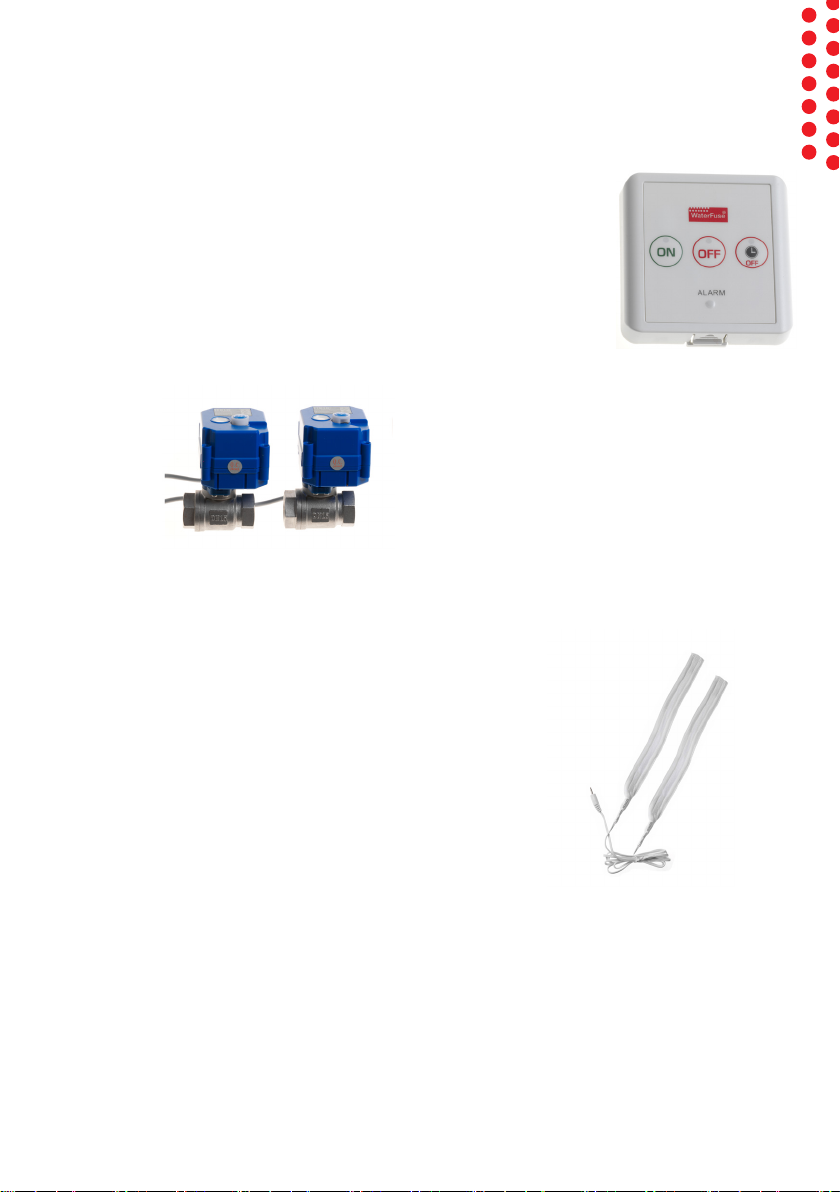
Components
– Central unit, art. no. 2220092
– Motorised ball valve, art. no. 2130051- DN15
– Water sensor, art. no. 2230011
– DC adapter, Manual
The motorised ball valve can be ordered G15 (DN15), G20 (DN20).
(Up to three parallel motorised ball valves can be installed. Additional valves
can be ordered separately)
5(12)
1.2 The Different Parts:
The central unit:
The central unit controls the motorized ball valves and looks for for
leaks with the help of the water sensors.
Mount in a suitable place in, for example, the sink cabinet.
Motorised Ball Valves:
Motor ball valves to turn the water the ON
and OFF of the water are installed near the
area/equipment which is to be monitored.
They can also be operated manually with a
mechanical knob on the unit if the power goes
out. Lift the knob 5 mm and turn clockwise to
close the valve. The indicator next to the knob shows open/closed.
Fitted on the cold and hot water pipes.
Water sensors:
The water sensors are placed on the obligatory
waterproof surface. If they indicate presence of water, the
central unit shuts the motorised ball valves and the leak is
stopped. Two water sensors are included but can be more
can be added.
Attach with the included Velcro tape on the waterproof
surface underneath the dishwasher and sink cabinet
which are to be monitored.

6(12)
1.3 Daily Operation:
The system constantly monitors for water leaks as an active protection against
water damage. No daily measures need to be taken.
You can also manually turn the water on/off as below.
Turn the water on
• Press ON. Green light indicates that the water is on.
• The water stays on permanently or according to the set timer.
The timer for the water being on is set using the DIL switches, see
section 2.3. (Factory setting permanently) Repeatedly pressing ON
reloads the timer with the set time.
Turn the water off
• Press OFF. Red light indicates that the water is off.
Delayed shutoff of the water
• Press DELAYED OFF. Red light indicates that the water will turn off
after a while.
• The time until the water is switched off is set with the DIL switches,
see section 2.3. (Factory setting 2h) Repeatedly pressing DELAYED OFF
reloads the timer with the set time.
1.4 Alarm:
The water sensor indicates water
• Water indication from a water sensor. The ball valve closes automatically
and the central unit goes to the OFF position. The ALARM LED flashes,
and the buzzer pulsates.
• Fix the error. If necessary, contact the installer.
• Confirm the alarm by pressing OFF.
1.5 External Control:
With the help of external control, an alarm or property control can control
the water ON/OFF. Note that the last keystroke or control signal overrides the
previous ones. Connect according to the description in section 2.4.

7(12)
2 Assembly Instrucons
2.1 General:
The product must be installed by a person who has the professional knowledge required
to perform the installation correctly. Unless the installation is performed by a professional,
the insurance companies may claim that the insurance does not cover any damage that
has occurred and that the offers made by the insurance companies to the property owner
are invalid.
If the ball valves are open for more than 72 hours, the ball valve is exercised automatically,
but the water is not completely turned off.
With a water switch, a washing machine can also be placed in the kitchen without a
floor drain, if there is a waterproof surface and a water sensor is placed so that any
water leaking from the equipment can be detected so that the leak can be automatically
stopped. (According to Safe Water Installation 2016: 1 Section 3.6.3)
This of course also applies to other pressurised equipment such as dishwashers, coffee
machines, and refrigerators / freezers with automatic water supply. If a water-connected
appliance other than a dishwasher or washing machine is connected, the installation must
be supplemented with a non-return valve, according to Safe Water Installation 2016:1
Section 4.3.4.
2.2 Installation:
Motorised Ball Valves: (art. no. 2130051)
The unit is intended for tap water, 0-60 ° C and 0-10 bar.
Fitted on the cold and hot water pipes. They can be mounted
horizontally, vertically, or upside down and independent of
flow direction. The unit has an internal R-thread. Connect to
them to pipes, for example with compression fitting according to the pipe and coupling
manufacturer's instructions. Use the required sealant. The unit must not be mounted in a
concealed place; it must be placed so that it can be changed and so that any leaking water
can be easily detected. The units must be installed in a room with a waterproof floor, in a
distribution cabinet, or in a custom space. If a distribution cabinet is used, the installation
instructions for this must be followed.
After mounting, the installation must be checked for leaks with the tap water installation's
existing water pressure according to the instructions on www.säkervatten.se.
(Up to three parallel motorised ball valves can be installed. Additional valves are ordered
separately)
8(12)
Central unit: (art. no. 2220092)
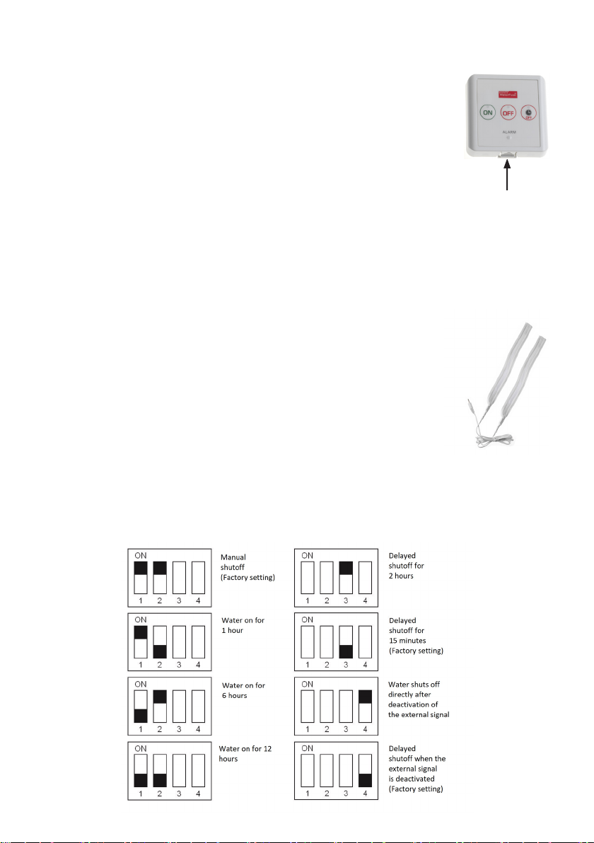
The sink cabinet is a suitable place for installation. The box has a "button" on
the underside that is used to open it.
The cable from the ball valves is pulled to the central unit and connected to the 2-pole
terminal V3 with red cable to +. (For more valves, both V1 and V2 are used.)
The water sensor has a socket that is connected directly to the outside. The supplied
DC adapter must be used for power supply or if the property has 12 vdc, it is connected
via a terminal block on the circuit board. All cables can be connected on the back of
the central unit to avoid visible wiring, disconnect the centre plate on the mounting
plate and connect the cables to the terminals. Alternatively, use the premade hole at
the bottom of the casing. See section 2.5.
Water sensors: (art. no. 2230011)
The included water sensor is placed under the appliance which is to be
monitored and is easily connected to the socket directly in the central unit
or via a terminal directly on the circuit board. Use the supplied Velcro tape
to mount the water sensor.
2.3 Settings:
There are a number of settings that can be changed for the product.
Settings are changed with dip switches on the central unit circuit board. Changes to the
dip switches are easily made by using a pen or a small screwdriver to move the switch.
The black marking below shows the plastic switch you are moving. The plastic switch
can be black, white, or blue.
"Button"

9(12)
2.4 Connection to Alarm or Other Remote Controls
WaterFuse® Kitchen can be connected to a master alarm or property control
system and thus becomes part of that system. This allows you to turn the
water to the equipment on and off automatically.
The input port uses optocouplers to protect the electronics.
Suggestion for connection to external controls:
• Jumper + Out with + Ext. Install switch between –Ext and 0v.
• When the switch is closed, the optocoupler / signal is activated and the
water is turned on.
• When the switch is opened, the optocoupler / signal is deactivated and
the water is turned off immediately or with a delay according to DIL
switch 4.
2.5 Connecting the Cables:
Terminal block - K82
Ball valve 1 is connected to V3. Red on +.
Terminal block - K80
Ball valve 1 is connected to V1. Red on +. (If connecting via the back cover)
Ball valve 2 is connected to V2. Red on +. (If extra ball valve is fitted)
The terminal outputs for V1 and V2 are parallel to V3 on K82.
Extreme voltage supply 12vdc between +12/24 and 0v
Terminal block - K81
Water sensor between Prb and Prb.
External control of on / off with + Out, 0v,
+ Ext, -Ext.
+ Out = + 12vdc
0v = GND (0v)
+ Ext, -Ext = Connection to optocoupler
(alarm input)

10(12)
2.6 Water-Connected Appliances
According to Safe Water Installation 2016: 1, the following conditions must be
met even if a water switch is installed:
• The water connection to the washing machine must have a shut-off valve
with a control device that is visibly located and easily accessible. [Section
3.6.3]
• The water connection to the dishwasher must have a shut-off valve
with a control device that is visibly located above the counter and easily
accessible. [Section 3.7]
• Other water-connected appliances, e.g. ice machine or coffee maker, must
have a shut-off valve with an easily accessible control device [Section 3.7]
and be supplemented with non-return valve. [Section 4.3.4]
3 Technical Specicaons
ELECTRICITY PHS
230 vac för 12v dc-adapter G20(DN20) alt. G15(DN15)
Motorised ball valve with
manual override
Up to three parallel motorised
ball valves may be installed.

11(12)
4 Warranty and Limitaon of Liability
In addition to the terms of the Consumer Purchase Act, a 1-year functional warranty is
provided for the product.
The warranty stipulates that during normal use and maintenance, the product must be
free from defects in design and function. The warranty period is calculated from the date
of purchase, which must be proven by a receipt from the place of purchase. The warranty
presupposes that the product has been installed appropriately and in accordance with
the written instructions. The plumbing installation must be completed by a plumber.
If you have questions or problems with your product, you should first contact the dealer
who sold or installed your equipment. Before you report a fault /complaint about your
broken product, please read the operating instructions and, if possible, check that all
settings are correct. The warranty stipulates that defective parts or components will
be replaced with defect-free ditto. The customer is responsible for all overhead, unless
the Consumer Sales Act is applicable. This means that shipping costs, inspection, and
assembly costs are not included in the warranty commitment.
If possible, use the original packaging if the product needs to be transported.
The transport companies do not compensate for damage if the product has been poorly
packaged.
The warranty does not apply to defects that occur during or after making your own
changes to the product's function or appearance, such as rebuilding, upgrading, or other
configurations of the product made without written approval.
The warranty does not cover faults that have arisen through an accident or malicious
damage.
The warranty does not cover deterioration that has occurred after the purchase, if
the seller can prove it probable that the deterioration is due to neglected or incorrect
maintenance or that the appliance has been used for something other than its intended
purpose, that inappropriate measures, unauthorised or incorrect interventions have been
made or that installation instructions were not followed.
Batteries are considered consumables and are not covered by the warranty.
The reseller is not responsible for loss or damage of any kind caused by this
product. The liability is, in any case, strictly limited to the replacement of the product.

12(12)
Tel:018-349010
info@tollco.se
www.tollco.se
Tollco AB
Rubanksgatan 4
741 71 Knivsta
Table of contents


